* Corresponding author.
E-mail addresses: jordanmaximov@gmail.com (J. T. Maximov)
© 2014 Growing Science Ltd. All rights reserved.
doi: 10.5267/j.esm.2014.7.001
Engineering Solid Mechanics 2 (2014) 247-264
Contents lists available at GrowingScience
Engineering Solid Mechanics
homepage: www.GrowingScience.com/esm
Enhancement of fatigue life of rail-end-bolt holes by slide diamond burnishing
J. T. Maximov*, G. V. Duncheva, A. P. Anchev, I. M. Amudjev and V. T. Kuzmanov
Department of Mechanical Engineering, Technical University of Gabrovo, 5300 Gabrovo, Bulgaria
A R T I C L E I N F O A B S T R A C T
Article history:
Received June 6, 2014
Accepted 17 June 2014
Available online
19 July 2014
The fatigue failure around rail-end-bolt holes is particularly dangerous since it leads to
derailment of trains and consequently to inevitable accidents. It is well-known that the fatigue
life of structural holed components, subjected to cyclic load, can be increased by generating
compressive hoop stresses around the holes. These beneficial residual compressive stresses
significantly reduce the maximum values of the operating tensile stresses arising at the critical
points of the components and thus impede the formation of first mode cracks. A new approach
to enhancement of fatigue life of rail-end-bolt holes has been developed. The approach involves
sequential drilling and reaming through a new combined tool and then slide diamond
burnishing by a new device. The technology implementation was carried out on machine tool.
The process of creating residual stresses has been studied both experimentally and numerically.
The experimental study was conducted by means of a modified split ring method. A reliable
finite element modeling approach to the slide diamond burnishing process was developed. On
this basis, the process was optimized by means of a genetic algorithm. As a result, the optimal
combination of the governing process parameters is established, which ensures both maximum
depth of the compressive zone and maximum absolute values of the residual stresses.
© 2014 Growin
g
Science Ltd. All ri
g
hts reserved.
Keywords:
Rail-end-bolt holes
Fatigue failure
Residual stresses
Cold working
Finite element simulation
1. Introduction
Railway transport is acquiring greater significance in the development of modern transport. This
tendency is a direct consequence from the energy and environmental crises. In this aspect research
directed to higher safety, long life and economy of components composing railways, is becoming
more and more topical.
Building of high-speed railway lines is related to the so-called continuously welded rails.
However, bolted joint railways cannot be done away with by 100% – in broken country and
curvilinear railroad tracks they have no alternative. There are a large number of bolted rail joints in
heavy lines and mountainous lines. In Bulgaria, for instance, bolted joint railroads are 64.4% of the
2
r
j
r
d
(
t
c
m
T
t
o
c
s
i
b
b
c
a
A
I
c
e
(
a
a
i
w
s
l
h
r
o
2
48
r
ailway net
w
oint bars
o
r
emaining
c
d
epend on
t
(
Fig. 1). Th
t
rains (Cai
c
omponent
s
m
ostly aro
u
T
orabi and
A
t
he bolt hol
e
Fi
g
.
1
The fati
g
o
f trains a
n
c
ontinue w
h
s
afety of t
h
i
mportance
b
olted joint
It is wel
l
b
e increase
d
c
ompressiv
e
a
t the critic
a
A
commo
n
I
mplementi
n
c
old expan
s
e
nhanceme
n
(
Maximov
e
a
bove two
m
When th
a
pproach is
i
s to achie
v
w
hile the a
c
s
lide diamo
n
l
ow-cost de
v
h
ole surfac
e
r
esistance.
A
o
f 100000
m
fishpl
a
w
ork and t
h
o
r fishplate
s
c
onditions
a
t
he state o
f
e elements
et al., 20
0
s
or railwa
y
u
nd the bo
l
A
liha, 201
3
e
s in the en
d
1
. Bolted r
a
g
ue failure
a
n
d consequ
e
h
en defect
s
h
is sort of
to the saf
e
railroads.
l
-known th
a
d
by gener
a
e
stresses s
i
a
l points of
n
approac
h
n
g this app
s
ion metho
d
n
t of fatig
u
e
t al., 2013
m
ethods re
q
e processi
n
appropriat
e
v
e the max
i
c
curacy of
s
n
d burnishi
v
ices; low
f
e
- accordi
n
A
ccording
t
m
.
a
te
bolt co
n
h
eir overall
s
and four
a
re the sam
e
f
compone
n
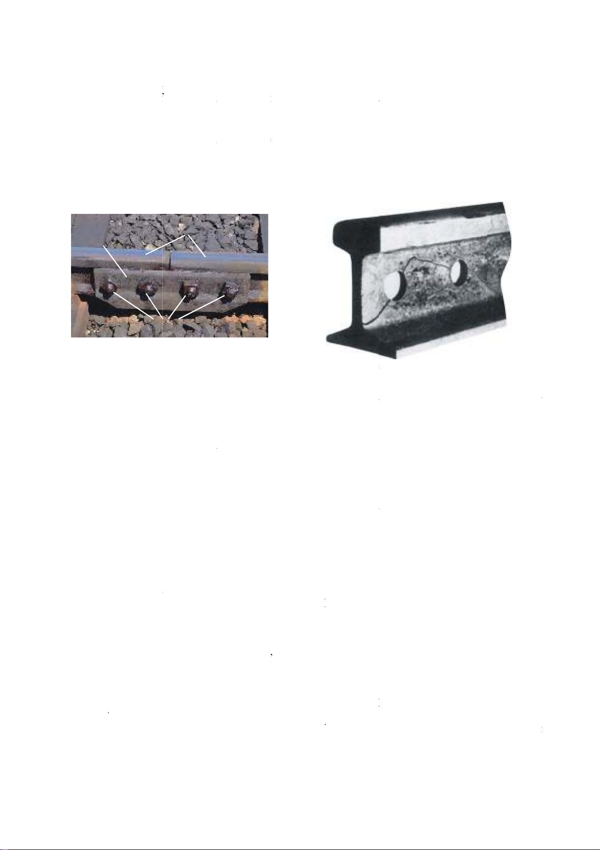
in a rail jo
i
0
7). The d
y
y
axles an
d
l
t holes or
3
). A mode
d
rail (Fig.
2
a
il joint co
m
a
round rail
-
e
ntly to in
e
s
appear in
transport.
e
ty of rail
w
a
t the fatig
u
a
ting comp
r
i
gnificantly
the compo
n
h
to impa
r
roach, the
F
d
and espe
c
u
e life of r
a
), is devel
o
q
uires speci
a
n
g of rail-
e
e
- taking a
d
i
mum dept
h
s
hape and s
i
ng. Other
a
f
riction coe
n
g to Korz
y
t
o Yatzenk
o
rails
n
nection
s
extended
l
bolts are
u
e
, reliabilit
y
n
ts composi
n
i
nt are subj
e
y
namic cha
r
d
respective
notches,
w
o
f failure i
n
2
).
m
ponents
-
end-
b
olt h
o
e
vitable ac
c
the rail h
e
Therefore,
w
ay transpo
r
u
e life of st
r
r
essive nor
m
reduce the
n
ents and t
h
r
t benefici
a
F
TI compa
n
c
ially adap
t
a
il-end-
b
olt
o
ped in (D
u
a
l equipme
n
e
n
d
-
b
olt h
o
d
vantage o
f
h
of the zo
n
i
ze are irre
l
a
dvantages
o
fficient bet
w
y
nski (2013
)
o
(1985) th
e
l
ength is 4
7
u
sed to co
n
y
, service li
f
ng rail joi
n
e
cted to cy
c
r
acter of l
o
e
ly provoke
w
hich are n
a
n
bolted joi
n
Fi
g
.
2
hole
o
les is parti
c
c
idents. A
n
e
ads, the b
r
the fatigu
e
r
t, service
l
r
uctural ho
l
m
al stresse
s
maximum
v
h
us impede
a
l residua
l
n
y has dev
e
t
ed to rail-
e
holes, bas
e
u
ncheva &
M
n
t.
o
les is per
f
f
the
b
urnis
h
n
e of resid
u
l
evant. Tho
s
o
f this met
h
w
een the d
e
)
this coef
fi
e
deformin
g
7
60 km (V
a
n
nect the e
f
e as well a
s
n
ts: rail en
d
c
lic and im
p
o
ads cause
s
s originati
n
a
tural stres
s
n
ts is fatig
u
2
. Typical
c
c
ularly dan
g
n
d whereas
r
eaking of
e
failure a
r
l
ife and m
a
l
ed compo
n
s
around t
h
v
alues of t
h
t
he formati
o
l
stresses
e
loped Rai
l
e
n
d
-
b
olt h
o
e
d on the s
M
aximov,
2
f
ormed on
h
ing techno
u
al compre
s
e require
m
h
od are: eas
y
e
forming el
fi
cient is in
g
element
d
a
lkov and
G
n
ds of adj
o
s
maintena
n
d
s, joint ba
r
p
act loads
a
s
fatigue i
n
n
g and gro
w
s
concentr
a
e crack init
c
racks origi
n
g
erous sinc
the exploi
t
rail ends
d
r
ound bolt
e
a
intenance
a
n
ents, subje
c
h
e holes. T
h
h
e operatin
g
o
n of first
m
around a
l
Tec syste
m
les (Reid,
1
y
mmetric
c
2
013). The
machine
t
l
ogies. The
s
sive stres
s
m
ents can b
e
y
impleme
n
e
ment (arti
f
the range
0
u
rability re
G
rozdanov,
o
ining rail
s
n
ce and rep
a
r
s and bolt
a
s a result
o
n
material
i
w
th of fati
g
a
tions(Cai
e
t
iation and
g
n
ating at ra
i
c
e it leads t
o
tation of r
a
d
irectly jeo
p
e
d holes is
a
nd repair
c
ted to cyc
l
h
ese benefi
c
g
tensile str
e
m
ode crack
s
hole is c
m
, based on
1993). An
c
old expan
s
implemen
t
t
ools (Fig.
main requ
i
s
and a lo
w
e
satisfied e
n
tation wit
h
f
icial diam
o
0
.02 to 0.0
8
e
aches proc
e
2009). Tw
o
s
. When th
e
a
ir activitie
s
connection
s
o
f passing o
i
n rail joi
n
g
ue cracks
e
t al., 200
7
g
rowth fro
m
i
l-end-bolt
o
derailme
n
a
ilroads ca
n
p
ardizes th
e
of limitin
g
activities o
l
ic load, ca
n
c
ial residu
a
e
sses arisin
g
s
.
o
ldworkin
g
split sleev
e
approach t
o
s
ion metho
d
t
ation of th
e
3), anothe
i
rement her
e
w
roughnes
s
n
tirely fro
m
h
a relativel
y
o
nd) and th
e
8
; high wea
r
e
ssed lengt
h
o
e
s
s
f
n
t
-
7
,
m
n
t
n
e
g
f
n
a
l
g
g
.
e
o
d
e
r
e
s
,
m
y
e
r
h

J. T. Maximov et al. / Engineering Solid Mechanics 2 (2014)
249
Fig. 3. Processing of rail-end-bolt holes on machine tool in FAE Sofia
To assess the effect of applying the slide diamond burnishing, it is necessary to know in
quantitative and qualitative aspect the residual stress distribution around the rail-end-bolt holes. Since
the fatigue failure at the rail ends is caused by originating and growth of first mode cracks around the
bolt holes, the residual hoop normal stresses are crucial.
Unfortunately, in Bulgaria, as well as in many other countries, the problem of fatigue failure of rail-
end-bolt holes is underestimated and consequently the appropriate treatment of these holes is also
underestimated.
The main objective of the study is to find the distribution of beneficial residual normal hoop
stresses around rail-end-bolt holes after slide diamond burnishing. To reach the target both
experimental and numerical approaches are used.
2. Experimental part
2.1. Rail-end-bolt holes treatment experiment
In the present study, disc-shaped samples with diameter of mm100 and thickness of mm17 were
used. The work material was steel 76 (equivalent to rail steel R260) with chemical composition
shown in Table 1. STAMA vertical machining center was used for both drilling-reaming and
diamond burnishing. The experiment was conducted at Impuls JCS - Gabrovo. Special tools (Fig. 4)
were designed by the authors and manufactured by “Ceraticit Bulgaria” JCS – Gabrovo.
Table 1. Chemical composition of steel 76 in percentages
C Si Mn P S Cr Mo Ni Al Cu Ta Fe
0.75 0.213 0.74 0.022 0.041 0.029 0.015 0.055 0.018 0.03 0.015 98.045
The first four specimens were subjected to drilling and reaming using our combined tool. The
manufacturing parameters feed rate and speed were changed in two levels (see Table 2). These
parameters were recommended by the manufacturer of carbide inserts.
Table 2. Manufacturing parameters and results
Specimen № Speed, rpm Feed rate, mm/rev Diameter size, mm Roughness, Ra
1 1000 0.15 33.38/33.38 1.50
2 1400 0.15 33.39/33.38 1.56
3 1000 0.2 33.38/33.37 2.19
4 1400 0.2 33.38/33.38 2.21
5 1000 0.15 33.39/33.39 0.39
6 1400 0.15 33.40/33.39 0.27
7 1000 0.2 33.39/33.39 0.27
8 1400 0.2 33.40/33.39 0.38

250
The following four specimens were successively subjected to drilling and next reaming through
our combined tool, and next diamond burnishing with the same manufacturing parameters. The
burnishing tool was constructed for bilateral processing. The radius of the spherical diamond tip was
mmr 1. Burnishing force of N400 was applied.
The obtained holes roughness has been measured using a Mitutoyo surftest-4 instrument. Each
experimental value of the roughness has been obtained in the following way: the measurement was
taken on three generatrixes situated at 0
120 as for each generatrix the mean value of the roughness
has been given. The final value of the roughness has been found as an arithmetic mean of the
obtained roughness for the three generatrixes. To evaluate the shape deviation, the diameters of the
processed holes have been measured in the two sections.
On the basis of the results obtained (Table 2) the following comments can be made with respect to
the influence of the process manufacturing parameters:
▪ In the previous processing (by cutting), the roughness depends on the process parameters: by
increasing the feed rate, it deteriorates; by increasing the speed, the roughness weakly deteriorates
▪ Despite the different initial conditions, after diamond burnishing, the obtained roughness is
practically constant, and the reduction in the average roughness compared to the previous treatment is
about 6 times.
Fig. 4. New tool setup: a. drill-reamer; b. slide diamond burnishing tool
2.2. Residual stress determination
2.2.1. Nature of the employed method
It is well-known (Fattouh and El-Khabeery, 1989) that the generated zone with beneficial residual
stresses after burnishing covers only the surface layers. One of the most used experimental methods
for measurement of residual stresses is the x-ray diffraction (Webster and Ezeilo, 2001). This method
is frequently used in cases of cold expanded holes (Maximov et al., 2009; 2012; 2014). However, to
measure the residual hoop stresses around diamond burnished holes, the x-ray diffraction method is
inapplicable for two main reasons:
• the diameter of the x-ray beam is commensurate with the depth of the compressive zone, and
therefore, the residual stresses can not be measured in the available front surfaces;

J. T. Maximov et al. / Engineering Solid Mechanics 2 (2014)
251
• the x-ray beam can not be directed tangentially to the hole surface.
Of the other experimental methods, the stress relief approach is suitable for this case. An object of
measurement are the residual circumferential normal stresses res
t
(stresses of first type) which have a
decisive role for the fatigue life of rail-end-bolt holes. The stress relief approach has been used. The
latter is based upon the following assumption that the removal of a part of the specimen is equivalent
to applying a distributed load to its remaining part and the load intensity is equal to the magnitude of
residual stresses but has an opposite sign. This load causes deformation whose magnitude is used for
calculating res
t
.
Three basic methods implement this idea. Chronologically, the first known method belongs to Zaks
(1924). He developed a method for determination of residual stresses in thin-walled tubes. The
method requires considerable accuracy of measurement of the linear changes since the deformations
of the pipes are very small when thin layers are removed from the samples. Significantly more
effective is the method developed by Davidenkov (1931), in which the tube is pre-cut along to one
generatix. Thus, the obtained bending deformations are much higher in comparison with those of the
Zaks’ method. Deflection etching technique is based on removal of thin layers of stressed material
from the machined surface region by electrochemical action (Sadat, 2012). This method was first
developed by Frisch and Tompsen (1951) and later was used by many researchers (Sadat and Bailey,
1985; Fattouh and El-Khabeery, 1989; El-Khabeery and Fattouh, 1989; El-Axir, 2000, 2002;
Belgasim and El-Axir 2010).
Over the years many modifications of the three methods have been developed. On the physical
basis of the Davidenkov’s method, Birger (1963) modified Davidenkov’s "split ring" method, and
Vitman (1935) developed a simplified methodology. These methods are now widely used in Russia.
In the present study a modification of the “split ring” method has been applied (Fig. 5). Removing
layers is performed chemically, and the calculation of residual stresses is made for the lines of the
centers of gravity of the removed layers through an incremental way.
Fig. 5. A scheme of the split ring method
The hoop stress *
i,t
in the i-th layer, immediately before removal is:
)3(
i,t
)2(
i,t
)1(
i,t
res
i,t
*
i,t
, (1)
where:
mm4.33d
0
mm2L
i
L
i
d
i
r
i
h
res
i,t
res
i,t
i-th layer
b=5 mm
D=43 mm
i
h

![Bài tập tối ưu trong gia công cắt gọt [kèm lời giải chi tiết]](https://cdn.tailieu.vn/images/document/thumbnail/2025/20251129/dinhd8055/135x160/26351764558606.jpg)