A NOVEL CONTROL STRATEGY TO ENHANCE THE DYNAMIC
RESPONSE OF THE WIND ENERGY CONVERSION SYSTEM
USING A DOUBLY FED INDUCTION GENERATOR BASED ON AN
INTELLIGENT FUZZY-PI CONTROLLER
Nguyen Thi Hue
1
, Huynh Hoang Bao Nghia
2
, Le Van Dai
2*
1
Dong Nai Technology University
2
Industrial University of Ho Chi Minh City
*Corresponding author: Le Van Dai, levandai@iuh.edu.vn
1. INTRODUCTION
The increasing global demand for electrical
energy has intensified its influence on
geopolitical issues, including economic and
environmental concerns. Renewable energy
sources such as wind, solar, and hydroelectric
power are becoming critical solutions to meet
current and future electricity demands
worldwide (Le Dai, Pham, 2023). Among
these, wind energy contributes approximately
24% to the global renewable energy mix as of
2023, making it one of the most promising
sources of electricity generation (LV Dai,
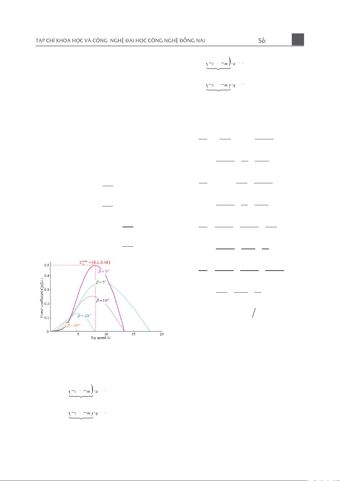
Tung, 2017; Hassan et al., 2024). Wind turbines
(WTs), as a crucial component of wind energy
conversion systems, are responsible for
converting kinetic energy from wind into
electrical energy, with modern turbine
efficiencies reaching up to 50%. Over the years,
advancements in wind turbine technologies
have led to the development of three primary
operational types: fixed-speed, semi-variable
speed, and variable-speed turbines, with
variable-speed systems achieving up to 30%
GENERAL INFORMATION ABSTRACT
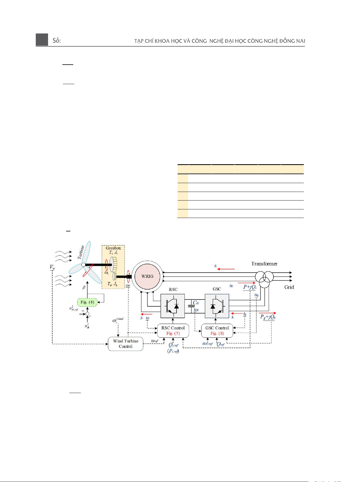
Received date: 10/11/2024 This paper introduces a practical and simple power control
method for wind energy conversion systems based on a
doubly-fed induction generator. Due to the limitations of
traditional proportional-integral controllers when the
parameters of the doubly-fed induction generator and wind
speed vary, fuzzy control theory is applied to overcome these
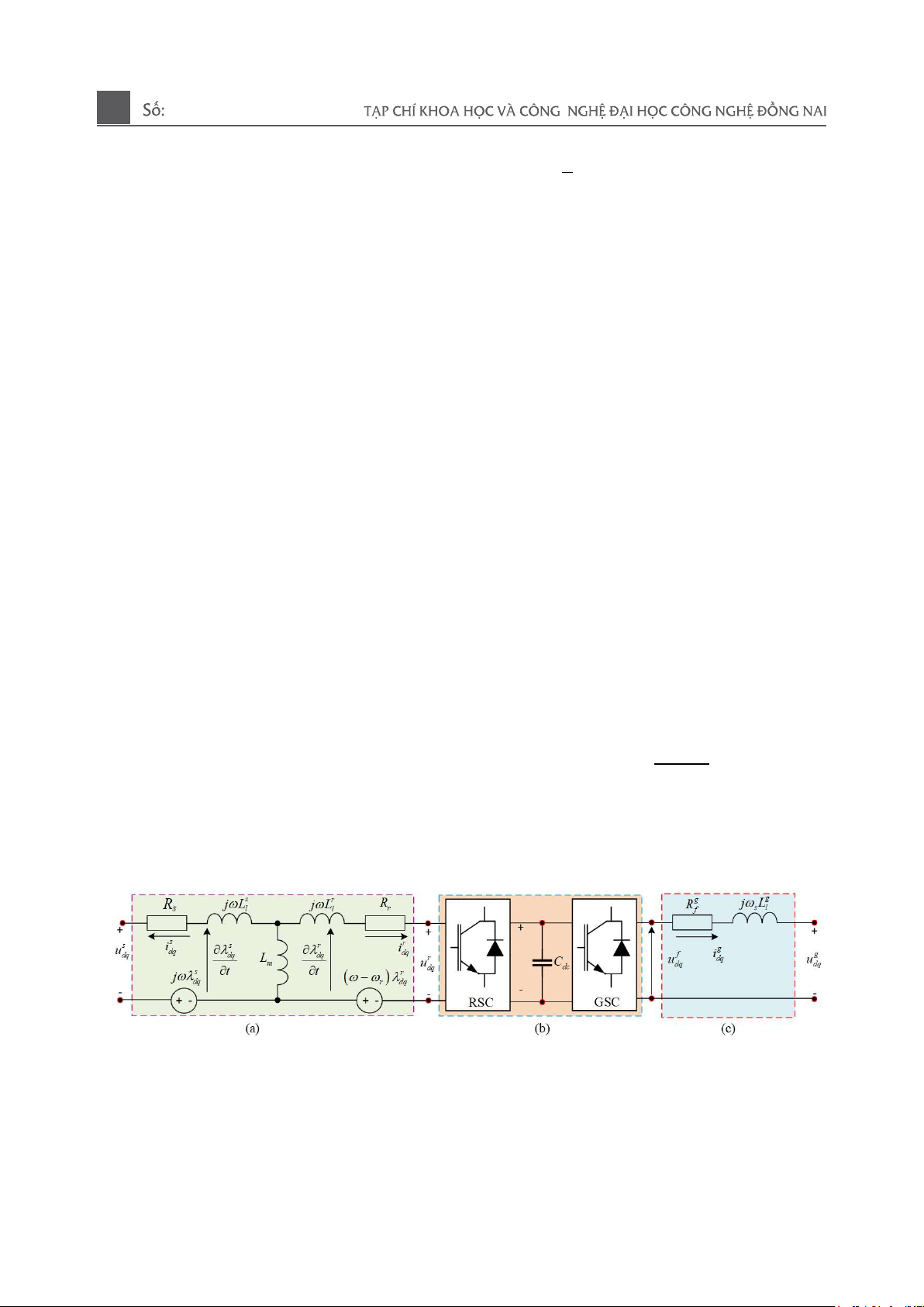
challenges. First, a detailed mathematical model of the
induction generator in the dq domain is provided. Then, based
on the characteristics of the doubly-fed induction generator, an
enhanced mathematical model is presented along with a vector
control model for the generator. Subsequently, the
mathematical model for the wind turbine and the fuzzy
controller based on the proportional-integral controller are
developed and implemented in MATLAB/Simulink for
simulation and performance evaluation. Simulation results
indicate that the proposed method for controlling the doubly-
fed induction generator can significantly improve the dynamic
response performance under varying generator parameters and
wind speed conditions.
Revised date: 03/01/2025
Accepted date: 08/01/2025
KEYWORD
Doubly fed induction generator
(DFIG);
Dynamic response;
Fuzzy control;
Wind energy conversion system
(WECS);
Proportional-integral (PI);
Simulation analysis
.
01-2025
10
higher energy capture (Ackermann, 2012). One
of the most widely used turbine-generator
systems is based on doubly-Fed induction
generators (DFIG), which are controlled by
back-to-back power converters accounting for
approximately 50% of installed wind farms
globally, covering both onshore and offshore
applications (Liserre, Cardenas, Molinas, &
Rodriguez, 2011). DFIG-based wind energy
conversion systems (DFIG-WECS) have
gained significant attention due to their
capability to handle wind speed variations
between 4 m/s to 25 m/s efficiently and to
control active and reactive power
independently, maintaining a power factor
close to unity (Mehdipour, Hajizadeh, &
Mehdipour, 2016). Research on DFIG-WECS
models has primarily focused on addressing
wind speed variability, improving power
quality, and enhancing system dynamics
(Bensahila, et al., 2020; Boutoubat et al., 2013;
Mehdipour et al., 2016). Several control
techniques have been proposed to enhance the
performance of wind energy systems: The
study by (Abolhassani, et al., 2008) developed
a WECS model to maximize wind power
capture and improve power quality by reducing
nonlinear harmonic currents by up to 90%.
However, this model did not address reactive
power compensation or overload in the rotor
side converter (RSC), which is critical for grid
integration. Research (Singh, Chandra,
2010) introduced a grid side converter (GSC)
model that acted as an active filter, achieving
harmonic compensation within 5% of IEC
standards while maintaining a power factor
above 0.98. Research (Jain, Ranganathan,
2008) proposed using the GSC in parallel
operation for independent power grids,
achieving voltage regulation within ± 5% under
varying load conditions. The above approaches
provide promising control theories, but there
are still challenges in optimizing the control
systems to improve reliability, scalability, and
stability under different operating conditions.
To address these gaps, this paper proposes a
mathematical model of DFIG-WECS to study
the ability to regulate the stator and rotor
currents, ensuring stable output power under
different wind conditions. The model
demonstrates that the system can maintain
output stability at wind speeds ranging from 6
m/s to 20 m/s, with power fluctuations limited
to ± 3%. The rest of this paper is structured as
follows: Section 2 discusses the theoretical
framework of the WT generator model. Section
3 details the control system for DFIG-WECS.
Section 4 presents the studies under different
wind speed scenarios, followed by conclusions
presented in Section 5.
2. WECS MODEL
The block diagram of the overall control
system for the DFIG-WECS is illustrated in
Fig. 1. It consists of two main parts: The first
part is the electrical control system of the DFIG,
which includes the RSC and the GSC. The
objective of the RSC is to enable the DFIG WT
to control active and reactive power or speed
independently. Meanwhile, the GSC aims to
maintain the DC link voltage at a specified
value, regardless of the direction and magnitude
of the rotor power. The second part is the
mechanical control system of the WT, which
primarily aims to achieve maximum wind
power extraction and minimize low-speed load
stresses. Therefore, controlling the DFIG-
WECS system is essential and will be presented
in the following subsection.
2.1. Wind Turbine
The presentation of the mechanical system
of an entire WT is quite complex. For modeling
and simulation, a two-mass drive model is
proposed to study the dynamic stability of the
electromechanical system, which is expressed
by the following equations (LV Dai, Tung,
2017)
01-2025
11
t
t t
g
g g g g
g
t
J T T
t
J T T D
t
=
=
(1)
where; J
t
is the turbine inertia constant, T
t
is the turbine torque, T
g
is the generator torque,
ω
t
is the turbine speed, J
g
is the generator inertia
constant,
ω
g
is the generator speed, D
g
is the
friction coefficient of the generator and P
m
is
the wind turbine mechanical power and is given
as (Miller et al., 2003; Tohidi et al., 2016):
(
)
m w ,
p
P P C
=
(2)
The wind power swept can be converted
depending on the air density ρ, β is the tip speed
ratio, λ is the blade pitch angle, the turbine
blade radius R, and the wind speed V
w
, as (Yang
et al., 2017):
2 3
w w
1
2
P R V

=
(3)
The power coefficient can be defined as:
( )
4 4
,
0 0
,
i j
p i j
i j
C
= =
=
(4)
where α
i,j
is the coefficient given in Table
1, The curve fit is a good approximation for
values of 2 < λ < 13. Values of λ outside this
range represent very high and low wind speeds,
respectively, that are outside the continuous
rating of the machine (LV Dai, Tung, 2017;
Miller et al., 2003).
Table 1: The coefficient of α
i,j
for i, j = 0, … ,4.
i/j 0 1 2 3 4
0 -4.1909e-1 2.1808e-1 -1.2406e-2 -1.3365e-4 1.1524e-5
1 -6.7606e-2 6.0405e-2 -1.3934e-2 1.0683e-3 -2.3895e-5
2 1.5727e-2 -1.0996e-2 2.1495e-4 -1.4855e-4 2.7937e-6
3 -8.6018e-4 5.7051e-4 -1.0479e-4 5.9924e-6 -8.9194e-8
4 1.4787e-5 -9.4839e-6 1.6167e-6 -7.1535e-8 4.9686e-10
Figure 1. Block diagram of WECS
The turbine tip-speed ratio λ
opt
is defined as:
t
w
opt
opt
R
V
=
(5)
Fig. 2 illustrates the variation of the power
coefficient C
p
concerning the tip speed
ratio λ at different pitch angles. Observing this
figure, the pitch angle is controlled at low to
medium wind speeds to allow the WT to
operate under optimal conditions. At high wind
speeds, the pitch angle is adjusted to release
some aerodynamic energy. WT are typically
designed to harness the maximum possible
wind energy at wind speeds ranging from 10 to
01-2025
12
15 m/s. When wind speeds exceed 15 m/s, the
turbine may shed some energy and will
completely shut down at wind speeds reaching
20 to 25 m/s.
2.2. WRIG
The equivalent circuit of the DFIG-WECS
is shown in Fig. 3-(a). For this study, the
generator selected is the DFIG. Its
mathematical expressions are formulated in the
dq-axis reference frame of the synchronous
rotating system and can be represented as (LV
Dai & Tung, 2017; Jazaeri, Samadi, Najafi, &
Noroozi-Varcheshme, 2012):
s
s s s d
d s d q
s
q
s s s
q s q d
u R i t
u R i t


= +
= + +
(6)
( )
( )
r
q
r r r
d r q r d
r
r r r d
q r d r q
u R i t
u R i t
= + +
= +
(7)
Figure 2. Power coefficient curves versus tip
speed ratio for various pitch angles
Next, equations of magnetic flux of the
rotor and stator:
(
)
( )
s
s
s s s r
d l m d m d
L
s s s r
q l m q m q
L
L L i L i
L L i L i
= + +
= + +
(8)
(
)
( )
r
r
r r r s
d l m d m d
L
r r r s
q l m q m q
L
L L i L i
L L i L i
= + +
= + +
(9)
According to Eqs. (6), (7), (8), and (9),
the current equation can be rewritten under the
following form:
s s r
s
d s d r m d
r q
s s r
rs r
r m q d m d
s s s r
s s r
q s q
sr m d
r d
s s
r s r
r m q q m q
s r s s r
i R i R L i
i
t L L L
L i u L u
L L L L
i R i L i
i
t L L
R L i u L u
L L L L L
= + +
+ +
=
+ +
(10)
2
2
s
r s r
r m q
d s m d r d
s r r s
rs r
r m q m d d
s r s r r
r s r
s
q s m q r m q
r m d
s s r s r
r s r
r q m q q
r s r r
L i
i R L i R i
t L L L L
L i L u u
L L L L L
i R L i L i
L i
t L L L L L
R i L u u
L L L L
=
+
= + +
+
(11)
where
)
2
s r m s r
L L L L L
=
,
r m
p
=
,
s
d
u
is
the d-axis stator voltage,
s
q
u
is the q-axis
stator voltage,
r
d
u
is the d-axis rotor voltage,
r
q
u
is the q-axis rotor voltage,
s
d
i
is
the d-axis stator
current,
s
q
i
is the q-axis stator current,
r
d
i
is the
d-axis rotor current,
r
q
i
is the q-axis rotor
current,
s
R
is the stator resistance,
r
R
is the
rotor resistance,
s
d
is
the d-axis stator flux,
s
q
is the q-axis stator flux,
r
d
is
the d-axis rotor
flux,
r
q
is the q-axis rotor flux,
is the angular
speed of the synchronously rotating reference
01-2025
13
frame,
r
is the rotor angular speed,
s
L
is the
stator inductance,
r
L
is the rotor inductance,
s
l
L
is the stator leakage inductance,
r
l
L
is the rotor
leakage inductance,
m
L
is the mutual
inductance, and p is the number of pole pairs.
Next, the active and reactive power outputs
from the stator and rotor sides of the DFIG can
be derived from Eqs. (6), (7), (8), and (9) and
can be represented as follows:
(
)
( )
s s s s
s d d q q
s s s s
s q d d q
P u i u i
Q u i u i
= +
=
(12)
(
)
( )
r r r r
r d d q q
r r r r
r q d d q
P u i u i
Q u i u i
= +
= +
Next, the total active and reactive power
is:
total s r
total s r
P P P
Q Q Q
= +
= +
(13)
Next, by ignoring rotor and copper losses,
the active power of the rotor can also be
represented by the following equation:
s r
P sP=
(14)
Finally, the equation of electromagnetic
torque can be obtained as follows:
( )
1
2
s d s r
g m q r d q
T pL i i i i=
(15)
In this paper, when R
s
, R
r
,
r
l
L
and
s
l
L
and
the alternating current (AC) components related
to the type of impedance and reactance are
ignored. This leads to the model not accurately
reflecting the complex details. The stator
resistance R
s
and rotor R
r
cause energy loss. The
rotor
r
l
L
and stator
s
l
L
leakage currents cause the
dynamic consequences of the current. When
ignoring these parameters, from the formula (6)
and (7) we rewrite as:
s s
d q
s s
q d
u
u


=
=
(16)
(
)
( )
r r
d r d
r r
q r q
u
u
=
=
(17)
When the components R
s
, R
r
,
r
l
L
and
s
l
L
,
are ignored, the electromagnetic torque T
e
is
calculated incorrectly, resulting in the actual
mechanical speed ω
mech
not fully reaching the
optimum value
opt
t
. This deviation can be
described by:
s r
s r
l
op
t t
l
t
R R
L L
= +
+
(18)
in which, the deviation ratio depends on the
ratio between the resistance R
s
, R
r
and the total
reactance
r
l
L
,
s
l
L
.
Figure 3. Equivalent circuit of DFIG; (a) WRIG generator, (b) Power electronic converters and
DC link, (c) Grid filter
3. CONTROL STRATEGY
3.1. Wind Turbine Control
The pitch angle control adjusts the blade
pitch when wind speeds exceed the rated value,
limiting WT power output. As shown in Fig. 4,
01-2025
14