
* Corresponding author. Tel: +98 (21) 6616 5530; Fax: +98 (21) 6600 0021
E-mail addresses: afshin@sharif.edu (H. Afshin)
© 2017 Growing Science Ltd. All rights reserved.
doi: 10.5267/j.esm.2017.9.003
Engineering Solid Mechanics (2017) 225-244
Contents lists available at GrowingScience
Engineering Solid Mechanics
homepage: www.GrowingScience.com/esm
A parametric study on the effects of surface explosions on buried high pressure gas
pipelines
Omid Adibi, Amin Azadi, Bijan Farhanieh, Hossein Afshin*
Center of Excellence in Energy Conversion, School of Mechanical Engineering, Sharif University of Technology, Iran
A R T I C L EI N F O A B S T R A C T
Article history:
Received 6 June, 2017
Accepted 11 September 2017
Available online
11 September 2017
Underground gas pipelines are one of the vital parts of each country which surface blasts can
break down such pipelines, making destructive explosions and threatening the safety of
neighborhood structures and people. In this paper, to enhance the safety of these lines, response
of a buried 56-inch diameter high pressure natural gas pipeline to a surface blast was
numerically investigated. Besides, the effects of: i) explosive mass, ii) pipeline thickness, iii)
burial depth and iv) concrete protective layer on pipeline deformation were parametrically
studied. To simulate the problem according to actual explosion events, geometries were
modeled in real scales, pipeline properties were predicted with Johnson-Cook strength and
failure model and soil strength was determined by Drucker-Prager model. Also, explosive
charge and natural gas were modeled with JWL (Jones-Wilkins-Lee) and ideal gas equation of
states. For validation of the numerical method, three bench mark experiments were reproduced.
Comparison of the numerical results and the experimental data confirmed the accuracy of the
numerical method. Results of parametric studies indicated that by increasing the burial depth
from 1.4 to 2.2 m, deformation of the pipeline was reduced about 71%. By analyzing the
deformation plots, it was found that in a constant explosive mass, burial depth has a greater
effect than pipeline thickness on pipeline deformation reduction. It was also shown that using
a concrete protective layer may act reversely and increase pipeline destruction. In other words,
to enhance the safety of pipelines, a certain thickness of concrete must be used.
© 2017 Growin
g
Science Ltd. All ri
g
hts reserved.
Keywords:
Surface Blasts
Natural Gas Pipelines
Numerical Methods
Fluid Solid Interaction
Safety
1. Introduction
Underground water, wastewater, oil and gas pipelines are among the main parts of each country
which must resist against damaging effects of landslides, earthquakes and explosions. Blast waves that
produce vibration in a wide variety of soil environment can be damaging for these pipelines. Therefore,
in order to improve the safety of underground transmission pipelines, knowledge about dynamic impact
of explosions and response of structures would be useful (Mokhtari & Alavi Nia, 2015; Wilkening &
Baraldi, 2007). Explosion phenomenon has been an interesting field to researchers worldwide. In one

226
of the first studies in this regard, Gilbert and Kenneth (1985) precisely worked on governing equations
and physics of produced shock waves from explosions. They also proposed an analytical relation for
calculation of blast overpressure. In 1990, during a joint work of the Army, Air Force and Navy of the
United State (Castellano et al. 1990), pressure waves created from explosion of 45.4 kg TNT were
explored. The aim of this joint study was to determine the magnitude of overpressure caused by
explosion in different periods of time. The results of this joint work are known as a benchmark
experimental data on blast and used as a validation case in different studies (Baylot et al., 2005;
Rickman & Murrell, 2007; Son & Lee, 2011).
After initial studies in the field of explosion, researchers have examined the effects of explosive
charges on surrounding soil. Among these researches, studies that are conducted by Ambrosini’s team
(Ambrosini et al. 2004; Ambrosini & Luccioni 2012; Ambrosini et al. 2002; Ambrosini & Luccioni,
2006; Luccioni et al., 2009) are noticeable. This team has conducted analytical, experimental and
numerical studies to determine the diameter of produced crater in the case of surface and subsurface
explosions. Other similar studies were performed about the effects of explosions on different kinds of
soils by Mambou et al. (2015) and Tarefder et al. (2016).
Because of the critical importance of explosion effects on surrounding structures, lots of researches
have been conducted in this field (Alonso et al., 2008; Du et al., 2016; Li et al. 2014; Mirzaei et al.
2015; Trelat et al. 2007; Zhang et al. 2015). Trelat et al. (2007), Alonso et al. (2008) and Li et al. (2014)
investigated the effects of explosives on neighborhood structures and buildings. Mirzaei et al. (2015)
investigated structural waves of an explosive string situated in central line of a tube. Zhang et al. (2015)
used a TNT equivalent method to analyze the dynamic responses of a spherical tank under external
blasts. Du et al. (2016) proposed a coupled finite element method and smoothed particle hydrodynamics
method to simulate the explosion processes inside pipelines. In recent years, terrorist attacks and use
of surface explosions for destruction of underground structures have been increased. In this regard, lots
of researches have been prepared to improve the safety of underground structures. Among these
researches, studies of Koneshwaran et al. (2015), Yang et al. (2010) and Panji et al. (2016) can be
noted, which have used numerical methods to investigate the effects of surface blast on underground
tunnels. However, researches regarding the effects of surface explosions on underground pipelines have
been neglected and little works have been done on this area (Jing et al. 2014; Mokhtari & Alavi Nia,
2016; Mokhtari & Alavi Nia, 2015). Due to complexity of the problem, in these researches, simplifying
assumptions have been used. Jing et al. (2014) simulated the effects of surface blast on underground
gas pipelines in a two dimensional model. Mokhtari and Alavi Nia (2016) studied application of a
CFRP (Carbon Fiber Reinforced Polymer) layer to strengthen buried steel pipelines against subsurface
explosion. The results of this study showed that a certain thickness of protective layer can guarantee
the safety of underground pipelines against explosive loads.
Following the earlier numerical researches, in the present study, effects of surface explosions on
buried natural gas transmission pipelines were simulated with actual assumptions. Hence, to enhance
the accuracy of the results, dimensions were modeled in real scales, material behavior was predicted
by high accurate material property models and strongly-coupled two-way methods were considered for
fluid-structure interactions. In the second part of the paper, the numerical procedure to simulate the
problem was presented in details and accuracy of numerical methods was evaluated. In the third part,
effects of explosive mass charge, pipe thickness, burial depth and concrete protective layer on pipeline
deformation were studied and effects of each item on damage reduction were compared. Finally, the
remarkable results were summarized in the conclusion part.
2. Materials and method
2.1. Problem description
In this paper, to enhance the safety of high pressure gas pipelines, response of a buried 56-inch
diameter pipe to a surface blast was investigated by finite element numerical methods. To simulate the
problem according to actual explosion events, geometries were modeled in real scales, grids were
O. Adibi et al.
/ Engineering Solid Mechanics 5 (2017)
227
generated with 8-node brick elements, boundaries and initial conditions were applied similar to real
scenarios and material properties were predicted by high accurate state, resistance and failure models.
In following paragraphs, the problem is explained in more details.
Three dimensional model
The pipe diameter and thickness were considered to be 1422 mm (56 inch) and 25 mm, respectively.
These standard values are used by international gas companies in the design of high pressure gas
pipelines. For parametric study on effects of explosive mass charges, 150, 350, 650 and 900 kg TNT
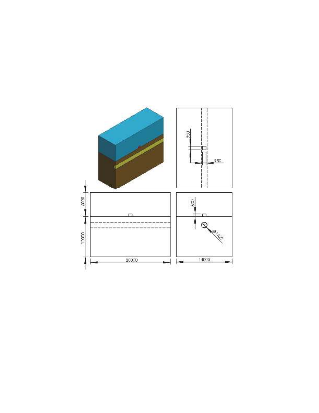
were considered in numerical models. In Fig. 1, longitudinal section and detailed dimensions of the
simulated model were shown for 900 kg explosive charge in different views. In this figure, natural gas,
air, soil, steel pipeline and explosive charge were shown with yellow, blue, brown, gray and red colors,
respectively.
Fig. 1. Longitudinal section and detailed dimensions of the simulated model (dimensions are in mm)
Grid generation
In simulations, air, soil, natural gas and explosive charge were modeled with Eulerian grids and the
governing equations were solved by the finite volume method. Also, the pipeline and concrete were
modeled with Lagrangian grids and the governing equations were solved by the finite element method.
Both Eulerian and Lagrangian domains were modeled with 8 node brick elements and the numbers of
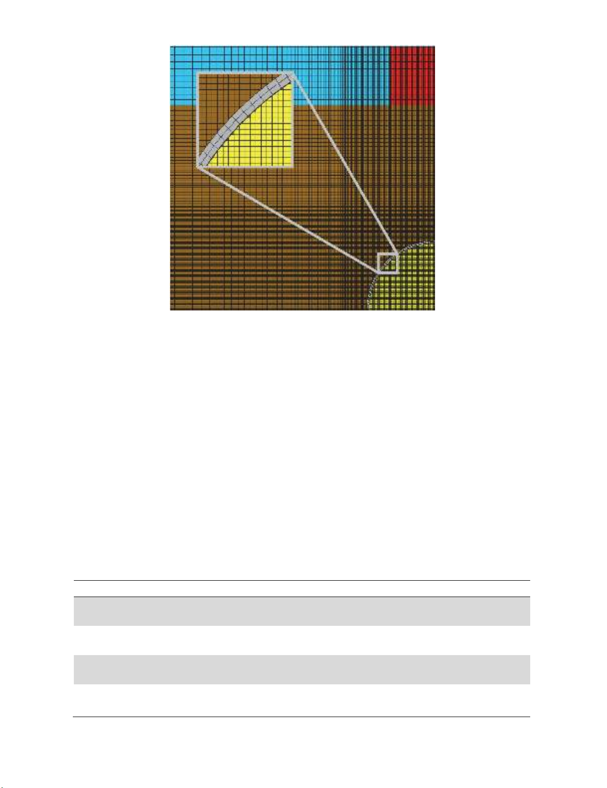
the grids were 3,481,600 and 177,280, respectively. To enhance the accuracy of numerical solutions
and due to the sharp gradients, finer grids (in order of 1 cm) were used for the area near the pipeline
and the soil between the explosive charge and pipeline. The grid sizes increased gradually in further
parts and the maximum grid size was about 70 cm. This issue is clearly illustrated in Fig. 2. In this
figure, grids in the transversal section were presented and the area near the pipeline elements was
magnified.
228
Fig. 2. Generated grids for 3-D model transversal section view and magnified view of pipeline elements
Boundary and initial conditions
Because of the symmetry in geometry and conditions, only a quarter of the domain was modeled, in
which
0x
and
0z
are the symmetry planes. In order to prevent reflection of pressure waves from
boundaries, the transmit boundary condition was considered in all boundaries. This boundary condition
enables the material pressure flowing out without being reflected back into the domain and is described
according to the Eq. (1) (Ambrosini & Luccioni, 2006):
for 0
for 0
ref n ref n
ref n
PUUI U
PPU
(1)
in which
n
U
and
P
are the normal velocity and pressure at boundary and ref
U
and ref
P
are the
reference velocity and pressure, respectively. Moreover,
I
is the material impedance, which is defined
as
I soundspeed
. Details of other boundary conditions and implemented areas are described in
Table 1. Also, initial conditions of the simulations were imposed according to the real case accidents.
In Table 2, details of the initial conditions are provided.
Table 1. Detailed descriptions of used boundary conditions (dimensions are in m)
BC Types Imposed Environments Implemented Areas Description
Symmetry Eulerian elements
Lagrangian elements
0, 0xz
Variables gradients in direction normal to
the planes are zero.
Outflow Eulerian elements
7, 10, 16xz y
Entry and exit of Eulerian materials are
allowed.
Clamp Lagrangian elements
10z
All elements of the velocity vector at the
boundary are zero.
Infinite Eulerian elements 16y
It is assumed that there are elements
outside the boundary which their values
are equal with values of inside elements.

O. Adibi et al. / Engineering Solid Mechanics 5 (2017)
229
Table 2. Detailed description of used initial conditions
IC Types Imposed Environments Implemented Materials Description
Pressure Eulerian elements Air and natural gas
The pressure of air is equal to ambient and
the pressure of natural gas is equal to the
working pressure of the pipeline (7 MPa).
Temperature Eulerian elements Air and natural gas Initial temperatures of Eulerian elements
are equal to ambient (305 K).
Velocity Eulerian elements Air Ambient air is supposed to be stationary.
Velocity Lagrangian elements Steal Initial velocity of Lagrangian parts are
zero.
2.2. Fluid–structure interaction
In problems that are engaged with the response of structures to explosions, fluid-structure
interactions (FSIs) play a major role in the accuracy of the results. In these problems, separate solutions
for the different physical fields (fluid and solid parts) are performed. At the boundary between fluids
and solids, information for the solution is shared between the two domains. This information can be
exchanged in one-way and two-way coupling methods. In the one-way-coupling method, the results of
fluid domain are used as external forces in solid parts, and displacement and deformation are computed.
This method needs low computational costs, but the accuracy of results can become enriched. In the
two-way coupling method that is further divided into weakly and strongly coupling methods, the
displacement and deformation of the structure are also applied to the fluid solver. In contrast, the two-
way coupling method is more accurate in obtaining results, but has high computational costs. In this
problem, to improve solution accuracy, fluid-structure interactions were applied according to
conditions of Table 3.
Table 3. Applied FSI conditions in the simulations
Interaction Boundaries Interaction Domains Coupling Method
Soil/pipeline Eulerian/Lagrangian Two-way/strongly-couple
d
Air/pipeline Eulerian/Lagrangian Two-way/strongly-coupled
Natural gas/pipeline Eulerian/Lagrangian Two-way/strongly-coupled
Pipeline/pipeline Lagrangian/Lagrangian Self-interaction/strongly-couple
d
2.3. Materials properties
In blast simulations, using appropriate numerical models for prediction of material properties is one
of the most important tips in achieving acceptable results. Material models should predict relationship
between pressure, stress, strain, specific volume (density), internal energy (temperature), resistance and
failure of material in different conditions. Materials used in this paper include air, natural gas, explosive
charge, steel, concrete and soil. Descriptions of numerical models for each material are expressed
separately in the following paragraphs.
Numerical model for air and natural gas
One of the simplest and most practical equations of state (EOS) is ideal gas relation that is used to
predict gases behaviors. This EOS is based on Boil and Gay-Lusaka laws and is shown in the Eq. (2)
(Cengel & Boles, 2015):
P
VnRT (2)
where P, V, n, R and T are the pressure, volume, number of moles, ideal gas constant and temperature,
respectively. In ideal gases, specific heat capacity only depends on temperature whereas in polytrophic
ideal gases, heat capacity is directly proportional with temperature. For this type of gases, pressure
relation with energy and therefore, temperature is according to the Eq. (3) (Cengel & Boles, 2015):
(1)eP
(3)


