
Chapter 5
The ATM Switch Model
The B-ISDN envisioned by ITU-T is expected to support a heterogeneous set of narrowband
and broadband services by sharing as much as possible the functionalities provided by a unique
underlying transport layer based on the ATM characteristics. As already discussed in
Section 1.2.1, two distinctive features characterize an ATM network: (i) the user information
is transferred through the network in small fixed-size packets, called
cells
1
, each 53 bytes long,
divided into a
payload
(48 bytes) for the user information and a
header
(5 bytes) for control data;
(ii) the transfer mode of user information is
connection-oriented
, that is cells are transferred onto
virtual links previously set up and identified by a label carried in the cell header. Therefore
from the standpoint of the switching functions performed by a network node, two different
sets of actions can be identified: operations accomplished at virtual call set up time and func-
tions performed at cell transmission time.
At call set-up time a network node receives from its upstream node or user-network inter-
face (UNI) a request to set up a virtual call to a given end-user with certain traffic
characteristics. The node performs a connection acceptance control procedure, not investi-
gated here, and if the call is accepted the call request is forwarded to the downstream node or
UNI of the destination end-user. What is important here is to focus on the actions executed
within the node in preparation of the next transfer of ATM cells on the virtual connection just
set up. The identifier of the virtual connection entering the switching node carried by the call
request packet is used as a new entry in the routing table to be used during the data phase for
the new virtual connection. The node updates the table by associating to that entry identifier a
new exit identifier for the virtual connection as well as the address of the physical output link
where the outgoing connection is being set up.
At cell transmission time the node receives on each input link a flow of ATM cells each
carrying its own virtual connection identifier. A table look-up is performed so as to replace in
1. The terms cell and packet will be used interchangeably in this section and in the following ones to
indicate the fixed-size ATM packet.
This document was created with FrameMaker 4.0.4
sw_mod Page 157 Tuesday, November 18, 1997 4:31 pm
Switching Theory: Architecture and Performance in Broadband ATM Networks
Achille Pattavina
Copyright © 1998 John Wiley & Sons Ltd
ISBNs: 0-471-96338-0 (Hardback); 0-470-84191-5 (Electronic)
158
The ATM Switch Model
the cell header the old identifier with the new identifier and to switch the cell to the switch
output link whose address is also given by the table.
Both
virtual channels
(VC) and
virtual paths
(VP) are defined as virtual connections between
adjacent routing entities in an ATM network. A logical connection between two end-users
consists of a series of virtual connections, if
n
switching nodes are crossed; a virtual path
is a bundle of virtual channels. Since a virtual connection is labelled by means of a hierarchical
key VPI/VCI (
virtual path identified/virtual channel identifier
) in the ATM cell header (see
Section 1.5.3), a switching fabric can operate either a full VC switching or just a VP switching.
The former case corresponds to a full ATM switch, while the latter case refers to a simplified
switching node with reduced processing where the minimum entity to be switched is a virtual
path. Therefore a VP/VC switch reassigns a new VPI/VCI to each virtual cell to be switched,
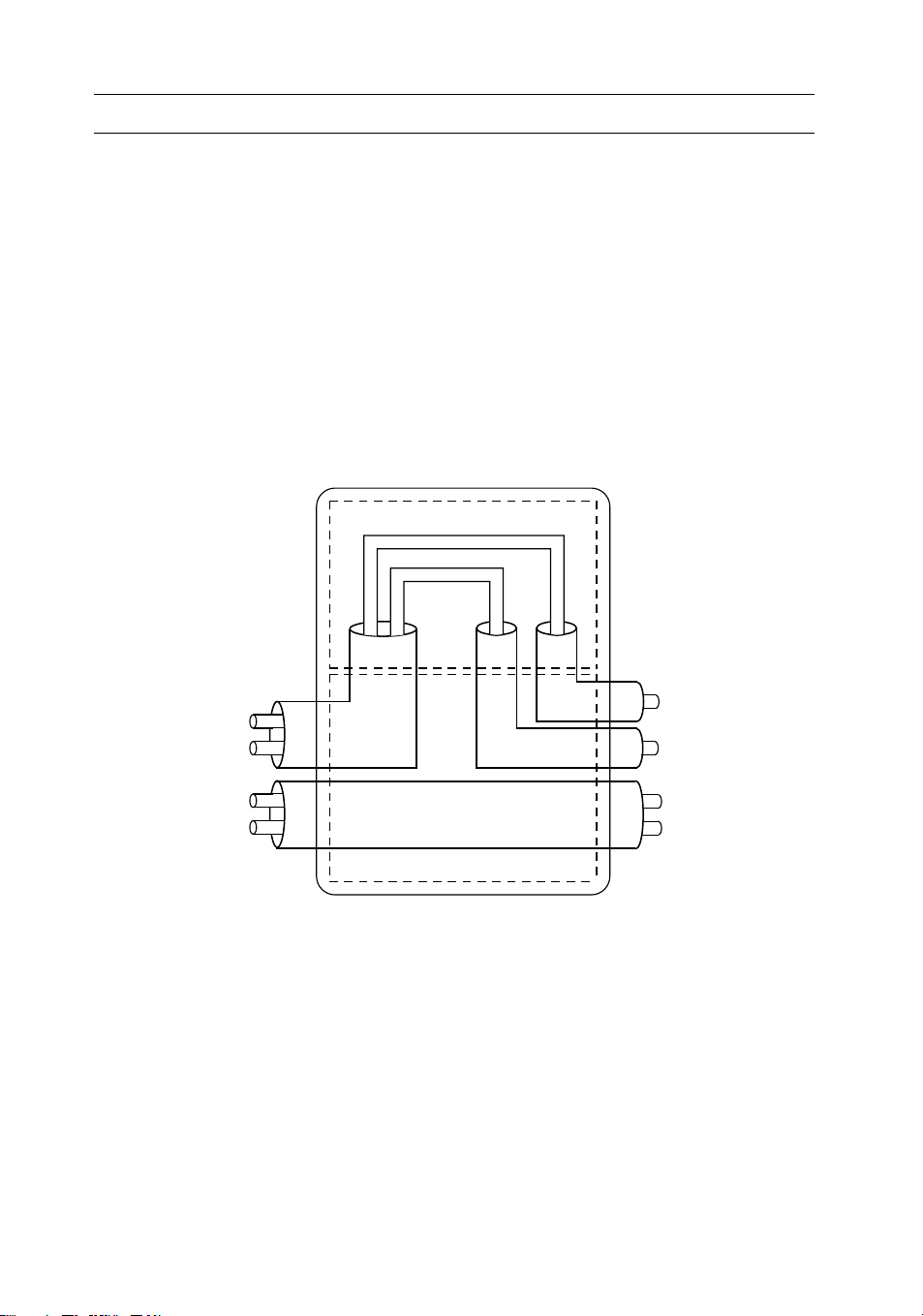
whereas only the VPI is reassigned in a VP switch, as shown in the example of Figure 5.1.
A general model of an ATM switch is defined in Section 5.1 on which the specific archi-
tectures described in the following sections will be mapped. A taxonomy of ATM switches is
then outlined in Section 5.2 based on the identification of the key parameters and properties
of an ATM switch.
Figure 5.1. VP and VC switching
n1+
VCI 1
VCI 2
VCI 2
VCI 4
ATM VP/VC switchig
VPI
1
VPI
3
VPI
7
VPI
2
VCI
2
VCI
1
VCI
6
VCI
1
VPI
1
VP switching
VC switching
VCI 1
VCI 6
VCI 2
VCI 4
sw_mod Page 158 Tuesday, November 18, 1997 4:31 pm

The Switch Model
159
5.1. The Switch Model
Research in ATM switching has been developed worldwide for several years showing the feasi-
bility of ATM switching fabrics both for small-to-medium size nodes with, say, up to a few
hundreds of inlets and for large size nodes with thousands of inlets. However, a unique taxon-
omy of ATM switching architectures is very hard to find, since different keys used in different
orders can be used to classify ATM switches. Very briefly, we can say that most of the ATM
switch proposals rely on the adoption for the
interconnection network
(IN), which is the switch
core, of multistage arrangements of very simple switching elements (SEs) each using the
packet
self-routing
concept. This technique consists in allowing each SE to switch (route) autono-
mously the received cell(s) by only using a self-routing tag preceding the cell that identifies the
addressed physical output link of the switch. Other kinds of switching architectures that are
not based on multistage structures (e.g., shared memory or shared medium units) could be
considered as well, even if they represent switching solutions lacking the scalability property. In
fact technological limitations in the memory access speed (either the shared memory or the
memory units associated with the shared medium) prevent “single-stage” ATM switches to be
adopted when the number of ports of the ATM switch overcomes a given threshold. For this
lack of generality such solutions will not be considered here. Since the packets to be switched
(the cells) have a fixed size, the interconnection network switches all the packets from the
inlets to the requested outlets in a time window called a
slot
, which are received aligned by the
IN. Apparently a slot lasts a time equal to the transmission time of a cell on the input and out-
put links of the switch. Due to this slotted type of switching operation, the non-blocking
feature of the interconnection network can be achieved by adopting either a rearrangeable net-
work (RNB) or a strict-sense non-blocking network (SNB). The former should be preferred
in terms of cost, but usually requires a more complex control.
We will refer here only to the cell switching of an ATM node, by discussing the operations
related to the transfer of cells from the inputs to the outputs of the switch. Thus, all the func-
tionalities relevant to the set-up and tear-down of the virtual connections through the switch
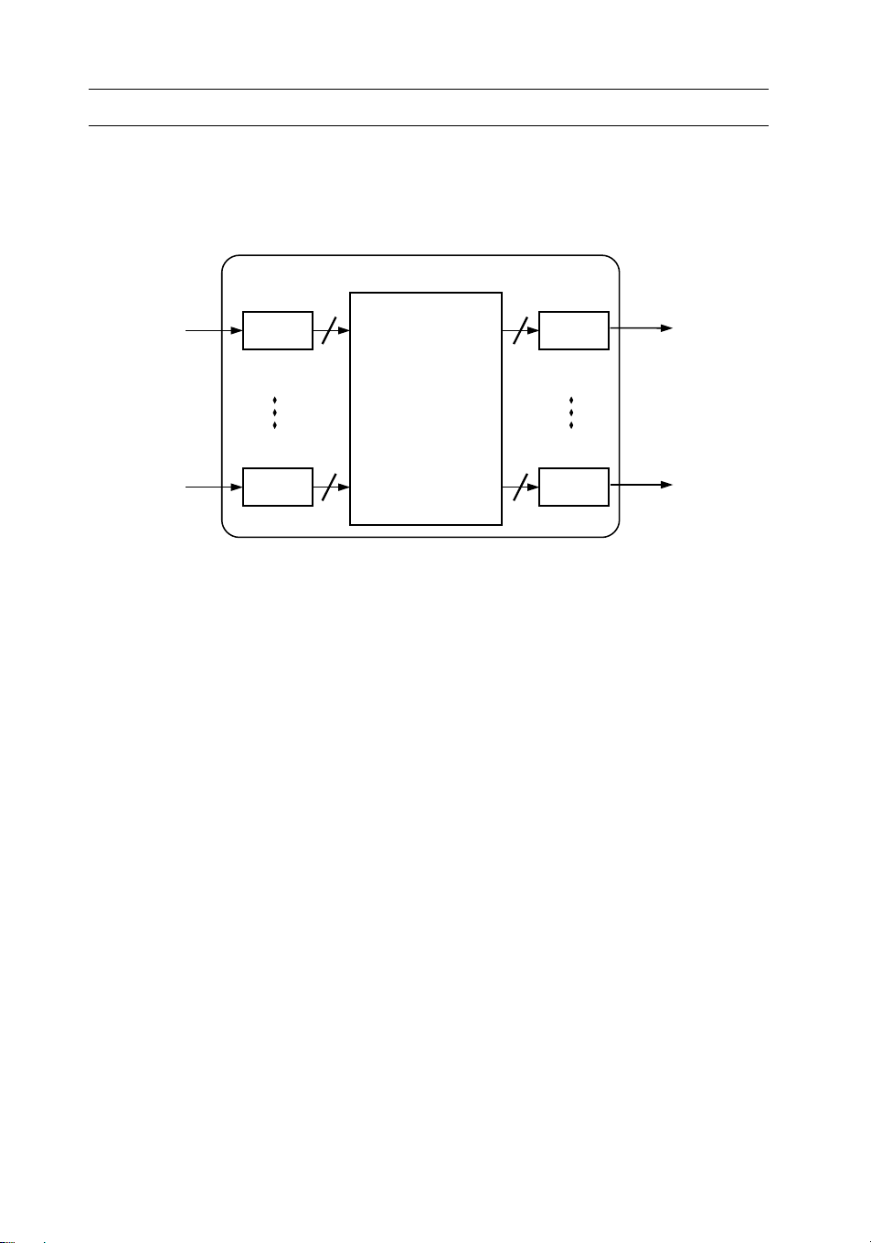
are just mentioned. The general model of a switch is shown in Figure 5.2. The refer-
ence switch includes
N input port controllers
(IPC),
N
output port controllers
(OPC) and an
interconnection network (IN). A very important block that is not shown in the figure is the
call processor
whose task is to receive from the IPCs the virtual call requests and to apply the
appropriate algorithm to decide whether to accept or refuse the call. The call processor can be
connected to IPCs either directly or, with a solution that is independent from the switch size,
through the IN itself. Therefore one IN outlet can be dedicated to access the call processor and
one IN inlet can be used to receive the cells generated by the call processor.
The IN is capable of switching up to cells to the same OPC in one slot, being
called an
output speed-up
since an internal bit rate higher than the external rate (or an equiva-
lent space division technique) is required to allow the transfer of more than one cell to the
same OPC. In certain architectures an
input speed-up
can be accomplished, meaning that
each IPC can transmit up to cells to the IN. If , that is there is no input speed-up,
the output speed-up will be simply referred to as
speed-up
and denoted as
K.
The IN is usually
a multistage arrangement of very simple SEs, typically , which either are provided with
internal queueing (
SE queueing
), which can be realized with input, output or shared buffers, or
NN×
KoKo
Ki
KiKi1=
22×
sw_mod Page 159 Tuesday, November 18, 1997 4:31 pm
160
The ATM Switch Model
are unbuffered (
IN queueing
). In this last case input and output queueing, whenever adopted,
take place at IPC and OPC, respectively, whereas shared queueing is accomplished by means
of additional hardware associated with the IN.
In general two types of conflict characterize the switching operation in the interconnection
network in each slot, the
internal conflict
s and the
external conflicts
. The former occur when two
I/O paths compete for the same internal resource, that is the same interstage link in a multi-
stage arrangement, whereas the latter take place when more than
K
packets are switched in the
same slot to the same OPC (we are assuming for simplicity ). An ATM interconnec-
tion network with speed-up
K
is said to be non-blocking (
K
-rearrangeable
according to the definition given in Section 3.2.3) if it guarantees absence of internal conflicts
for any arbitrary switching configuration free from external conflicts for the given network
speed-up value
K
. That is a non-blocking IN is able to transfer to the OPCs up to
N
packets
per slot, in which at most
K
of them address the same switch output. Note that the adoption
of output queues either in an SE or in the IN is strictly related to a full exploitation of the
speed-up: in fact, a structure with does not require output queues, since the output
interface is able to transmit downstream one packet per slot. Whenever queues are placed in
different elements of the ATM switch (e.g., SE queueing, as well as input or shared queueing
coupled with output queueing in IN queueing), two different internal transfer modes can be
adopted:
•
backpressure
(BP), in which by means of a suitable backward signalling the number of pack-
ets actually switched to each downstream queue is limited to the current storage capability
of the queue; in this case all the other head-of-line (HOL) cells remain stored in their
respective upstream queue;
•
queue loss
(QL), in which cell loss takes place in the downstream queue for those HOL
packets that have been transmitted by the upstream queue but cannot be stored in the
addressed downstream queue.
Figure 5.2. Model of ATM switch
0
N-1
0
N-1 Ko
Ko
IPC OPC
IN
Ki
Ki
Ki1=
NN×KN≤()
K1=
sw_mod Page 160 Tuesday, November 18, 1997 4:31 pm

The Switch Model
161
The main functions of the port controllers are:
•
rate matching between the input/output channel rate and the switching fabric rate;
•
aligning cells for switching (IPC) and transmission (OPC) purposes (this requires a tempo-
rary buffer of one cell);
•
processing the cell received (IPC) according to the supported protocol functionalities at the
ATM layer; a mandatory task is the
routing
(switching) function, that is the allocation of a
switch output and a new VPI/VCI to each cell, based on the VCI/VPI carried by the
header of the received cell;
•
attaching (IPC) and stripping (OPC) a self-routing label to each cell;
•
with IN queueing, storing (IPC) the packets to be transmitted and probing the availability
of an I/O path through the IN to the addressed output, by also checking the storage capa-
bility at the addressed output queue in the BP mode, if input queueing is adopted; queue-
ing (OPC) the packets at the switch output, if output queueing is adopted.
An example of ATM switching is given in Figure 5.3. Two ATM cells are received by the
ATM node
I
and their VPI/VCI labels,
A
and
C
, are mapped in the input port controller onto
the new VPI/VCI labels
F
and
E
; the cells are also addressed to the output links
c
and
f
, respec-
tively. The former packet enters the downstream switch
J
where its label is mapped onto the
new label
B
and addressed to the output link
c
. The latter packet enters the downstream node
K
where it is mapped onto the new VPI/VCI
A
and is given the switch output address
g
. Even
if not shown in the figure, usage of a self-routing technique for the cell within the intercon-
nection network requires the IPC to attach the address of the output link allocated to the
virtual connection to each single cell. This self-routing label is removed by the OPC before the
cell leaves the switching node.
The traffic performance of ATM switches will be analyzed in the next sections by referring
to an offered
uniform random traffic
in which:
•
packet arrivals at the network inlets are independent and identically distributed Bernoulli
processes with
p
indicating the probability that a network inlet receives a
packet in a generic slot;
•
a network outlet is randomly selected for each packet entering the network with uniform
probability .
Note that this rather simplified pattern of offered traffic completely disregards the application
of connection acceptance procedure of new virtual calls, the adoption of priority among traffic
classes, the provision of different grade of services to different traffic classes, etc. Nevertheless,
the uniform random traffic approach enables us to develop more easily analytical models for an
evaluation of the traffic performance of each solution compared to the others. Typically three
parameters are used to describe the switching fabric performance, all of them referred to
steady-state conditions for the traffic:
•
Switch throughput
ρ
: the normalized amount of traffic carried by the switch
expressed as the utilization factor of its input links; it is defined as the probability that a
packet received on an input link is successfully switched and transmitted by the addressed
switch output; the maximum throughput , also referred to as
switch capacity
, indicates
the load carried by the switch for an offered load .
0p1≤<()
1N⁄
0ρ1≤<()
ρmax
p1=
sw_mod Page 161 Tuesday, November 18, 1997 4:31 pm
![Các thiết bị đo lường cơ bản: Nguyên lý hoạt động [Chuẩn nhất]](https://cdn.tailieu.vn/images/document/thumbnail/2019/20190309/quocthaitn/135x160/7901552107683.jpg)
![Đèn Led: Hiệu suất năng lượng [TỐT NHẤT]](https://cdn.tailieu.vn/images/document/thumbnail/2018/20180920/khuong-elink/135x160/8601537423106.jpg)
![Mạch điện tử hay ứng dụng cho thực tế: Tổng hợp một số mạch [mới nhất]](https://cdn.tailieu.vn/images/document/thumbnail/2015/20151120/caotan1422/135x160/284835042.jpg)
![50 mạch điện tử cảm biến [tốt nhất/ phổ biến]](https://cdn.tailieu.vn/images/document/thumbnail/2015/20151120/caotan1422/135x160/459492351.jpg)
![OrCAD Capture 9.2: Chương 3 [Hướng Dẫn Chi Tiết]](https://cdn.tailieu.vn/images/document/thumbnail/2015/20150321/taikhoantatca/135x160/1748098_157.jpg)


%20--%3e%3cdefs%3e%3cstyle%3e%20.st0%20{%20fill:%20%23fff;%20}%20.st1%20{%20fill:%20%237800fa;%20}%20%3c/style%3e%3c/defs%3e%3cpath%20class='st1'%20d='M117.78,12.18H43.11c2.9,3.47,4.65,7.94,4.65,12.82,0,5.6-2.3,10.66-6.01,14.29h76.02l7.22-13.56-7.22-13.56Z'/%3e%3cg%3e%3cpath%20class='st0'%20d='M53.58,26.17h-.59v-1.46h.59v-4.96h2.83c1.78,0,2.67.94,2.67,2.82v5.76c0,1.87-.89,2.81-2.67,2.81h-2.83v-4.96ZM55.36,21.37v3.34h1.1v1.46h-1.1v3.34h1.01c.61,0,.91-.37.91-1.1v-5.93c0-.74-.3-1.1-.91-1.1h-1.01Z'/%3e%3cpath%20class='st0'%20d='M65.99,31.14h-1.8l-.31-2.07h-2.19l-.31,2.07h-1.64l1.82-11.39h2.62l1.82,11.39ZM65.28,18.04c-.25.46-.51.77-.75.94-.21.15-.47.22-.79.22-.26,0-.57-.07-.92-.22l-.38-.15c-.14-.05-.26-.07-.37-.07-.3,0-.53.18-.71.54l-.91-.68c.25-.46.51-.77.75-.94.21-.14.48-.21.79-.21.26,0,.57.07.92.21l.38.15c.14.05.26.07.37.07.3,0,.53-.18.71-.54l.91.68ZM61.91,27.52h1.73l-.87-5.76-.87,5.76Z'/%3e%3cpath%20class='st0'%20d='M74.53,26.89v1.52c0,1.91-.89,2.86-2.67,2.86s-2.67-.95-2.67-2.86v-5.93c0-1.91.89-2.86,2.67-2.86s2.67.95,2.67,2.86v1.11h-1.69v-1.22c0-.75-.31-1.12-.93-1.12s-.93.37-.93,1.12v6.15c0,.74.31,1.11.93,1.11s.93-.37.93-1.11v-1.63h1.69Z'/%3e%3cpath%20class='st0'%20d='M81.4,31.14h-1.8l-.31-2.07h-2.19l-.31,2.07h-1.64l1.82-11.39h2.62l1.82,11.39ZM75.9,19.2l1.52-1.91h1.71l1.51,1.91h-1.61l-.76-.95-.75.95h-1.61ZM77.32,27.52h1.73l-.87-5.76-.87,5.76ZM83.1,15.99l-1.76,1.91h-1.26l1.17-1.91h1.86Z'/%3e%3cpath%20class='st0'%20d='M84.86,19.75c1.78,0,2.67.94,2.67,2.82v1.48c0,1.87-.89,2.81-2.67,2.81h-.85v4.28h-1.79v-11.39h2.64ZM84.01,21.37v3.86h.85c.58,0,.87-.36.87-1.08v-1.71c0-.71-.29-1.07-.87-1.07h-.85Z'/%3e%3cpath%20class='st0'%20d='M93.51,19.75c1.78,0,2.67.94,2.67,2.82v1.48c0,1.87-.89,2.81-2.67,2.81h-.85v4.28h-1.79v-11.39h2.64ZM92.66,21.37v3.86h.85c.58,0,.87-.36.87-1.08v-1.71c0-.71-.29-1.07-.87-1.07h-.85Z'/%3e%3cpath%20class='st0'%20d='M98.8,31.14h-1.79v-11.39h1.79v4.88h2.03v-4.88h1.83v11.39h-1.83v-4.88h-2.03v4.88Z'/%3e%3cpath%20class='st0'%20d='M105.36,24.55h2.46v1.62h-2.46v3.34h3.09v1.63h-4.88v-11.39h4.88v1.63h-3.09v3.18ZM108.17,17.29l-1.76,1.91h-1.26l1.17-1.91h1.86Z'/%3e%3cpath%20class='st0'%20d='M112.2,19.75c1.78,0,2.67.94,2.67,2.82v1.48c0,1.87-.89,2.81-2.67,2.81h-.85v4.28h-1.79v-11.39h2.64ZM111.35,21.37v3.86h.85c.58,0,.87-.36.87-1.08v-1.71c0-.71-.29-1.07-.87-1.07h-.85Z'/%3e%3c/g%3e%3ccircle%20class='st1'%20cx='25'%20cy='25'%20r='20'/%3e%3cpath%20class='st0'%20d='M32.78,19.27c2.92,0,4.43,2.55,5.28,5.33l.71,2.17c.14.38-.33.75-.71.75h-5.61c.19-.33.24-.71.09-1.08l-.75-2.45c-.43-1.32-.99-2.64-1.79-3.77.75-.57,1.65-.94,2.78-.94h0ZM25,18.38c3.25,0,4.9,2.78,5.89,5.89l.76,2.45c.14.42-.33.8-.8.8h-11.69c-.42,0-.94-.38-.8-.8l.75-2.45c.99-3.11,2.64-5.89,5.89-5.89h0ZM25,11.35c1.74,0,3.11,1.37,3.11,3.11s-1.37,3.11-3.11,3.11-3.11-1.41-3.11-3.11,1.41-3.11,3.11-3.11h0ZM17.27,19.27c1.08,0,1.98.38,2.73.94-.8,1.13-1.37,2.45-1.74,3.77l-.8,2.45c-.14.38-.05.75.09,1.08h-5.56c-.42,0-.9-.38-.75-.75l.71-2.17c.9-2.78,2.41-5.33,5.33-5.33h0ZM17.27,12.91c1.51,0,2.78,1.27,2.78,2.83s-1.27,2.83-2.78,2.83-2.83-1.27-2.83-2.83,1.27-2.83,2.83-2.83h0ZM32.78,12.91c1.56,0,2.78,1.27,2.78,2.83s-1.23,2.83-2.78,2.83-2.83-1.27-2.83-2.83,1.27-2.83,2.83-2.83h0ZM27.07,28.56v.09c0,.57-.24,1.08-.61,1.46h0v.05c-.38.33-.9.57-1.46.57s-1.08-.24-1.46-.61h0c-.38-.38-.61-.9-.61-1.46v-.09h1.41v.09c0,.19.05.38.19.47v.05c.09.09.28.19.47.19s.38-.09.47-.19v-.05c.14-.09.24-.28.24-.47t-.05-.09h1.41ZM30.99,28.56v.09c0,1.65-.66,3.16-1.74,4.24-1.08,1.08-2.59,1.79-4.24,1.79s-3.16-.71-4.24-1.79l-.05-.05c-1.04-1.08-1.7-2.55-1.7-4.2v-.09h1.41v.09c0,1.27.47,2.4,1.27,3.25h.05c.85.85,1.98,1.37,3.25,1.37s2.4-.52,3.25-1.37c.85-.8,1.37-1.98,1.37-3.25v-.09h1.37ZM34.99,28.56v.09c0,2.78-1.13,5.28-2.92,7.07-1.79,1.79-4.29,2.92-7.07,2.92s-5.23-1.13-7.07-2.92c-1.79-1.79-2.92-4.29-2.92-7.07v-.09h1.41v.09c0,2.4.94,4.53,2.5,6.08,1.56,1.56,3.72,2.5,6.08,2.5s4.52-.94,6.08-2.5c1.56-1.56,2.5-3.68,2.5-6.08v-.09h1.41Z'/%3e%3c/svg%3e)