ISSN: 2615-9740
JOURNAL OF TECHNICAL EDUCATION SCIENCE
Ho Chi Minh City University of Technology and Education
Website: https://jte.edu.vn
Email: jte@hcmute.edu.vn
JTE, Volume 20, Issue 01, 02/2025
62
Enhanced Teleoperation and Visual-Force Feedback with Obstacle Avoidance
for a Car-like Mobile Robot based on WAN Network Architecture
Duc Thien Tran*, Hoang Quan Vo , Trung Kien Nguyen , Thanh Nha Nguyen
Ho Chi Minh City University of Technology and Education, Vietnam
*Corresponding author. Email: thientd@hcmute.edu.vn
ARTICLE INFO
ABSTRACT
22/05/2024
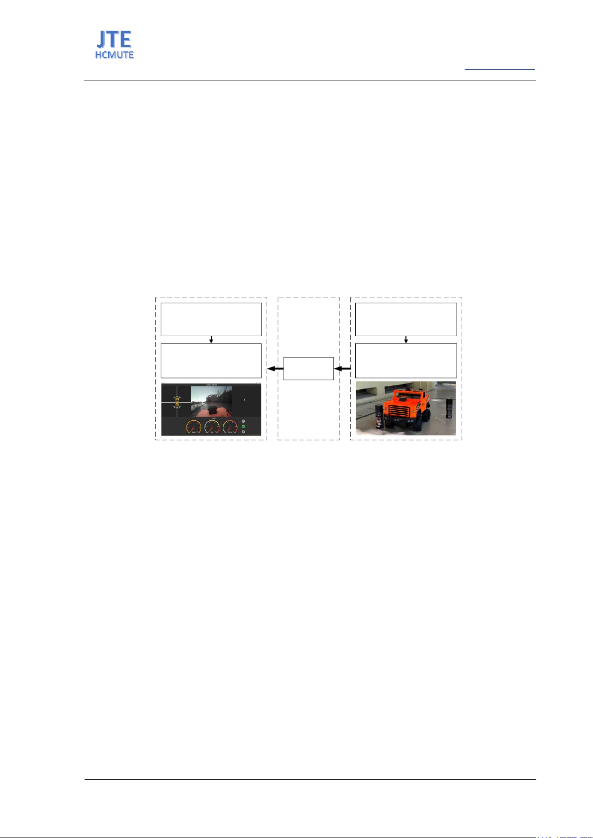
This paper presents an enhanced teleoperation system and visual-force
feedback with obstacle avoidance for a Car-like mobile robot. The
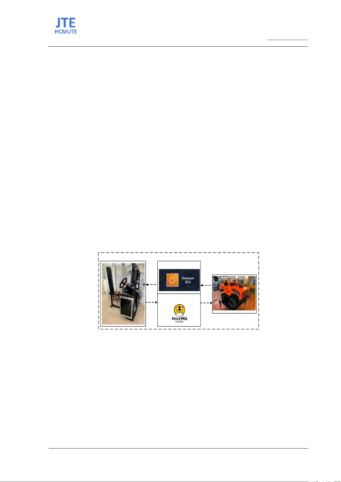
proposed system includes a local station, a remote station, and a
communication channel. The local station allows the operator to give
acceleration, orientation, and driving mode commands. It generates the
haptic effect of the obstacles in the remote station for the operator due to
the visual-force feedback. The remote station is a Car-like mobile robot
executing control commands from the local station and providing feedback
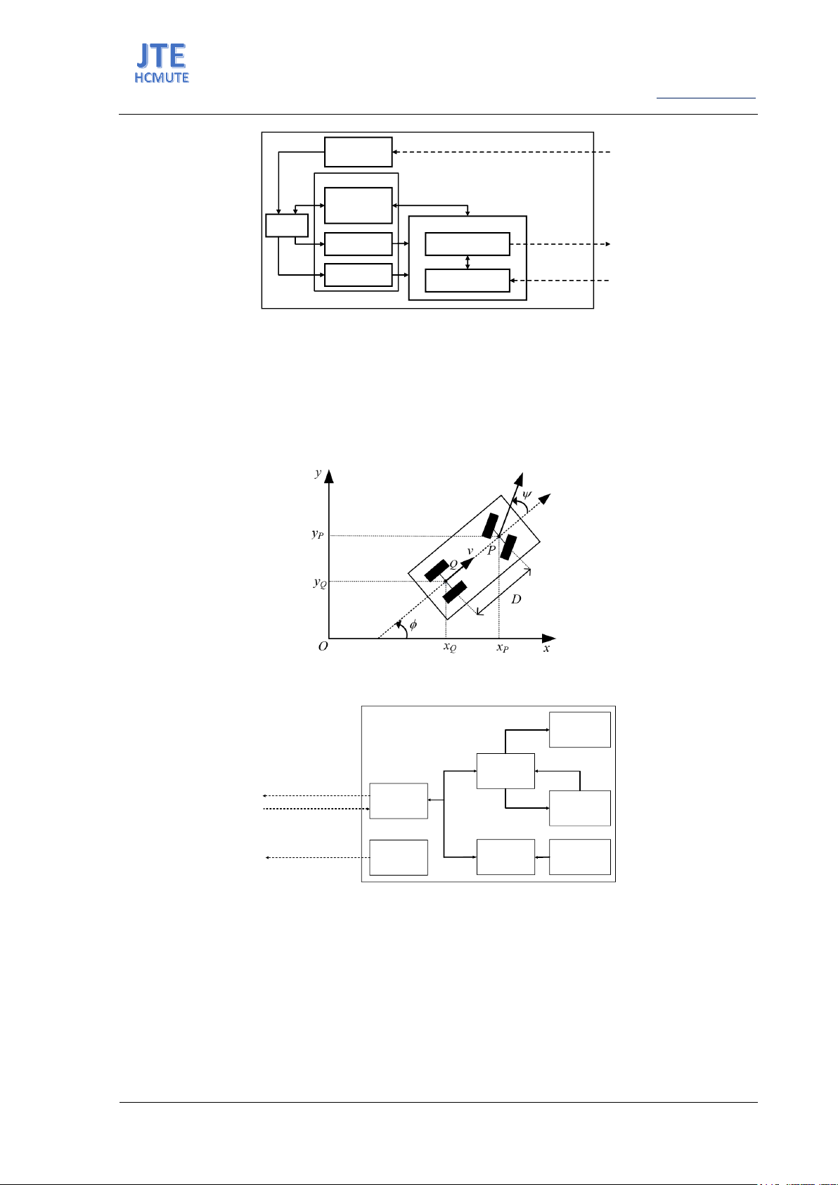
on the working status of the robot. Moreover, the robot has the ability of
obstacle avoidance through the Potential Field (PF) algorithm with input
signals being the distance from the robot to obstacles and a virtual repulsive
force that influences both the steering angle of the robot and the haptic
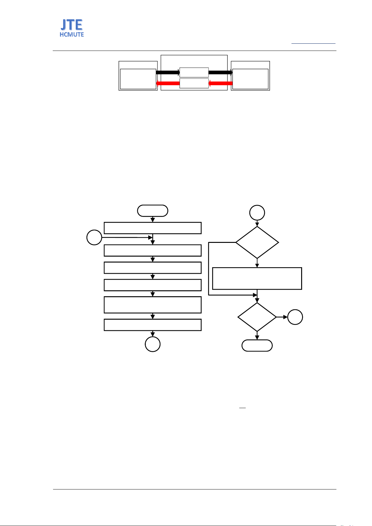
steering wheel system. The communication channel will connect the local
station and the remote station wirelessly based on Wide Area Network
(WAN) architecture with the Message Queuing Telemetry Transport
(MQTT) to resolve complex problems such as control distance, latency,
etc. Several case studies are used to evaluate the efficacy of providing the
operator with haptic and visual feedback at any control distance.
20/07/2024
23/07/2024
28/02/2025
KEYWORDS
Car-like mobile robot;
Wide Area Network (WAN);
Teleoperation control;
Message Queuing Telemetry Transport
(MQTT);
Obstacle avoidance.
Doi: https://doi.org/10.54644/jte.2025.1601
Copyright © JTE. This is an open access article distributed under the terms and conditions of the Creative Commons Attribution-NonCommercial 4.0
International License which permits unrestricted use, distribution, and reproduction in any medium for non-commercial purpose, provided the original work is
properly cited.
1. Introduction
The advancement of technology is leading to an increased utilization of mobile robots in various
fields and tasks, replacing human involvement. Two common control methods that many researchers
focus on are autonomous navigation [1] and teleoperation control [2], each having its advantages and
disadvantages. The Society of Automotive Engineers (SAE) defines five levels of autonomy for Car-
like mobile robots. Achieving complete human intervention-free operation, known as level five (fully
autonomous), comes with high computational costs. Fully autonomous systems [3] require sophisticated
algorithms for precise control, and dealing with dynamic environments makes them less reliable without
human intervention. For tasks requiring high precision, like search and rescue [4] operations or in
agriculture [5] with constantly changing conditions, fully autonomous navigation faces significant
challenges. As a result, recent developments focus on and continuously improve remote control systems
for mobile robots.
Remote control systems for mobile robots allow humans to perceive the environment surrounding
the robot from a distance and provide control commands. The main advantage of this system is enhanced
work efficiency, which leverages human intelligence and experience while ensuring the absence of the
controller in the working environment of the robot. However, the system is limited by communication
accuracy, which depends on the control distance and system latency [6]. Additionally, human perception
limitations regarding the working environment of the robot pose challenges in control. An Internet-based
control system was employed for a wireless mobile robot, utilizing the Common Object Request Broker
Architecture (CORBA) communication framework for remote control [7]. However, the system lacked
a control chamber, hindering operators from gathering environmental data crucial for decision-making.
Another mobile robot was operated via Radio Frequency (RF) waves, with interaction facilitated through
a control interface [8]. But the operators encountered challenges due to the sole reliance on a button-
ISSN: 2615-9740
JOURNAL OF TECHNICAL EDUCATION SCIENCE
Ho Chi Minh City University of Technology and Education
Website: https://jte.edu.vn
Email: jte@hcmute.edu.vn
JTE, Volume 20, Issue 01, 02/2025
63
based interface without peripheral devices or sensory feedback. A Car-like mobile robot incorporated
force feedback via tactile sensors and employed the Zigbee protocol for remote control [9]. This
configuration enabled the driver of haptic feedback to avoid collisions. Nevertheless, these projects still
faced with limitations such as restricted control range, limited visibility of the environment, and the
absence of safety features for operators. From the limitations of the previous studies came the motivation
for this paper to propose a combined approach to optimize the operation of mobile robots.
Based on the above analysis, this paper proposes a remote control system for car-like mobile robots
over the WAN. The proposed system is designed with a local station and a remote station which is a
car-like mobile robot. The high-level communication protocol MQTT is used for communication
between the two entities on a cloud computing platform, 4 Generation (4G) Long Term Evolution (LTE),
and Wireless Fidelity (Wifi). This allows the control range to be extended to the global level as long as
the system is connected to the Internet. A force feedback steering wheel, a visual feedback user interface,
and an obstacle avoidance feature based on the PF algorithm are also developed to enhance the
controllability of the driver. Finally, experiments were conducted to evaluate the responsiveness of the
system and the effectiveness of the method in terms of user controllability.
The remainder of this paper is structured as follows: section 2 provides an overview of the system,
including four parts: local station, remote station, communication channel, and visual-force feedback.
Section 3, the main part of this document, discusses the communication protocol between the local and
remote stations. In Section 4, detailed explanations of the control methods at the local and remote
stations are provided. Experimental cases of the remote control system are presented in Section 5.
Section 6 provides the conclusion of this paper.
2. System description
The proposed system consists of two main components: the remote station and the local station. Both
of them connect through a communication channel built as a WAN [10]. MQTT protocol is used to
transfer data between the local station and the remote station [11]. The relationship between these two
entities is illustrated in Figure 1.
REMOTE STATION
COMMUNICATION CHANNEL
MQTT Broker 1
MQTT Broker 2
LOCAL STATION
Figure 1. Overview of the teleoperation car system
2.1. Local station
The local station as depicted in Figure 2 is a stationary system designed for a user to control a mobile
robot at the remote station through mechanisms similar to a car, including a human, haptic steering
system, pedal sensor, mode stick, Graphic User Interface (GUI), and Electronic Control Units (ECU).
The human gives the commands control to the ECU through the actuators. The ECU has two ESP32
modules: Master and Slave module. The Master module receives the commands control, and then
encodes this commands into a message packet, and sends it to Broker 1. Besides that, the Master module
is also involved in controlling the force feedback motor on the steering wheel thanks to the PF algorithm.
The Slave module is used to receive feedback signals from the distance sensors of the remote station
through Broker 1 and send them to the Master module for collision warning force feedback purposes.
Additionally, a GUI display real-time images and sensor data of the robot from a remotely working
environment for operators. The proposed system operates as a closed-loop system with the feedback
signal from the camera module and distance sensors.
ISSN: 2615-9740
JOURNAL OF TECHNICAL EDUCATION SCIENCE
Ho Chi Minh City University of Technology and Education
Website: https://jte.edu.vn
Email: jte@hcmute.edu.vn
JTE, Volume 20, Issue 01, 02/2025
64
Graphic User
Interface
Human
Haptic
Steering
System
Mode Stick
Pedal Sensor
Electronic Control Units
Master Module
Slave Module
Publish to
Broker 1
Subcribe from
Broker 1
Local Station
Subcribe from Broker 2
Actuators
Figure 2. Local station architecture
2.2. Remote station
The remote station is a Car-like mobile robot remotely controlled from a specific distance. Consider
a model similar to a car, as shown in Figure 3, with four wheels divided into two parts. The first part
consists of two rear wheels fixed in parallel to the body of the vehicle. The remaining part includes two
front steering wheels also parallel to each other. It can turn left or right at an angle but cannot
immediately move sideways. Therefore, it is known as a non-holonomic system.
Figure 3. The Car-like mobile robot kinematic model
MASTER
MODULE
REMOTE STATION
SLAVE1
MODULE
SLAVE2
MODULE
RC
SERVO
DC
MOTOR
Can bus
Can bus
CAMERA
MODULE
PUBLISH TO
BROKER 1
SUBCRIBE FROM
BROKER 1
PUBLISH TO
BROKER 2
DISTANCE
SENSORS
Encoder signal
Figure 4. Remote station architecture
In this study, the detailed structure of the Car-like mobile robot is presented in Figure 4. This system
included modules: Master, Slave1, Slave2, Camera, RC servo, DC motor, and distance sensors. Firstly,
the Master module receives and decodes message packets from the local station through Broker1. After
that, the Master module sends control signals to the Slave1 module for controlling the steering angle by
RC servo and car speed by DC motor. Simultaneously, the Slave1 module reads the encoder signal of
the DC motor to regulate the DC motor speed by the Proportional Integral Derivative (PID) controller.
Lastly, the Slave2 module reads and then sends distance sensor data to the Master module. Both of the
slave modules communicate with the Master module through a local network system called the Control
Area Network (CAN) to ensure stability.
ISSN: 2615-9740
JOURNAL OF TECHNICAL EDUCATION SCIENCE
Ho Chi Minh City University of Technology and Education
Website: https://jte.edu.vn
Email: jte@hcmute.edu.vn
JTE, Volume 20, Issue 01, 02/2025
65
2.3. Communication channel
The global internet network serves as the wireless data transmission environment between the control
station and the mobile robot based on the Transmission Control Protocol/Internet Protocol (TCP/IP)
platform. The system is structured like a WAN, where the control station is Local Area Network (LAN)
1, and the mobile robot is LAN 2. Due to the mobility nature, a wireless cellular network is employed
on the mobile robot, while a wireless wifi network is used at the control station. However, to ensure
stability, optimization, and data security of the transmission, a high-level communication protocol
MQTT is integrated.
2.4. Visual-force feedback
Image data feedback from the surrounding environment of the robot in a remote setting is collected
through a built-in camera within the Car-like mobile robot. Subsequently, the data is processed,
compressed, and transmitted to the control station. The received image data is then encoded, and the
frame size is adjusted to match the user interface for visual feedback purposes. Information regarding
obstacles is also gathered and displayed on the user interface as in Figure 5.
GUI in Local Station Camera in Remote StationMQTT Broker 2
TOPIC_03
Extract, encode image
and display on GUI
Collect image data from
envinronment and
storage it
Convert image data to
MQTT message, upload
it to MQTT Broker
Receive image data
from Remote station
through MQTT Broker
Figure 5. Visual feedback on GUI in the local station
The force feedback data is calculated based on distance data obtained in the working environment of
the robot through ultrasonic sensors. Using the PF algorithm, the force coefficient is encoded into the
feedback packet sent to the local station after the computation. Depending on the received force
coefficient value, the force feedback on the steering wheel system will generate a haptic effect to alert
the operator about obstacles ahead of the robot.
3. MQTT protocol
The MQTT protocol is designed to operate on unreliable and low-bandwidth networks, allowing IoT
devices to send and receive messages with low latency, minimal resource consumption, and long
distances between devices. As a high-level communication protocol, MQTT requires devices
exchanging data to establish a proper sequence to ensure both data security and transmission speed.
In the proposed system, two intermediary MQTT broker servers have been established for the dual
purposes of transmitting and receiving images and controlling commands, as well as receiving feedback
information. These brokers are created by using the services of two different cloud computing providers:
Amazon Web Services (AWS) for image data and HiveMQ for control and feedback data, aiming to
optimize service costs.
3.1. MQTT protocol for transmitting controlling commands and receiving feedback data
HiveMQ broker is used for transmitting control commands and receiving feedback data. Establishing
a two-way packet exchange between the control station and the mobile robot is necessary for both
systems to participate in the MQTT protocol. The local station plays the role of client 1, remote station
is client 2. They are both set up into two topics as subscriber and publisher as in Figure 6.
ISSN: 2615-9740
JOURNAL OF TECHNICAL EDUCATION SCIENCE
Ho Chi Minh City University of Technology and Education
Website: https://jte.edu.vn
Email: jte@hcmute.edu.vn
JTE, Volume 20, Issue 01, 02/2025
66
TOPIC_01
Client 1 Publish Subcribe
Local station
SERVER
MODULE
MQTT Broker Client 1
Remote station
SERVER
MODULE
TOPIC_02 PublishSubcribe
Figure 6. MQTT Broker in HiveMQ Cloud
3.2. MQTT protocol for visual feedback
To obtain live image data from the operating environment of the robot, the ESP32 Cam module was
employed. This module is connected to the internet via a 4G cellular network, compressing the data and
sending it to the MQTT broker. AWS cloud computing service is utilized for fast and accurate
transmission of large-sized image data. The remote station plays the role of client 1 and publishes data
to topic 1 of the MQTT broker. The GUI at the local station plays the role of client 2, subscribes to topic
1, and receives feedback data.
4. Control method
4.1. Local station
The flowchart presents the local station principle as in Figure 7.
START
MASTER CONNECT TO BROKER1
MASTER COLLECT THE EXECUTIVE SIGNAL
FROM MODE STICK
MASTER COLLECT THE EXECUTIVE SIGNAL
FROM HAPTIC STEERING SYSTEM
MASTER COLLECT THE EXECUTIVE SIGNAL
FROM GAS PENDAL
MASTER PACKET COMMANDS MESSAGE
AND PUBLISH TO BROKER1 FOR REMOTE
STATION
MASTER RECEIVE FEEDBACK MESSAGE OF
REMOTE STATION FROM BROKER1
RPF != 0 ? &&
direction !=0 ?
TO REFER TO THE REPULSIVE
POTENTIAL FIELD VALUE TO
INFLUENCE TO THE STEERING WHEEL
ANGLE
END
POWER ON ? YES
YES
NO
NO
2
2
1
1
Figure 7. The flowchart of the local station
At the local station, a linear PID controller, represented by the formula (1), is employed to control
the regeneration of the steering force and provide straight-line feedback to the steering wheel through
two Direct Current (DC) motors.
11
1
1 1 1 1
0
( ) ( ) ( ) ( )
t
p i d d
u t K e t K e d K e t
dt

(1)
Where
1
e
is the tracking error of the system (degree),
1
p
K
is the proportional gain,
1
i
K
is the internal
gain,
1
d
K
is the derivative gain, and t is the sampling time for the system(s).
The tracking error of the system is defined as:
1d
e q q
(2)