
http://www.iaeme.com/IJMET/index.asp 172 editor@iaeme.com
International Journal of Mechanical Engineering and Technology (IJMET)
Volume 10, Issue 03, March 2019, pp. 172–177, Article ID: IJMET_10_03_017
Available online at http://www.iaeme.com/ijmet/issues.asp?JType=IJMET&VType=10&IType=3
ISSN Print: 0976-6340 and ISSN Online: 0976-6359
© IAEME Publication Scopus Indexed
NUMERICAL SIMULATION OF FREE AND
FORCED OSCILLATIONS FOR PENDULUM
TYPE CHILD TRAVEL SEAT
N. L. Pavlov, E. E. Sokolov, M. H. Peychev and D. I. Dacova
Department of Combustion Engines, Automobile Engineering and Transport,
Faculty of Transport,
Technical University of Sofia, 8 Kliment Ohridski Blvd., 1000 Sofia, Bulgaria
ABSTRACT
This paper presents a dynamic model of a tilting child travel seat. The child seat is
presented as a physical pendulum. Thereby the seat in concert with the child can
rotate around a cylindrical joint located above its mass center. This way the lateral
acceleration acting on the child travelling in a cornering vehicle can be reduced. Thus
the ride comfort of children travelling in road vehicles can be improved. The
differential equation of motion of the system child-child seat, necessary for the needs
of the research is presented. Numerical simulations of free and forced oscillations of
the pendulum type child seat are carried out with MATLAB. Displacement, velocity
and acceleration results obtained after conducting the numerical simulations are
presented in graphical form.
Key words: Dynamic model, child seat, pendulum and simulation
Cite this Article: N. L. Pavlov, E. E. Sokolov, M. H. Peychev and D. I. Dacova,
Numerical Simulation of Free and Forced Oscillations for Pendulum Type Child
Travel Seat, International Journal of Mechanical Engineering and Technology 10(3),
2019, pp. 172–177.
http://www.iaeme.com/IJMET/issues.asp?JType=IJMET&VType=10&IType=3
1. INTRODUCTION
Passengers who travel in a vehicle passing through a curve at high speed sense the nature of
the radial inertial force. Experiments have shown that an uncompensated radial (lateral)
acceleration in excess of about 0,1g is definitely unpleasant [1]. This acceleration would be
attained at about speed v=100 km/h on an 800 m radius curve (a=v2/r). One of solution is the
superelevation of the track or road cross slope (virage). In addition to reducing the side thrust
on the rails, superelevation tends to ensure that the resultant force of weight and inertia force
is normal to the seat. Then if the superelevation is sufficient, there is no side force tending to
slide the passenger across the seat. However, if a train moves slowly or stops in a curve, the
internal rail is subject to considerable thrust or in the case of road vehicles - a slip on the road
is possible. A second solution to the problem is to allow the body of the carriage to swing like
a pendulum [1].This method is widely used in many high-speed trains to improve the ride
N. L. Pavlov, E. E. Sokolov, M. H. Peychev and D. I. Dacova
http://www.iaeme.com/IJMET/index.asp 173 editor@iaeme.com
comfort [2]. The principle of inclination is also used in small narrow vehicles [3]. In trains
there are passive and active tilting systems. There are no such structures in road transport.
Instead of tilting the carriage or car (bus), seat-only tilt can be used [4]. The seat can be
passive pendulum type. When a vehicle is cornering the centrifugal force tilts the seat and the
lateral acceleration acting on travelling person is reduced. It will improve the ride comfort of
people travelling in the vehicle. Given the fact that children are the most vulnerable group of
kinetosis effects, a tilting child traveling seat can be used to improve the ride comfort of
children traveling by car or by train.
The aim of this paper is to demonstrate the effect of using a specially designed pendulum
type tilting child seat on the free and forced oscillations by making a numerical simulation of
a vibrating process. A dynamic pendulum model of the seat will be presented. Graphical
results of the free and forced oscillations with given parameters will be shown and analyzed.
2. DESIGN OF A PENDULUM TYPE CHILD TRAVEL SEAT
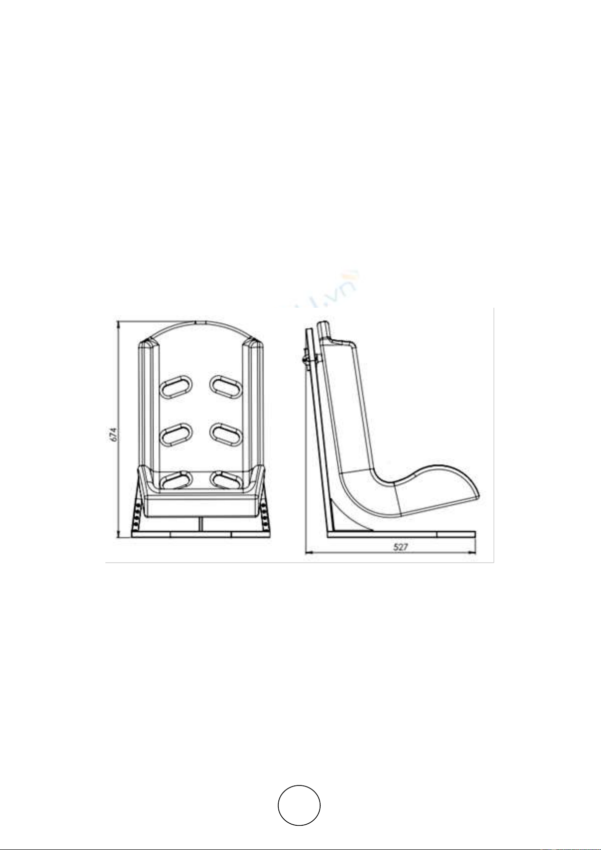
A 2D drawing with dimensions of an experimental prototype of a pendulum type child travel
seat is shown in Fig. 1.
Figure 1 2D drawing of an experimental prototype of tilting child seat
As shown in the figure above, the seat in concert with the child can rotate around
cylindrical joint located above its mass center. The seat is mounted by ball bearing on light
metal frame. It is designed as an experimental prototype. If the tests prove that the seat is
efficient and safe and if it enters in serial production, the frame can be made of polymer or
carbon. The seat used in the prototype is made of polymer. The seat was taken from an
existing non-tilting child seat model.
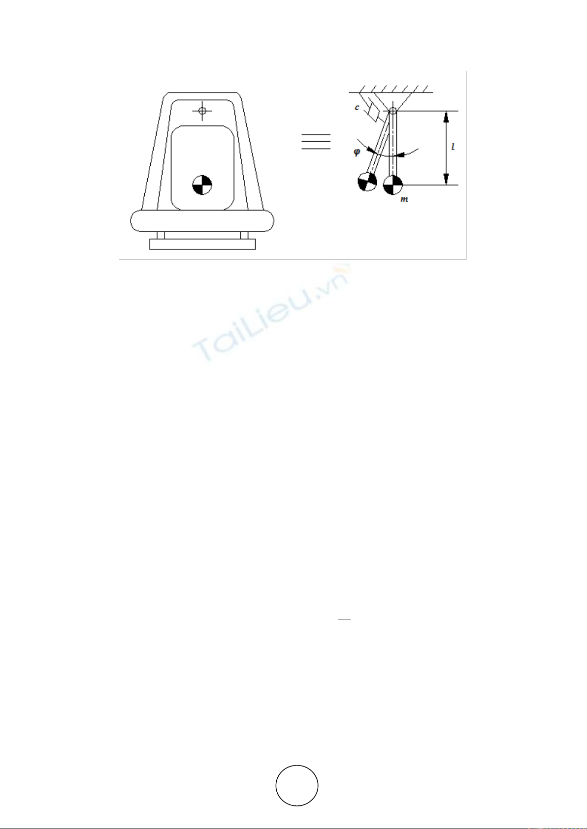
3. PENDULUM TYPE MODEL OF A CHILD TRAVEL SEAT
The described tilting seat can be presented like a physical pendulum as shown in Fig. 3. The
pendulum can rotate about a cylindrical joint. An angular damper with damping coefficient c
is placed to reduce the additional high frequency oscillation.
Numerical Simulation of Free and Forced Oscillations for Pendulum Type Child Travel Seat
http://www.iaeme.com/IJMET/index.asp 174 editor@iaeme.com
Figure 2 Equivalent pendulum type model of a tilting seat
The differential equation of the pendulum free motion is:
cmglJx sin
(1)
where
x
J
is an axle moment of inertia, about an axis of rotation passing beyond the body’s
center of mass (non-central moment of inertia) [5]:
2
mlJJ cx
(2)
where
l
is the distance between the axis crossing the center of mass and the axis of rotation
(Steiner’s theorem);
c
J
- moment of inertia about axis crossing the centre of mass;
m - mass of the child-tilting seat system;
c - angular damping coefficient;
g - gravitational acceleration.
The differential equation of the pendulum forced motion is:
McmglJx
sin
(3)
where M is the disturbance moment:
lFM c
(4)
R
v
mFc
2
(5)
where
c
F
is the centrifugal force;
v
- vehicle speed;
R
- curve radius.
N. L. Pavlov, E. E. Sokolov, M. H. Peychev and D. I. Dacova
http://www.iaeme.com/IJMET/index.asp 175 editor@iaeme.com
4. NUMERICAL SIMULATIONS
The simulations were performed using MATLAB with the parameters given in Table 1:
Table 1 Simulation parameters
Parameter
Symbol
Value
Unit
Mass of the child-tilting child seat
system
m
10
kg
Distance
l
0,28
m
Moment of inertia about axis
crossing the centre of mass
Jc
2,5
kg.m2
Angular damping coefficient
c
var.*
N.s/rad
* - the angular damping coefficient can vary for simulations performed for tuning the system.
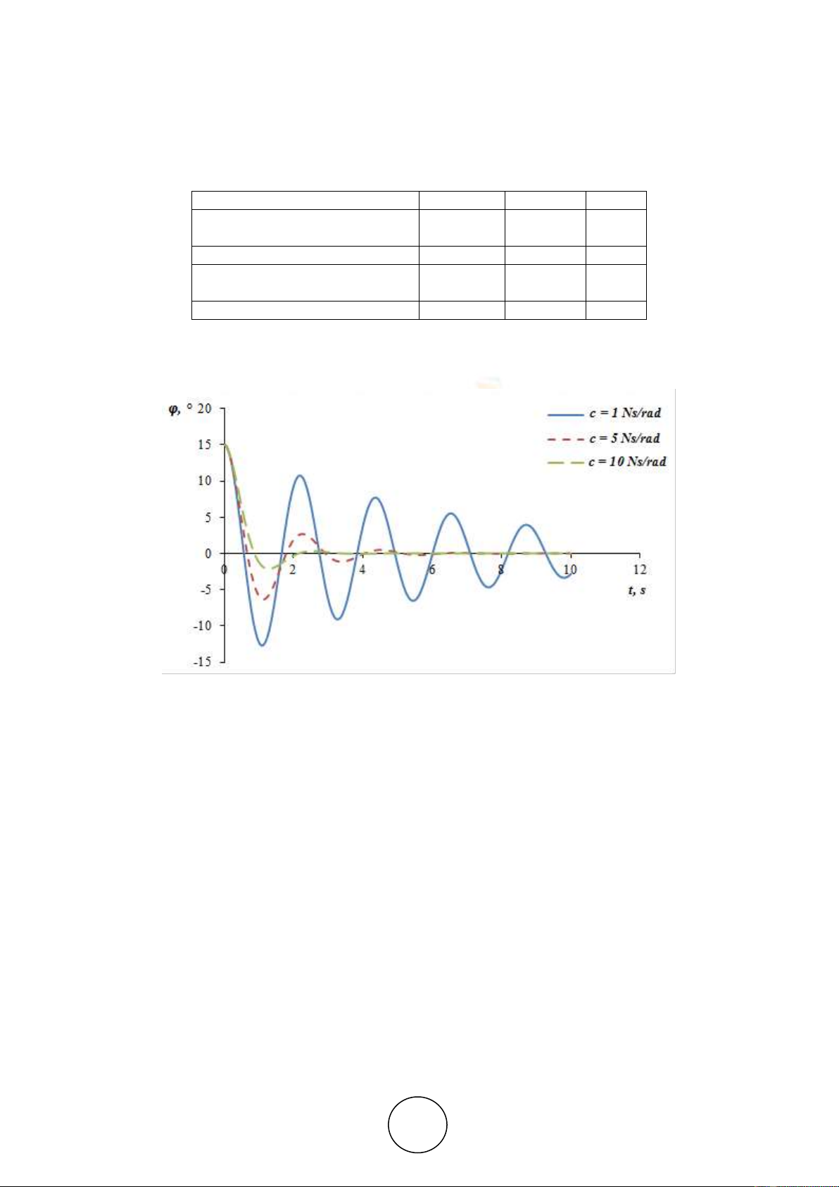
The results of free oscillations simulations with three different angular damping
coefficients are shown in Fig 3.
Figure 3 Free damped oscillations of the pendulum with different damping coefficients
The results show that if a small angular coefficient of 1 N.s/m is used the free oscillations
are damped very slowly. If the coefficient c =10 N.s/m, the motion is aperiodic with fast
damping (over-damping). Between them is situated the oscillation curve of damping with
coefficient c =5 N.s/m.
The forced oscillations simulations are performed with sinusoidal variation of the
centrifugal force. This corresponds to the slalom motion of the vehicle. It is given by the
following formula:
)sin(
max tFF cc
(6)
where
404.10
max yc maF
N;
1
rad/s
16,0
Hz is the frequency used in the simulations;
4
y
a
m/s2 is the lateral acceleration, taken from real slalom tests performed by the author
and his science team and presented in the cited papers [6, 7]. The results are obtained by
microelectromechanical inertial system (MEMS) consisting of sensors widely used in various
fields of science and engineering in the recent years [8, 9].
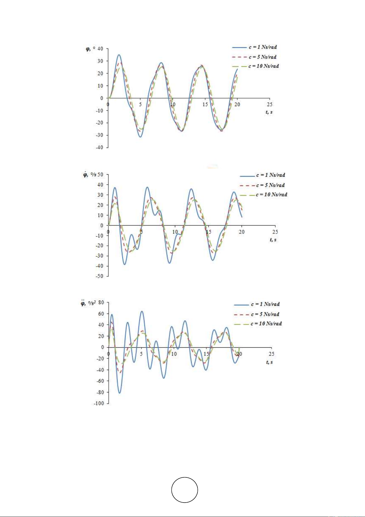
The graphical results of forced oscillations simulations with the three different angular
damping coefficients are shown in Fig. 4, 5 and 6.
Numerical Simulation of Free and Forced Oscillations for Pendulum Type Child Travel Seat
http://www.iaeme.com/IJMET/index.asp 176 editor@iaeme.com
Figure 4 Angular displacement of pendulum forced oscillations with different damping coefficients
Figure 5 Angular velocity of pendulum forced oscillations with different damping coefficients
Figure 6 Angular acceleration of pendulum forced oscillations with different damping coefficients
As can be seen in the last three figures above the angular displacement
, the angular
velocity
and the angular acceleration
have the smallest values in case of the bigger
damping coefficient
c
. In the case of the lowest damping, additional harmonics of the speed
and acceleration curves are noticed. They can reduce the efficiency of the system. As a result


![Bài tập tối ưu trong gia công cắt gọt [kèm lời giải chi tiết]](https://cdn.tailieu.vn/images/document/thumbnail/2025/20251129/dinhd8055/135x160/26351764558606.jpg)