
PIC Tutorial Hardware
The hardware required consists of a number of small boards (built on Veroboard), which
connect together via ten pin leads using Molex connectors. The first board (Main Board) carries
the PIC16F628 processor and 5V regulator - the board can be fed from a simple 9V battery.
Some of the later tutorials will require two processor boards, this is the reason for the second
connector on PortB - the two processors will communicate with each other over a standard 9600
baud serial bus, the second board can be either powered from the first (using a four wire
connection lead), or powered from it's own supply (using a three wire connection lead). The lead
consists of a ground wire, RB1 to RB2, RB2 to RB1, and an optional 5V wire. RB1 and RB2
cross over so we can experiment with the built-in hardware USART as well as software serial
communications.
I've added a second processor board, based on the PIC16F876, this adds a third port, and
includes 5 channels of 10 bit analogue input - the existing tutorials based on the PIC16F628
should work with a few slight changes, these are explained on the changes page, as I'm running
the 16F876 at 20MHz (5 times faster than the 16F628) the delay routines will need altering as
well.
The second board (LED Board) carries eight LED's with associated series resistors, and is
used in the first series of tutorials. The third board (Switch Board) provides a row of four
switches, and four LED's (so you can do some exercises without needing the previous LED
board). The fourth board (LCD Board) only has a variable resistor (contrast) and a single resistor
(pull-up for RA4), the actual LCD module is mounted off board and connected via another 10
way Molex connector, this allows you to plug different LCD's in. The fifth board (Joystick
Board) provides an interface for a standard PC analogue joystick, giving access to the two
analogue controls and the two buttons. The sixth board (IR Board) has an Infrared transmitter
and receiver, using two of them with two processor boards we can experiment with Infrared
communication. The seventh board (I2C EEPROM Board) uses a standard EEPROM 24Cxx
series (I used a 24C04 and a 24C256). With I2C there are a great many components you can
connect to the bus, the basic software interface remains pretty well the same, except that some
chips (like the 24C256) use an extended addressing mode to access more memory, the standard
addressing mode can only access 2kB (8 x 256 byte pages). I'll be adding some other I2C based
boards later, they will use the same basic I2C routines as the existing I2C EEPROM board does.
The eighth board (I2C Clock Board) implements a battery backed clock, using a PCF8583P
chip, and the ninth one (I2C A2D Board) introduces analogue to digital conversion, using a
PCF8591P chip. The tenth board (I2C Switch Board) is very simple, it provides four push button
switches for use with the other I2C boards. The eleventh board is the PIC16F876 processor
board, and the twelfth is an RS232 interface board using the standard MAX232 chip.
The various boards.
Main Board The main 16F628 processor board (two required later).
Main Board Two A 16F876 based processor board.
LED Board Eight LED's for displaying the outputs from one port.
Switch Board Four pushbutton switches for connecting to one port.
LCD Board An LCD text display board, in 4 bit mode, connecting to one port.
Joystick Board A board for connecting an analogue PC joystick.
IR Board An Infrared transmitter/receiver board (two required).
I2C EEPROM Board An I2C EEPROM board.
I2C Clock Board An I2C battery backed clock board.
I2C A2D Board A four channel A2D converter via the I2C bus.
I2C Switch Board Four push buttons for use with the I2C boards.
RS232 Board An RS232 interface board.
Next Board To be arranged!.
I obtained the Molex connector parts from RS Components, for the PCB part there are two
options, the first has fully open pins, the second has plastic locking guides at the back, which
means you can't get it on the wrong way round or out of step - use which ever you prefer, I
initially used the open ones, but used locking ones on my second processor board and the IR
Board. You can buy an expensive crimping tool for fitting the Socket Terminals to the wire, but
I simply soldered them in place - it's a little fiddly, but reasonably easy - once the terminals are
fitted on the wire they are easily pushed into place in the socket housing. I used a blue wire to
mark pin one, and the rest were all white. I made a number of leads up, about 12cm long, with
connectors at both ends, and a single ended one which solders to the LCD module. A special
longer one, with only 4 wires (two of them crossed over) was made for cross connecting the two
processor boards.
Connector parts used.
Part Description RS Part Number Quantity
PCB Header (non-locking) 467-582 1 Pack (10)
PCB Header (locking) 453-230 1 Pack (10)
Socket Housing 467-633 1 Pack (10)
Socket Terminals 467-598 1 Pack (100)
PIC Tutorial Main Board
Main Board
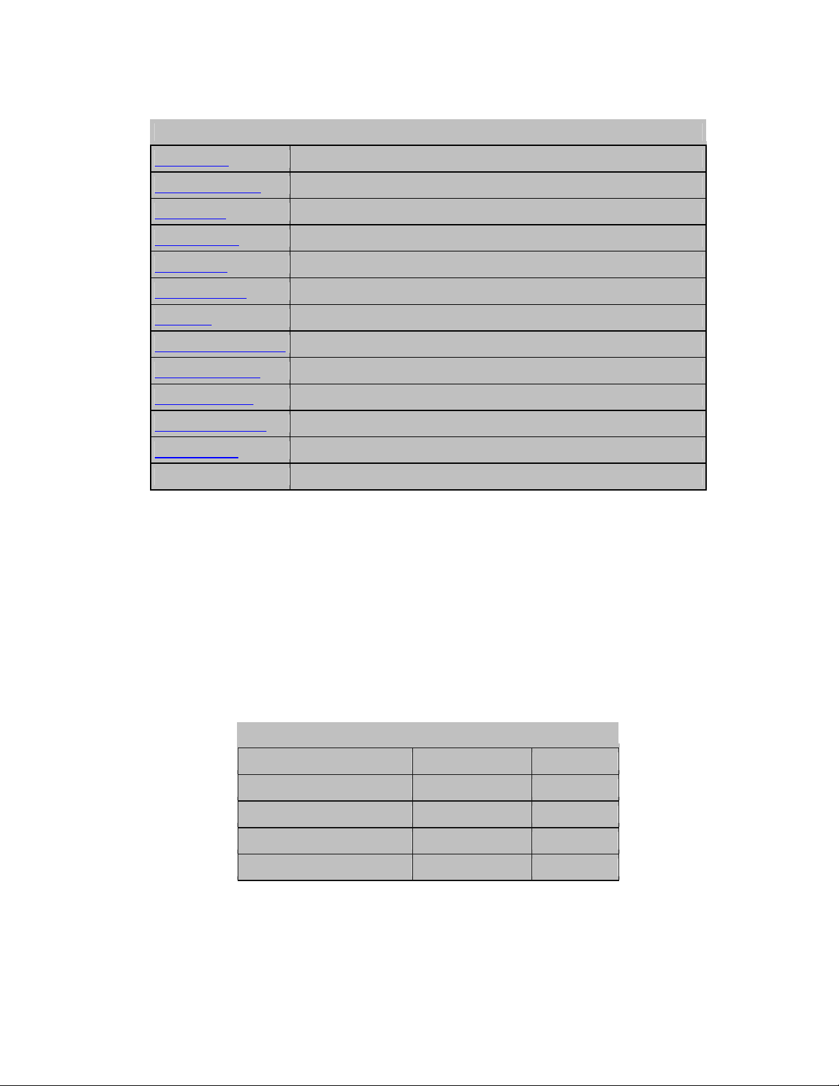
This is the circuit of the main board for the tutorials, it consists of the PIC16F628, a 7805
regulator, 3 capacitors, three ten pin connectors, one for PortA, and two for PortB (the second
for connecting two of these boards together), and a two pin ground test connection - optionally it
also includes an LED, a resistor, and two 2 pin jumpers. Each of the three ten pin connectors is
wired identically, with a ground connection at the left side, and a 5V connection at the right -
this will allow you to plug the same extension board into either port, and help to demonstrate
their differences. The capacitors C1 and C2 are to keep the 7805 stable, they have a tendency to
oscillate without them, and C3 is just a decoupling capacitor placed near the chip, always a good
practice (although PIC's do seem very tolerant of them). The jumpers J1 and J2 allow the LED
to be connected either to 5V (J2) as a 'power on' indicator, or to RB7 (J1) where it can be
switched by the port pin - this allows you to do something before you build any further boards.
Under no circumstances connect both J1 and J2 at the same time, it's likely to damage the
chip.
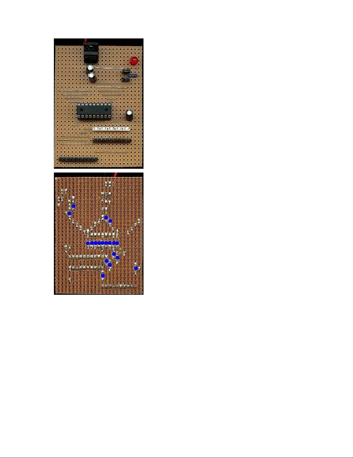
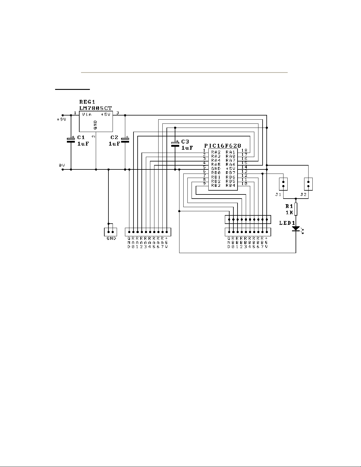
This is a photo of the main board, it's built on a piece of
Veroboard 23 strips wide,
b
y 31 holes high. The left of the
two black connectors at the bottom is PortA, the right pair are
PortB. All the wire jumpers are required to line the
connectors up neatly. In order to prevent the pins of the PIC
getting damaged, the PIC is permanently inserted in a 'turned
pin' socket, this is then plugged into a normal socket on the
b
oard. To program it the PIC, complete with turned pin
socket, is unplugged and inserted in the programmer,
programmed and then returned. This is very easy to do, and
the 'turned pin' socket prevents any damage. The PIC is
capable of being programmed in-circuit, but it adds circuit
complications and uses up I/O pins, so I haven't implemented
that. J1 is the upper of the two jumpers, nearest the LED.
Although it's not very easy to see in this picture, pin one of
the PIC is to the left. The 2 pin ground test connection isn't
fitted in this picture, it fits vertically just above C3, on the
ground rail connecting to the negative end of C3.
This is a bottom view of the board, I've indicated the track
cuts (19 of them) with blue circles, with this picture, and the
one above, it should be fairly easy to duplicate the board -
remember - there are 19 track cuts, and 21 wire links.
PIC Tutorial Main Board Two
Main Board Two
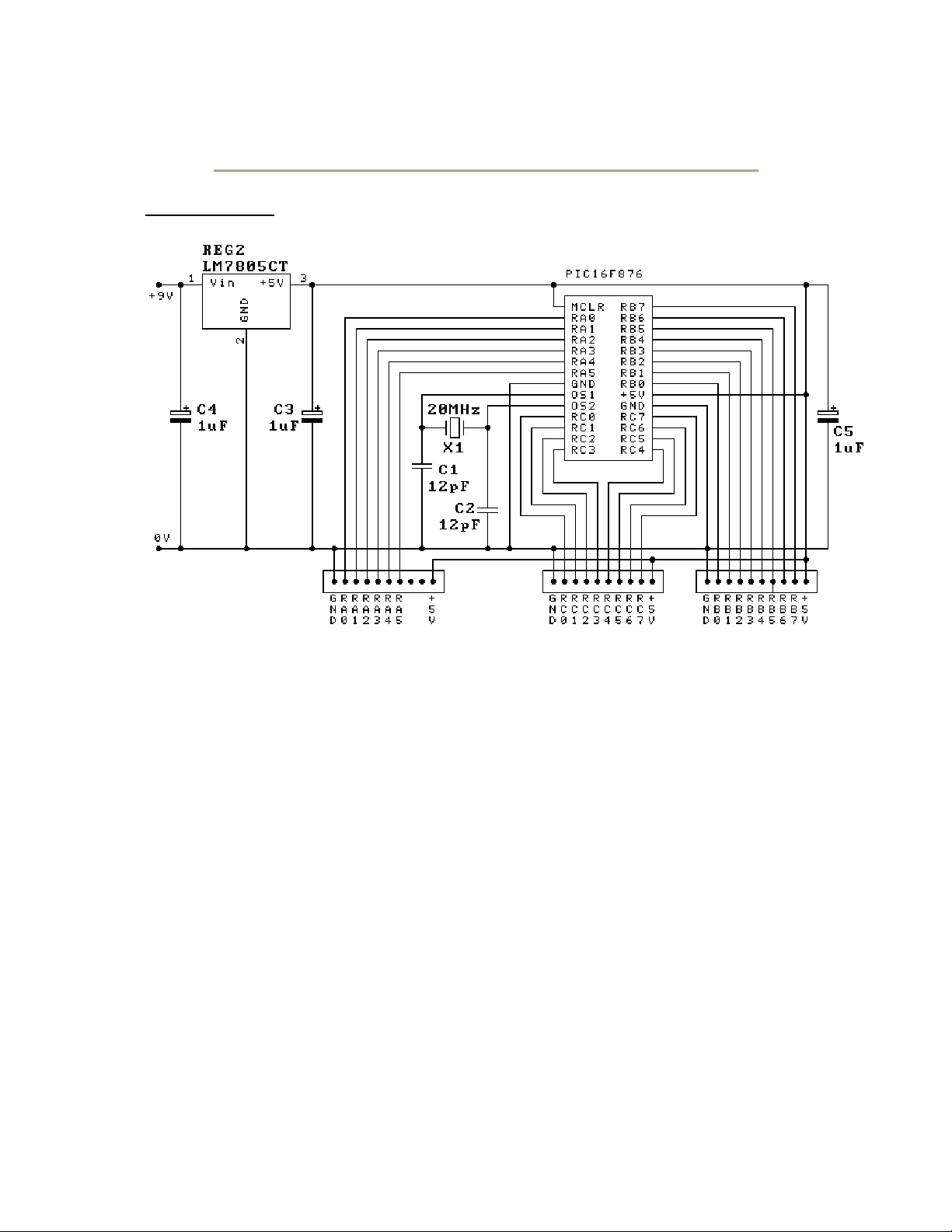
This is the circuit of the second main board for the tutorials, it consists of the PIC16F876, a
7805 regulator, a 20MHz crystal, 5 capacitors, three ten pin connectors, one for PortA, one for
PortB, and one for PortC . Each of the three ten pin connectors is wired identically, with a
ground connection at the left side, and a 5V connection at the right - this will allow you to plug
the same extension board into any port, and help to demonstrate their differences - the most
obvious difference is that PortA only has 6 I/O lines, which can be either digital I/O or analogue
inputs, with 10 bit resolution.
Basically it's very similar to the 16F628 tutorial board, but has an extra port and added
facilities - as the 16F876 doesn't have an internal oscillator a crystal is required for the clock
oscillator - I choose a 20MHz crystal for this, if you can't get a 20MHz chip the 4MHz 16F876's
seem perfectly happy to run at 20MHz - I suspect they are exactly the same chip, and graded to
provide the two different versions.
![Tài liệu học tập Vi điều khiển ứng dụng trong đo lường và điều khiển [mới nhất]](https://cdn.tailieu.vn/images/document/thumbnail/2021/20210705/lovebychance06/135x160/7771625534375.jpg)


%20--%3e%3cdefs%3e%3cstyle%3e%20.st0%20{%20fill:%20%23fff;%20}%20.st1%20{%20fill:%20%237800fa;%20}%20%3c/style%3e%3c/defs%3e%3cpath%20class='st1'%20d='M117.78,12.18H43.11c2.9,3.47,4.65,7.94,4.65,12.82,0,5.6-2.3,10.66-6.01,14.29h76.02l7.22-13.56-7.22-13.56Z'/%3e%3cg%3e%3cpath%20class='st0'%20d='M53.58,26.17h-.59v-1.46h.59v-4.96h2.83c1.78,0,2.67.94,2.67,2.82v5.76c0,1.87-.89,2.81-2.67,2.81h-2.83v-4.96ZM55.36,21.37v3.34h1.1v1.46h-1.1v3.34h1.01c.61,0,.91-.37.91-1.1v-5.93c0-.74-.3-1.1-.91-1.1h-1.01Z'/%3e%3cpath%20class='st0'%20d='M65.99,31.14h-1.8l-.31-2.07h-2.19l-.31,2.07h-1.64l1.82-11.39h2.62l1.82,11.39ZM65.28,18.04c-.25.46-.51.77-.75.94-.21.15-.47.22-.79.22-.26,0-.57-.07-.92-.22l-.38-.15c-.14-.05-.26-.07-.37-.07-.3,0-.53.18-.71.54l-.91-.68c.25-.46.51-.77.75-.94.21-.14.48-.21.79-.21.26,0,.57.07.92.21l.38.15c.14.05.26.07.37.07.3,0,.53-.18.71-.54l.91.68ZM61.91,27.52h1.73l-.87-5.76-.87,5.76Z'/%3e%3cpath%20class='st0'%20d='M74.53,26.89v1.52c0,1.91-.89,2.86-2.67,2.86s-2.67-.95-2.67-2.86v-5.93c0-1.91.89-2.86,2.67-2.86s2.67.95,2.67,2.86v1.11h-1.69v-1.22c0-.75-.31-1.12-.93-1.12s-.93.37-.93,1.12v6.15c0,.74.31,1.11.93,1.11s.93-.37.93-1.11v-1.63h1.69Z'/%3e%3cpath%20class='st0'%20d='M81.4,31.14h-1.8l-.31-2.07h-2.19l-.31,2.07h-1.64l1.82-11.39h2.62l1.82,11.39ZM75.9,19.2l1.52-1.91h1.71l1.51,1.91h-1.61l-.76-.95-.75.95h-1.61ZM77.32,27.52h1.73l-.87-5.76-.87,5.76ZM83.1,15.99l-1.76,1.91h-1.26l1.17-1.91h1.86Z'/%3e%3cpath%20class='st0'%20d='M84.86,19.75c1.78,0,2.67.94,2.67,2.82v1.48c0,1.87-.89,2.81-2.67,2.81h-.85v4.28h-1.79v-11.39h2.64ZM84.01,21.37v3.86h.85c.58,0,.87-.36.87-1.08v-1.71c0-.71-.29-1.07-.87-1.07h-.85Z'/%3e%3cpath%20class='st0'%20d='M93.51,19.75c1.78,0,2.67.94,2.67,2.82v1.48c0,1.87-.89,2.81-2.67,2.81h-.85v4.28h-1.79v-11.39h2.64ZM92.66,21.37v3.86h.85c.58,0,.87-.36.87-1.08v-1.71c0-.71-.29-1.07-.87-1.07h-.85Z'/%3e%3cpath%20class='st0'%20d='M98.8,31.14h-1.79v-11.39h1.79v4.88h2.03v-4.88h1.83v11.39h-1.83v-4.88h-2.03v4.88Z'/%3e%3cpath%20class='st0'%20d='M105.36,24.55h2.46v1.62h-2.46v3.34h3.09v1.63h-4.88v-11.39h4.88v1.63h-3.09v3.18ZM108.17,17.29l-1.76,1.91h-1.26l1.17-1.91h1.86Z'/%3e%3cpath%20class='st0'%20d='M112.2,19.75c1.78,0,2.67.94,2.67,2.82v1.48c0,1.87-.89,2.81-2.67,2.81h-.85v4.28h-1.79v-11.39h2.64ZM111.35,21.37v3.86h.85c.58,0,.87-.36.87-1.08v-1.71c0-.71-.29-1.07-.87-1.07h-.85Z'/%3e%3c/g%3e%3ccircle%20class='st1'%20cx='25'%20cy='25'%20r='20'/%3e%3cpath%20class='st0'%20d='M32.78,19.27c2.92,0,4.43,2.55,5.28,5.33l.71,2.17c.14.38-.33.75-.71.75h-5.61c.19-.33.24-.71.09-1.08l-.75-2.45c-.43-1.32-.99-2.64-1.79-3.77.75-.57,1.65-.94,2.78-.94h0ZM25,18.38c3.25,0,4.9,2.78,5.89,5.89l.76,2.45c.14.42-.33.8-.8.8h-11.69c-.42,0-.94-.38-.8-.8l.75-2.45c.99-3.11,2.64-5.89,5.89-5.89h0ZM25,11.35c1.74,0,3.11,1.37,3.11,3.11s-1.37,3.11-3.11,3.11-3.11-1.41-3.11-3.11,1.41-3.11,3.11-3.11h0ZM17.27,19.27c1.08,0,1.98.38,2.73.94-.8,1.13-1.37,2.45-1.74,3.77l-.8,2.45c-.14.38-.05.75.09,1.08h-5.56c-.42,0-.9-.38-.75-.75l.71-2.17c.9-2.78,2.41-5.33,5.33-5.33h0ZM17.27,12.91c1.51,0,2.78,1.27,2.78,2.83s-1.27,2.83-2.78,2.83-2.83-1.27-2.83-2.83,1.27-2.83,2.83-2.83h0ZM32.78,12.91c1.56,0,2.78,1.27,2.78,2.83s-1.23,2.83-2.78,2.83-2.83-1.27-2.83-2.83,1.27-2.83,2.83-2.83h0ZM27.07,28.56v.09c0,.57-.24,1.08-.61,1.46h0v.05c-.38.33-.9.57-1.46.57s-1.08-.24-1.46-.61h0c-.38-.38-.61-.9-.61-1.46v-.09h1.41v.09c0,.19.05.38.19.47v.05c.09.09.28.19.47.19s.38-.09.47-.19v-.05c.14-.09.24-.28.24-.47t-.05-.09h1.41ZM30.99,28.56v.09c0,1.65-.66,3.16-1.74,4.24-1.08,1.08-2.59,1.79-4.24,1.79s-3.16-.71-4.24-1.79l-.05-.05c-1.04-1.08-1.7-2.55-1.7-4.2v-.09h1.41v.09c0,1.27.47,2.4,1.27,3.25h.05c.85.85,1.98,1.37,3.25,1.37s2.4-.52,3.25-1.37c.85-.8,1.37-1.98,1.37-3.25v-.09h1.37ZM34.99,28.56v.09c0,2.78-1.13,5.28-2.92,7.07-1.79,1.79-4.29,2.92-7.07,2.92s-5.23-1.13-7.07-2.92c-1.79-1.79-2.92-4.29-2.92-7.07v-.09h1.41v.09c0,2.4.94,4.53,2.5,6.08,1.56,1.56,3.72,2.5,6.08,2.5s4.52-.94,6.08-2.5c1.56-1.56,2.5-3.68,2.5-6.08v-.09h1.41Z'/%3e%3c/svg%3e)