
* Corresponding author. Tel.: +989122414371; Fax: +982412283204
E-mail addresses: omid.rahmani@znu.ac.ir (Omid Rahmani)
© 2013 Growing Science Ltd. All rights reserved.
doi: 10.5267/j.esm.2014.1.004
Engineering Solid Mechanics 2 (2014) 119-130
Contents lists available at GrowingScience
Engineering Solid Mechanics
homepage: www.GrowingScience.com/esm
Vibrational response of functionally graded circular plate integrated with
piezoelectric layers: An exact solution
A. A. Jandaghiana, A. A. Jafarib and O. Rahmania*
aSmart Structures and New Advanced Materials Laboratory, Mechanical Engineering Department, University of Zanjan, Zanjan, Iran
bFaculty of Mechanical Engineering, K. N. Toosi University of Technology, Tehran. Iran
A R T I C L E I N F O A B S T R A C T
Article history:
Received September 20, 2013
Received in Revised form
October, 14, 2013
Accepted 30 January 2014
Available online
31 January 2014
In this paper, harmonic forced vibration of circular functionally graded plate integrated with
two uniformly distributed actuator faces made of piezoelectric material is studied. The material
properties of the functionally graded substrate layers are assumed to be graded in the thickness
direction according to the power-law distribution, also the distribution of electric potential field
along the thickness direction of piezoelectric layers is modeled by a quadratic function. The
governing equations are solved for simply supported boundary condition of the sandwich
circular plate and the solutions are presented by elementary Bessel functions. The performance
of the present model is compared with that of finite element analyses as well as other available
literature by the presentation of comparative results obtained for several examples
encompassing different power indexes and vibration modes. The results show that thickness of
piezoelectric layer and changing the power index in FG material has a significant influence on
the deflection and natural frequencies of system.
© 201
4
Growing Science Ltd. All rights reserved.
Keywords:
Functionally graded material
Piezoelectric
Circular plate
Classical plate theory
Forced vibration
1. Introduction
The well-regulated vibrational properties of piezoelectric materials are broadly known as one of
the most significant resources for the improvement in the smart structures. Intelligent self-monitoring
and self-adaptive structures, incorporating piezoelectric patches, are now extensively used in the
active and passive vibration control, in micro-electromechanical systems, in medical apparatus and in
measuring devices. A metal substrate surface embedded or bonded by a piezoelectric sheet has
received significant attention during last years for applied designs of actuators and sensors due to the
electromechanically coupling characteristics.

120
In recent times, functionally graded (FG) materials which exhibit smooth variation of material
properties have been studied for developing intelligent functionally graded structures. By employing
piezoelectric materials as sensors or actuators, intelligent FG structures have been made with
proficiencies of self-monitoring and self-controlling. The design of systems including active
piezoelectric materials requires comprehensive modeling of the mechanical, electrical and coupling
properties of the piezoelectric elements, the host structure and their interactions. In the following
recent progresses and findings in modeling of smart FG structures will be discussed.
Batra and coworkers (Batra & Liang 1997; Vel & Batra 2001) studied the vibration problem of a
rectangular laminated plate with embedded piezoelectric actuators and sensors subjected to transient
thermal loading. Batra and Geng (2002) considered a FG viscoelastic layer with a homogeneous PZT
constraining layer and carried out the 3D transient analysis of the structure with the finite element
method. He et al. (2001) proposed a FE formulation based on the classical laminated plate theory
(CLPT) for the vibration and shape control of the FG material plates with integrated piezoelectric
actuators and sensors and used a feedback control algorithm for the active control of the dynamic
response of the plate through closed loop control. A FE formulation was proposed by Liew et al.
(2002) for modeling and control of piezoelectric shell laminates under coupled temperature,
displacement and electric potential fields. The base shell has been made of FG material which
consists of combined metal– ceramic materials with different mixing ratios. Ootao and Tanigawa
(2000) and Tanigawa (2001) investigated the FG simply supported plate integrated. A study on the
nonlinear vibration and dynamic response of a FG material plate with surface-bonded piezoelectric
layers in thermal environments was developed by Huang and Shen (2006). The nonlinear
formulations were based on the higher-order shear deformation plate theory (HSDT) including
thermo-piezoelectric effects. In this study, they accounted to heat conduction and temperature-
dependent material properties, and it was assumed a variation through the plate thickness both for the
temperature field and for the electrical field intensity.
A study on FG beams with surface integrated piezoelectric actuators and sensors based on a state
space formulation was carried out by Bian et al. (2006). In their study, the bonding adhesive between
the host beam and the piezoelectric layers was modeled by a spring layer in order to consider its
effect. The bonding conditions were simulated through the consideration of different spring layer
parameters. Free axisymmetric vibration problem of piezoelectric coupled thin circular and thin
annular FGM plates has been carried out by Ebrahimi and Rastgoo (2008 a,b). Also Ebrahimi et al.
(2009) suggested an analytical solution to analysis of smart moderately thick shear deformable and
circular FG plate based on the Mindlin’s plate theory. Wang and Quek (2001) studied free vibration
of a circular plate surface bonded by two piezoelectric layers, based on the Kirchhoff theory. They
have shown the mode shape of the electric potential obtained from free vibration analysis is generally
to be non-uniform in the radial direction in contrast to what is commonly assumed. A study on the
performance of vertically reinforced 1–3 piezoelectric composite distributed actuator in the active
constrained layer damping system bonded to a FG plate was carried out by Ray and Batra (2007).
They modelled the deformations of each layer by the first-order shear deformation theory.
Jandaghian et al. (2013) suggested an analytical solution to investigate the transient motion of a
circular plate surface bonded by two piezoelectric layers. By applying high-order sandwich panel
theory (HSAPT) Rahmani et al. (2009) studied the free vibration of sandwich structure with a
flexible functionally graded syntactic core. Yapeng (2003) presented an exact analysis of the free
vibration of a functionally gradient piezoelectric plate. The solution of the derived governing
differential equations was obtained through the power series expansion method. The natural
frequencies and the modal distributions of free vibration of a functionally gradient piezoelectric plate
were investigated.
In another study, Kargarnovin et al. (2007) investigated the active vibration control of FG
material plates using piezoelectric sensor/actuator patches, using classical laminated plate (CLP)

A. A. Jandaghian et al. / Engineering Solid Mechanics 2 (2014)
121
theory. In their work the effect of the feedback gain and the volume fraction on the plate frequency
and displacement was studied. Es’haghi et al. (2011) presented an analytical solution for vibration
study of piezoelectric coupled FG Mindlin plates those have open circuit piezoelectric patches and
have been used as sensors. Fakhari et al. (2011) suggested a FE formulation based on HSDT plate
theory to investigate the nonlinear natural frequencies, time and frequency responses of FG plate with
surface-bonded piezoelectric layers under thermal, electrical and mechanical loads. Numerical results
have been presented to study the effects of the volume fraction exponent, the applied voltage in
piezoelectric layers, the thermal load and the vibration amplitude on nonlinear natural frequencies
and time response of the plate with integrated piezoelectric layers was studied.
Hashemi et al. (2012) developed an analytical solution for the free vibration of piezoelectric
coupled FG thick circular/annular plates on the basis of the Mindlin’s FSDT theory and studied the
effects of coupling between in-plane and transverse displacements on the frequency parameters. Loja
et al. (2012) studied the static and free vibration behavior of functionally graded sandwich plate type
structures, using B-spline finite strip element models based on different shear deformation theories.
Geometrical nonlinear static and free vibration analyses of FG piezoelectric plates using FEM were
studied by Behjat and Khoshravan (2012). On their work different sets of mechanical and electrical
loadings were considered. The plate with FG piezoelectric material was considered to vary gradually
through the thickness by a power law distribution. The electric potential was assumed to vary in a
quadratic way through the thickness and was considered to be a nodal degree of freedom.
Liew et al (2003) presented a FE model for the static and dynamic piezothermoelastic analysis
and control of FGM plates under temperature gradient environments using integrated piezoelectric
sensor/actuator layers. They also applied a feedback control algorithm that couples the direct and
inverse piezoelectric effects to provide active control of the integrated FGM plate in a closed loop
system.
Along with the carried out literature review and to the best knowledge of authors there is no
references for the forced vibration of FG circular plate integrated with piezoelectric material. In this
study, the forced harmonic vibration of a FG thin circular plate integrated with piezoelectric layers is
investigated for different boundary conditions. Both top and bottom layers of each piezoelectric layer
are fully covered by electrodes which are shortly connected. The thickness of electrodes is considered
to be extremely small compared to the plate thickness. Thus, in the following formulation, the
mechanical effects of the electrodes are neglected. The properties of the substrate layers were graded
in the thickness direction according to a volume fraction power law distribution. The distribution of
electric potential field in the thickness direction of the piezoelectric layers is simulated by a quadratic
function and the solutions are presented in terms of a single, elementary Bessel function. A consistent
formulation based on the classical plate theory (CPT) that satisfies the Maxwell static electricity
equation is presented for piezoelectric layers. The results are validated by those obtained from FEA
and other available literature.
2. Modeling of functionally graded properties
The properties of the circular plate are considered to vary through the thickness of the plate with
a power-law distribution of the volume fractions of the two materials in between the two surfaces. In
fact, the top surface (z = h) of the plate is ceramic-rich whereas the bottom surface (z = -h) is metal-
rich. Poisson’s ratio ν is assumed to be constant throughout the analysis. Young’s modulus and mass
density are assumed to vary continuously through the plate thickness as
( ) ( ) ( )
c m f m
E z E E V z E
, (1)
( ) ( ) ( )
c m f m
z V z
, (2)
122
where the subscripts m and c represent the metallic and ceramic constituents, respectively, E and ρ
are modulus of elasticity and density, respectively and the volume fraction V
f
may be given by
, 0,
2
g
f
z h
V g
h
(3)
where g is the power law index and takes only positive values. For g = 0 and g =1, the plate is fully
ceramic and metallic, respectively; whereas the composition of metal and ceramic is linear for g = 1.
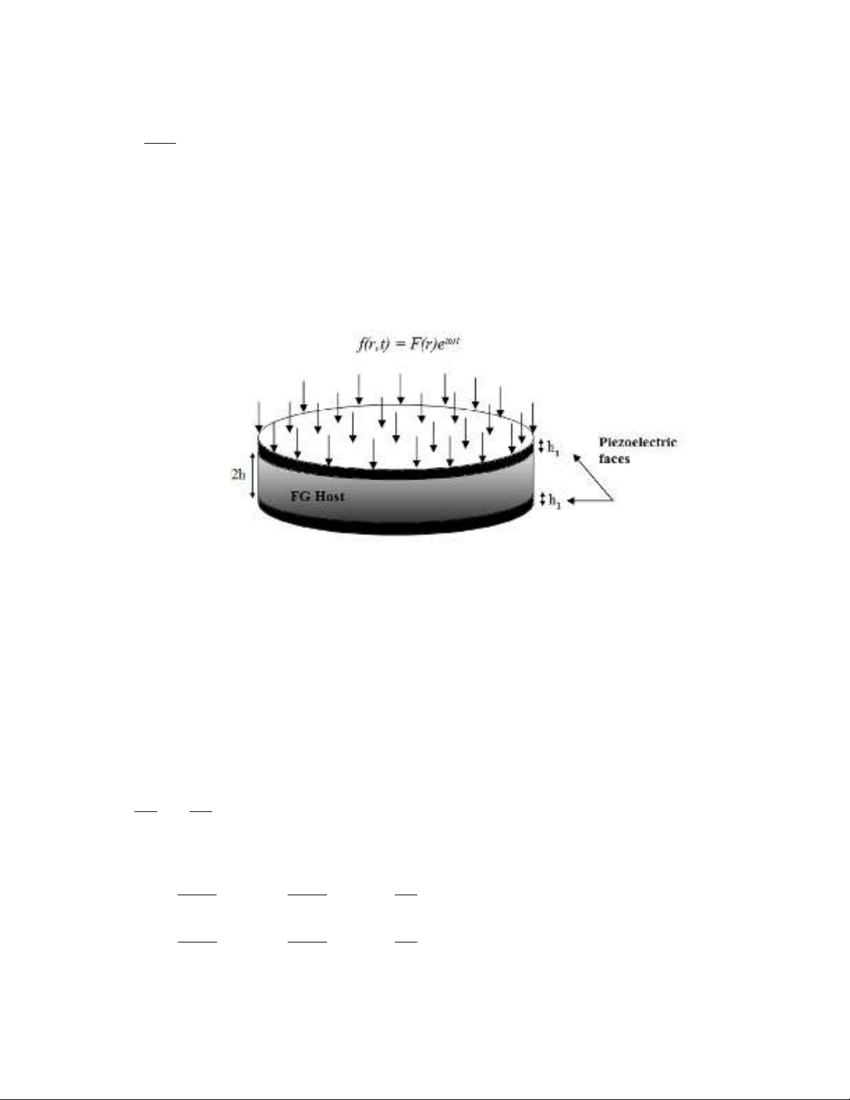
3. Basic equations of FG sandwich circular plate with piezoelectric layers
Consider a flat, thin FG sandwich circular plate, including one host layer in the middle and two
identical piezoelectric faces bonded perfectly to the upper and lower surfaces of the host layer, with
host plate thickness 2h and piezoelectric layer thickness h
1
, radius r, as illustrated in Fig. 1.
Fig. 1. Cross section of FGM circular plate with two piezoelectric layers mounted on its upper and
lower surfaces
The constitutive equations for an piezoelectric layer in reference coordinate system (z,r,θ) are
(Tiersten, 1969):
zz
EE
r
Ep
r
EeCCC
31131211
, (4)
zz
EE
r
Ep
EeCCC
31131112
, (5)
zz
EE
r
Ep
z
EeCCC
33331313
, (6)
and ε
z
for plane stress is obtained from Eq. (6)
33 13
33 33
( )
z z r
e C
E
C C
. (7)
Substituting Eq. (7) into Eq. (4) and Eq. (5) gives
2 2
13 13 13
11 12 31 33
33 33 33
( ) ( )
[ ] [ ] [ ]
E E
p E E
r r z
E E
C C C
C C e e E
C C C
(8)
2 2
13 13 13
12 11 31 33
33 33 33
( ) ( )
[ ] [ ] [ ]
E E
p E E
r z
E E
C C C
C C e e E
C C C
(9)

A. A. Jandaghian et al. / Engineering Solid Mechanics 2 (2014)
123
E
C11 and E
C12 are the elastic modulus of the piezoelectric material in the radial and tangential
directions, measured at constant electric field; and e31 is the piezoelectric constant of the piezoelectric
layer.
The stress components in the FG plate are expressed as (Timoshenko et al., 1959)
,
,
2
( )
1
r
f
r rr
w
zE z w
r
, (10)
,
,
2
( )
1
r
f
rr
w
zE z
w
r
, (11)
0
r. (12)
When the two major surfaces of the piezoelectric layer are held at zero voltage (i.e., closed circuit or
boundary conditions), in this study we decided to adopt the following electric potential function
which is appropriate for the proposed system (Wang et al., 2001):
2
1
1
1
2
1
1
1
2 2
1 ( , ),
( , , )
2 2
1 ( , ), -
z h h
r t h z h h
h
r z t
z h h
r t h h z h
h
(13)
where, z is measured from the mid-plane of the plate in the global z-direction, h1 is the thickness of
the piezoelectric layer, and φ(r,t) is the electric potential on the mid-surface of the piezoelectric layer.
For boundary condition the electrodes on each piezoelectric layer are short-circuit and also, zero
electrical potential at r = a is obtained by connecting piezoelectric layers to ground. It is seen from
Eq. (13) that the electric boundary condition of the short-circuit ( 0
) at the internal surfaces
hz
and the external surfaces )( 1
hhz of each piezoelectric layer is completely satisfied. The
components of electric field intensity E and electric flux density D is written as (Wang et al., 2001)
2
2
1 1 1
1 8( ) 4
1 4 , , 0
2
r z
z h z h
E E E
h r h h
(14)
2
2 2
33 1
11 31
2
1 1
8 ( / 2)
1
1 4 , , 0
2
r z
z h h
z h
D D e z w D
h r h
(15)
Er , Eθ and Ez are the electric field intensity in the r,θ and z directions, respectively; Dr , Dθ and Dz are
the corresponding electric displacement; 11
and 33
are the dielectric constants of the piezoelectric
layer; where 11
and 33
are reduced dielectric constants of the piezoelectric layer for the plane stress
problem, which are given by 1111 ,)/( 33
2
333333
E
Ce .
4. Governing equations
Afterward the resultant shear force is derived as:
,
r
r r r
M M
Q M
r
(16)


![Giáo trình Cấu trúc dữ liệu và giải thuật - Trường CĐ Cơ điện Hà Nội [Mới nhất]](https://cdn.tailieu.vn/images/document/thumbnail/2026/20260323/lionelmessi01/135x160/58171774381670.jpg)


![Giáo trình Tiện nâng cao (Nghề Cắt gọt kim loại, Trình độ Cao đẳng) - Trường Cao đẳng Cơ điện Hà Nội [Mới nhất]](https://cdn.tailieu.vn/images/document/thumbnail/2026/20260323/lionelmessi01/135x160/48101774403543.jpg)


