
4/30/2012
1
Nov 16, 2004
Voltammetry
Lecture Date: April 28th, 2008
Reading Material
●Skoog, Holler and Crouch: Ch. 25
●Cazes: Chapter 17
●For those using electroanalytical chemistry in their work,
see:
A. J. Bard and L. R. Faulkner, “Electrochemical Methods”, 2nd
Ed., Wiley, 2001.

4/30/2012
2
Voltammetry
Voltammetry techniques measure current as a
function of applied potential under conditions that
promote polarization of a working electrode
Polarography: Invented by J. Heyrovsky (Nobel
Prize 1959). Differs from voltammetry in that it
employs a dropping mercury electrode (DME) to
continuously renew the electrode surface.
Amperometry: current proportional to analyte
concentration is monitored at a fixed potential
Polarization
Some electrochemical cells have significant
currents.
– Electricity within a cell is carried by ion motion
– When small currents are involved, E = IR holds
– R depends on the nature of the solution (next slide)
When current in a cell is large, the actual potential
usually differs from that calculated at equilibrium
using the Nernst equation
– This difference arises from polarization effects
– The difference usually reduces the voltage of a galvanic
cell or increases the voltage consumed by an electrolytic
cell
4/30/2012
3
Ohmic Potential and the IR Drop
To create current in a cell, a driving voltage is
needed to overcome the resistance of ions to move
towards the anode and cathode
This force follows Ohm’s law, and is governed by
the resistance of the cell:
IREEE leftrightcell
Electrodes
IR Drop
More on Polarization
Electrodes in cells are polarized over certain
current/voltage ranges
“Ideal” polarized electrode: current does not vary
with potential
4/30/2012
4
Overvoltage and Polarization Sources
Overvoltage: the difference between the equilibrium
potential and the actual potential
Sources of polarization in cells:
– Concentration polarization: rate of transport to
electrode is insufficient to maintain current
– Charge-transfer (kinetic) polarization: magnitude
of current is limited by the rate of the electrode
reaction(s) (the rate of electron transfer between
the reactants and the electrodes)
– Other effects (e.g. adsorption/desorption)
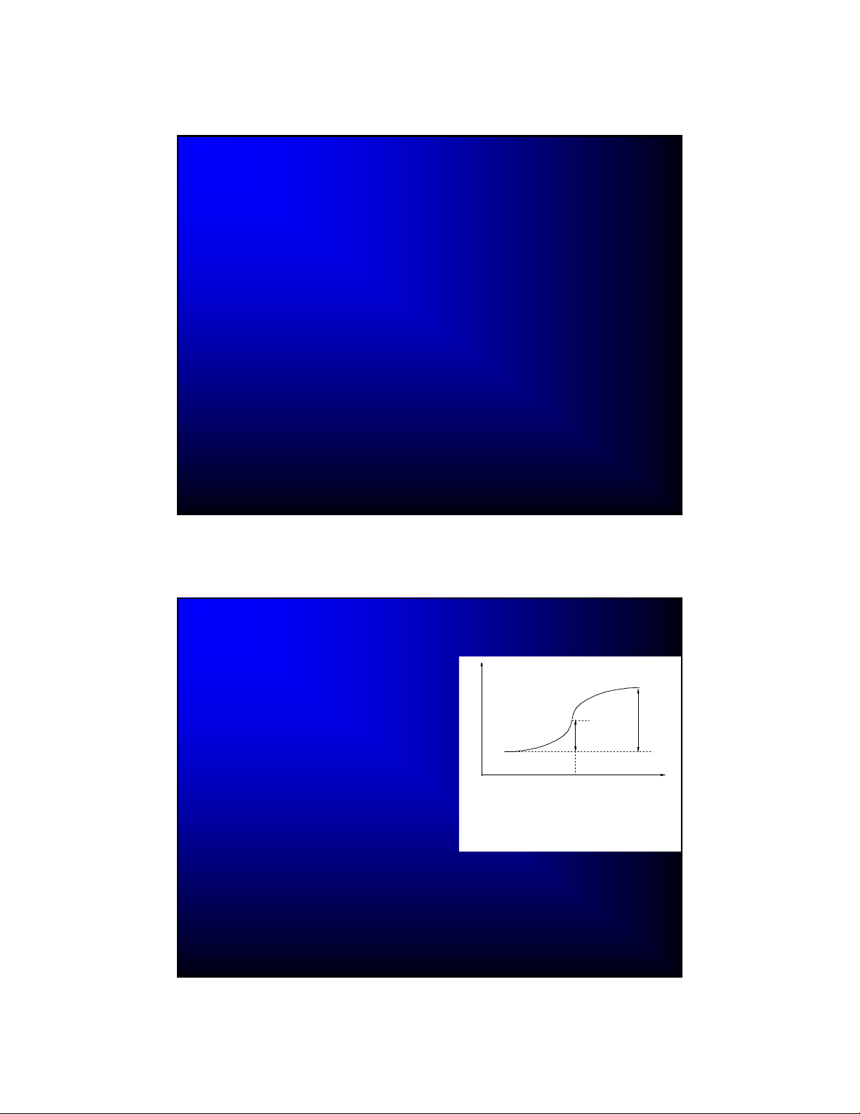
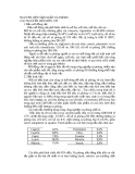
DC Polarography
The first voltammetric technique
(first instrument built in 1925)
DCP measures current flowing
through the dropping mercury
electrode (DME) as a function of
applied potential
Under the influence of gravity (or
other forces), mercury drops grow
from the end of a fine glass
capillary until they detach
If an electroactive species is
capable of undergoing a redox
process at the DME, then an S-
shaped current-potential trace (a
polarographic wave) is usually
observed
www.drhuang.com/.../polar.doc_files/image008.gif
4/30/2012
5
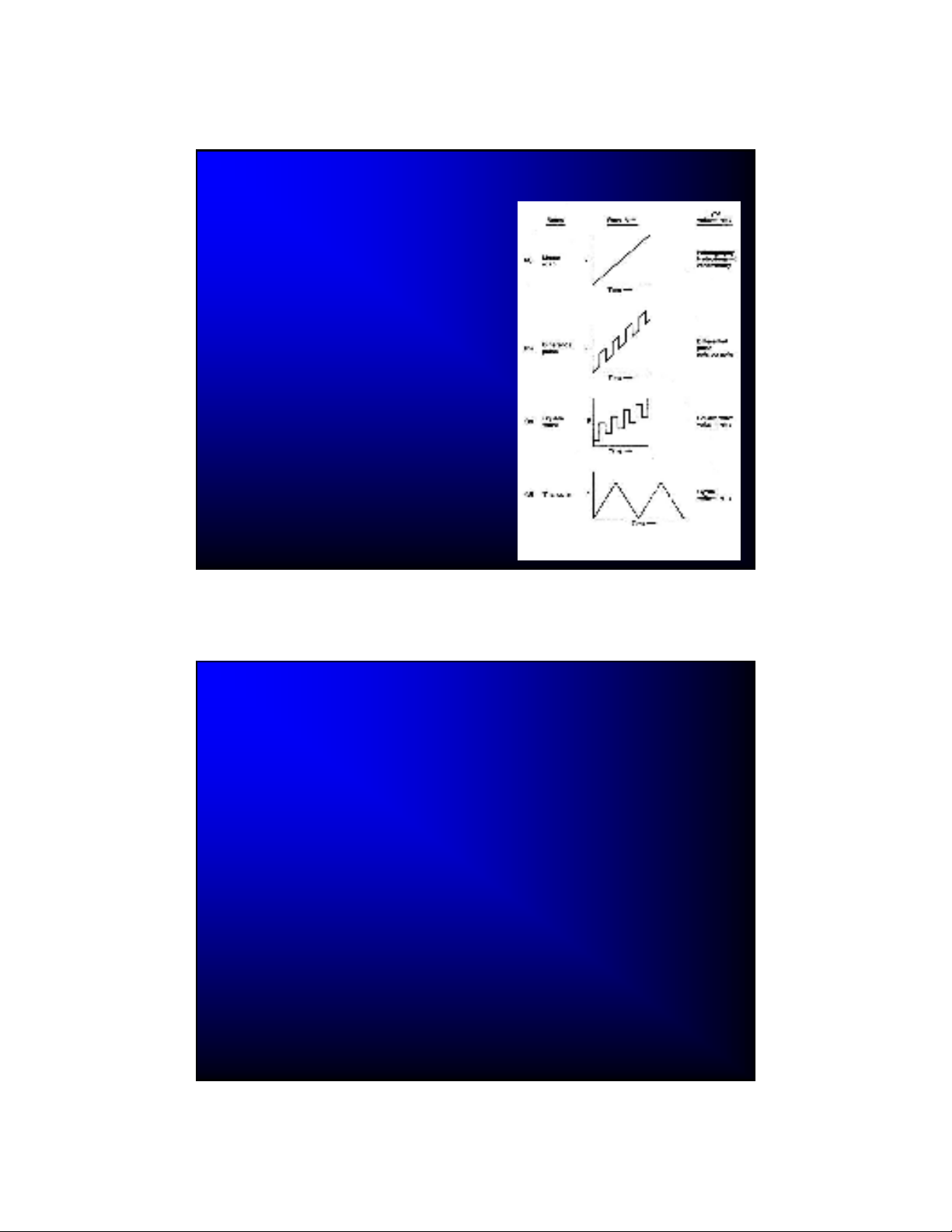
Voltage-Time Signals in Voltammetry
A variable potential
excitation signal is applied
to the working electrode
Different voltammetric
techniques use different
waveforms
Many other waveforms
are available (even FT
techniques are in use)
Linear Sweep Voltammetry
Linear sweep voltammetry (LSV) is performed by applying a
linear potential ramp in the same manner as DCP.
However, with LSV the potential scan rate is usually much
faster than with DCP.
When the reduction potential of the analyte is approached,
the current begins to flow.
– The current increases in response to the increasing
potential.
– However, as the reduction proceeds, a diffusion layer is
formed and the rate of the electrode reduction becomes
diffusion limited. At this point the current slowly declines.
The result is the asymmetric peak-shaped I-E curve


![Đề tài công nghệ silicat [mới nhất]](https://cdn.tailieu.vn/images/document/thumbnail/2011/20111018/vanalaya/135x160/thuy_tinh_slide_4642.jpg)


![Tài liệu học tập Thí nghiệm xử lý chất thải 1 (Chuyên ngành Kỹ thuật môi trường) [Mới nhất]](https://cdn.tailieu.vn/images/document/thumbnail/2026/20260512/hoatulip0906/135x160/94081778724718.jpg)

![Thiết bị phản ứng trong công nghiệp hóa dầu: Tài liệu [mô tả/hướng dẫn/kinh nghiệm]](https://cdn.tailieu.vn/images/document/thumbnail/2026/20260512/vispacex_27/135x160/2261778666802.jpg)


![Bài giảng Thiết kế công nghệ 4: Hệ thống trao đổi nhiệt 1 [Mới nhất]](https://cdn.tailieu.vn/images/document/thumbnail/2026/20260511/alfredodistefano10/135x160/83141778814944.jpg)

![Bài giảng Thiết kế công nghệ 3: Hệ thống tách chất [chuẩn nhất]](https://cdn.tailieu.vn/images/document/thumbnail/2026/20260511/alfredodistefano10/135x160/19631778814945.jpg)


%20--%3e%3cdefs%3e%3cstyle%3e%20.st0%20{%20fill:%20%23fff;%20}%20.st1%20{%20fill:%20%237800fa;%20}%20%3c/style%3e%3c/defs%3e%3cpath%20class='st1'%20d='M117.78,12.18H43.11c2.9,3.47,4.65,7.94,4.65,12.82,0,5.6-2.3,10.66-6.01,14.29h76.02l7.22-13.56-7.22-13.56Z'/%3e%3cg%3e%3cpath%20class='st0'%20d='M53.58,26.17h-.59v-1.46h.59v-4.96h2.83c1.78,0,2.67.94,2.67,2.82v5.76c0,1.87-.89,2.81-2.67,2.81h-2.83v-4.96ZM55.36,21.37v3.34h1.1v1.46h-1.1v3.34h1.01c.61,0,.91-.37.91-1.1v-5.93c0-.74-.3-1.1-.91-1.1h-1.01Z'/%3e%3cpath%20class='st0'%20d='M65.99,31.14h-1.8l-.31-2.07h-2.19l-.31,2.07h-1.64l1.82-11.39h2.62l1.82,11.39ZM65.28,18.04c-.25.46-.51.77-.75.94-.21.15-.47.22-.79.22-.26,0-.57-.07-.92-.22l-.38-.15c-.14-.05-.26-.07-.37-.07-.3,0-.53.18-.71.54l-.91-.68c.25-.46.51-.77.75-.94.21-.14.48-.21.79-.21.26,0,.57.07.92.21l.38.15c.14.05.26.07.37.07.3,0,.53-.18.71-.54l.91.68ZM61.91,27.52h1.73l-.87-5.76-.87,5.76Z'/%3e%3cpath%20class='st0'%20d='M74.53,26.89v1.52c0,1.91-.89,2.86-2.67,2.86s-2.67-.95-2.67-2.86v-5.93c0-1.91.89-2.86,2.67-2.86s2.67.95,2.67,2.86v1.11h-1.69v-1.22c0-.75-.31-1.12-.93-1.12s-.93.37-.93,1.12v6.15c0,.74.31,1.11.93,1.11s.93-.37.93-1.11v-1.63h1.69Z'/%3e%3cpath%20class='st0'%20d='M81.4,31.14h-1.8l-.31-2.07h-2.19l-.31,2.07h-1.64l1.82-11.39h2.62l1.82,11.39ZM75.9,19.2l1.52-1.91h1.71l1.51,1.91h-1.61l-.76-.95-.75.95h-1.61ZM77.32,27.52h1.73l-.87-5.76-.87,5.76ZM83.1,15.99l-1.76,1.91h-1.26l1.17-1.91h1.86Z'/%3e%3cpath%20class='st0'%20d='M84.86,19.75c1.78,0,2.67.94,2.67,2.82v1.48c0,1.87-.89,2.81-2.67,2.81h-.85v4.28h-1.79v-11.39h2.64ZM84.01,21.37v3.86h.85c.58,0,.87-.36.87-1.08v-1.71c0-.71-.29-1.07-.87-1.07h-.85Z'/%3e%3cpath%20class='st0'%20d='M93.51,19.75c1.78,0,2.67.94,2.67,2.82v1.48c0,1.87-.89,2.81-2.67,2.81h-.85v4.28h-1.79v-11.39h2.64ZM92.66,21.37v3.86h.85c.58,0,.87-.36.87-1.08v-1.71c0-.71-.29-1.07-.87-1.07h-.85Z'/%3e%3cpath%20class='st0'%20d='M98.8,31.14h-1.79v-11.39h1.79v4.88h2.03v-4.88h1.83v11.39h-1.83v-4.88h-2.03v4.88Z'/%3e%3cpath%20class='st0'%20d='M105.36,24.55h2.46v1.62h-2.46v3.34h3.09v1.63h-4.88v-11.39h4.88v1.63h-3.09v3.18ZM108.17,17.29l-1.76,1.91h-1.26l1.17-1.91h1.86Z'/%3e%3cpath%20class='st0'%20d='M112.2,19.75c1.78,0,2.67.94,2.67,2.82v1.48c0,1.87-.89,2.81-2.67,2.81h-.85v4.28h-1.79v-11.39h2.64ZM111.35,21.37v3.86h.85c.58,0,.87-.36.87-1.08v-1.71c0-.71-.29-1.07-.87-1.07h-.85Z'/%3e%3c/g%3e%3ccircle%20class='st1'%20cx='25'%20cy='25'%20r='20'/%3e%3cpath%20class='st0'%20d='M32.78,19.27c2.92,0,4.43,2.55,5.28,5.33l.71,2.17c.14.38-.33.75-.71.75h-5.61c.19-.33.24-.71.09-1.08l-.75-2.45c-.43-1.32-.99-2.64-1.79-3.77.75-.57,1.65-.94,2.78-.94h0ZM25,18.38c3.25,0,4.9,2.78,5.89,5.89l.76,2.45c.14.42-.33.8-.8.8h-11.69c-.42,0-.94-.38-.8-.8l.75-2.45c.99-3.11,2.64-5.89,5.89-5.89h0ZM25,11.35c1.74,0,3.11,1.37,3.11,3.11s-1.37,3.11-3.11,3.11-3.11-1.41-3.11-3.11,1.41-3.11,3.11-3.11h0ZM17.27,19.27c1.08,0,1.98.38,2.73.94-.8,1.13-1.37,2.45-1.74,3.77l-.8,2.45c-.14.38-.05.75.09,1.08h-5.56c-.42,0-.9-.38-.75-.75l.71-2.17c.9-2.78,2.41-5.33,5.33-5.33h0ZM17.27,12.91c1.51,0,2.78,1.27,2.78,2.83s-1.27,2.83-2.78,2.83-2.83-1.27-2.83-2.83,1.27-2.83,2.83-2.83h0ZM32.78,12.91c1.56,0,2.78,1.27,2.78,2.83s-1.23,2.83-2.78,2.83-2.83-1.27-2.83-2.83,1.27-2.83,2.83-2.83h0ZM27.07,28.56v.09c0,.57-.24,1.08-.61,1.46h0v.05c-.38.33-.9.57-1.46.57s-1.08-.24-1.46-.61h0c-.38-.38-.61-.9-.61-1.46v-.09h1.41v.09c0,.19.05.38.19.47v.05c.09.09.28.19.47.19s.38-.09.47-.19v-.05c.14-.09.24-.28.24-.47t-.05-.09h1.41ZM30.99,28.56v.09c0,1.65-.66,3.16-1.74,4.24-1.08,1.08-2.59,1.79-4.24,1.79s-3.16-.71-4.24-1.79l-.05-.05c-1.04-1.08-1.7-2.55-1.7-4.2v-.09h1.41v.09c0,1.27.47,2.4,1.27,3.25h.05c.85.85,1.98,1.37,3.25,1.37s2.4-.52,3.25-1.37c.85-.8,1.37-1.98,1.37-3.25v-.09h1.37ZM34.99,28.56v.09c0,2.78-1.13,5.28-2.92,7.07-1.79,1.79-4.29,2.92-7.07,2.92s-5.23-1.13-7.07-2.92c-1.79-1.79-2.92-4.29-2.92-7.07v-.09h1.41v.09c0,2.4.94,4.53,2.5,6.08,1.56,1.56,3.72,2.5,6.08,2.5s4.52-.94,6.08-2.5c1.56-1.56,2.5-3.68,2.5-6.08v-.09h1.41Z'/%3e%3c/svg%3e)