1
Ch4 ProgControllers 1
Ch. 5 Programmable Controllers
PLC/PC Overview
Siemens SIMATIC S7-x00 seri PLCs
STEP 7 – 300/400 Programming
Language
WinCC
Ch4 ProgControllers 2
5.1. Khái niệm PLCs
Lịch sử:
1960 – 1970s: Hard wire
1980 – 1990: Programmable Logic Controller
1990 – nay: Programmable Controller,
Process Controller
Các hãng sản xuất:
USA: Allen Bradley, GE-Fanuc
EC: Siemens, ABB, Schneider
As-Au: Omron, Hitachi, Misubishi…

2
Ch4 ProgControllers 3
Cấu trúc: chia thành các modules:
CPU, Power supply Module có cổng nối bộ
lập trình (PG)
[Expansion Memory Module (Flash, SRAM,
DRAM, BBRAM)]
Digital Input Module (mức áp dc/ac, cách ly
quang...)
Digital Output Module (relay, transistor,
triac..., Relay/Opto Isolated)
Analog Input Module (u, i, cách ly...)
Ch4 ProgControllers 4
Analog Output Module (u, i)
Timer/ Counter Module (kHz, đếm xung, đo
tốc độ, chiều dài)
Communication Module: (RS232/485;
Ethernet IEEE 802.x)
2/3 D Positioner Module (định vị 2/ 3 chiều)
Interface Module - dùng để mở rộng thêm
các Module khác
Function Modules: các chức năng điều khiển
PID, Servo/ Step Motors,...
3
Ch4 ProgControllers 5
Hoạt động của PLC:
Hoạt động theo chu kỳ các vòng quét:
Đọc các thông tin từ các lối vào: DI, AI, Counter,
Communication…
Xử lý, tính toán, Update data base, update các cờ
trạng thái
Gửi ra các port: DO, AO, Positioner,
Communication…
Ngôn ngữ lập trình:
Ladder
Statement List
Flow control
Ch4 ProgControllers 6
5.2. Siemens SIMATIC S7-x00 PLC:
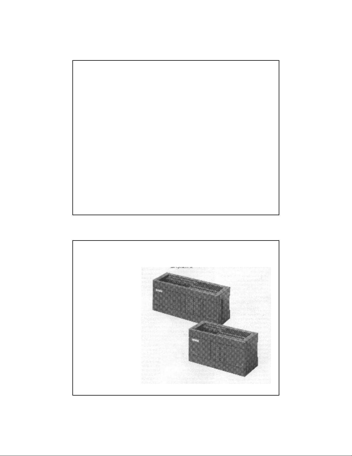
5.2.1. S7-200:
Hình 402.
PLC S7-200
4
Ch4 ProgControllers 7
Micro type, high-speed, compact, low-cost solution for
automation tasks within the low-end performance
range.
Có nhiều loại CPU: 212 (214…)
RAM for Program & data:
212 CPU: 1Kbyte – 512 statement, 2048 word data
214 CPU: 4Kbyte – 2048 statement, 2048 word data
Execution time of 1024Statements: 1,3ms (212CPU) và
0.8ms (214 CPU)
Bit memory: 128 (256)
Counters, Timer: 46 (128)
DI/DO max/onboard: 30/14 (64/24)
AI/AO max: 8 (16)
Communication: PPI
Real time clock: CPU 214.
Ch4 ProgControllers 8
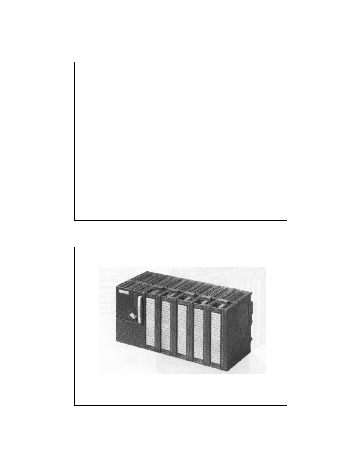
5.2.2. S7-300
Hình 403a – PLC S7-300
5
Ch4 ProgControllers 9
Mini PLC system, the custom solution for
extremely fast processes/ automation tasks
requiring additional data processing
capabilities
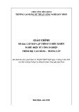
Spec.:
High computing performance,
Complete instruction set,
Multi Point Interface – MPI
5 CPUs for a wide variety of requirement
Expandability: up to 3 Expansion Racks (ERs)
Ch4 ProgControllers 10
![Giáo trình Matlab trong điều khiển tự động: Phần 2 [Full/Chi Tiết]](https://cdn.tailieu.vn/images/document/thumbnail/2020/20200827/nguathienthan7/135x160/1612429000.jpg)
![Giáo trình Matlab trong điều khiển tự động: Phần 1 [Full]](https://cdn.tailieu.vn/images/document/thumbnail/2020/20200827/nguathienthan7/135x160/1596479025.jpg)


![Giáo trình Đo lường và điều khiển máy tính: Phần 2 [Full]](https://cdn.tailieu.vn/images/document/thumbnail/2018/20180824/kaiyuan1121/135x160/6221535084969.jpg)


![Đề thi cuối kì Nhập môn Mạng máy tính: Tổng hợp [Năm]](https://cdn.tailieu.vn/images/document/thumbnail/2025/20251110/nminhthoi53@gmail.com/135x160/38281762757217.jpg)


![Đề thi học kì 2 môn Nhập môn Mạng máy tính [kèm đáp án]](https://cdn.tailieu.vn/images/document/thumbnail/2025/20251014/lakim0906/135x160/23811760416180.jpg)