
EURASIP Journal on Applied Signal Processing 2005:16, 2664–2672
c
2005 Hindawi Publishing Corporation
A Real-Time GPP Software-Defined Radio Testbed
for the Physical Layer of Wireless Standards
R. Schiphorst
The Signals and Systems Group, Department of Electrical Engineering, Faculty of EEMCS,
University of Twente, P.O. Box 217, 7500 AE Enschede, The Netherlands
Email: r.schiphorst@utwente.nl
F. W. Hoeksema
The Signals and Systems Group, Department of Electrical Engineering, Faculty of EEMCS,
University of Twente, P.O. Box 217, 7500 AE Enschede, The Netherlands
Email: f.w.hoeksema@utwente.nl
C. H. Slump
The Signals and Systems Group, Department of Electrical Engineering, Faculty of EEMCS,
University of Twente, P.O. Box 217, 7500 AE Enschede, The Netherlands
Email: c.h.slump@utwente.nl
Received 30 January 2004; Revised 23 September 2004
We present our contribution to the general-purpose-processor-(GPP)-based radio. We describe a baseband software-defined radio
testbed for the physical layer of wireless LAN standards. All physical layer functions have been successfully mapped on a Pentium
4 processor that performs these functions in real time. The testbed consists of a transmitter PC with a DAC board and a receiver
PC with an ADC board. In our project, we have implemented two different types of standards on this testbed, a continuous-
phase-modulation-based standard, Bluetooth, and an OFDM-based standard, HiperLAN/2. However, our testbed can easily be
extended to other standards, because the only limitation in our testbed is the maximal channel bandwidth of 20 MHz and of
course the processing capabilities of the used PC. The transmitter functions require at most 714 M cycles per second and the
receiver functions need 1225 M cycles per second on a Pentium 4 processor. In addition, baseband experiments have been carried
out successfully.
Keywords and phrases: software-defined radio, testbed, baseband, physical layer, HiperLAN/2, Bluetooth.
1. INTRODUCTION
New wireless communications standards do not replace old
ones; instead the number of standards keeps on increasing
and by now an abundance of standards already exists; see
Table 1. Moreover there is no reason to assume that this trend
will ever stop. Therefore the software-radio concept is emerg-
ing as a potential pragmatic solution: a software implemen-
tation of the user terminal able to dynamically adapt to the
radio environment in which the terminal is located [1].
Because of the analog nature of the air interface, a soft-
ware radio will always have an analog front end. In an ideal
software radio, the analog-to-digital converter (ADC) and
the digital-to-analog converter (DAC) are positioned directly
after the antenna. Such an implementation is not feasible
due to the power that this device would consume and other
physical limitations [2,3]. It is therefore a challenge to de-
sign a system that preserves most of the properties of the
ideal software radio while being realizable with current-day
technology. Such a system is called a software-defined radio
(SDR).
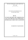
Software-defined radio has both advantages for
consumers and manufactures because current products
support only a fixed number of standards. Figure 1 shows
the lifetime of products and wireless standards. One can see
that products support a fixed number of standards and in
time new standards emerge and old ones disappear, making
a product eventually obsolete.
Software-defined radios on the other hand will enable
consumers to upgrade their radio with new functionality,
for example, required by new standards, just by software up-
dates, without the need for new hardware. Moreover, manu-
facturers can upgrade or improve functionality of consumer-
owned products and SDR could result in shorter devel-
opment time, cheaper production due to higher volumes.

A Real-Time GPP Software-Defined Radio Testbed 2665
Table 1: Overview of wireless standards [16].
Standard Frequency band Modulation type
CT2 864/868 MHz GFSK
CT2+ 944/948 MHz GFSK
DECT 1880–1900 MHz GFSK
PHS 1893–1920 MHz DQPSK
2402–2480 MHZ (North America)
GFSK
IEEE 802.15.4 2412–2472 MHz (Europe)
2483 MHz (Japan)
Bluetooth
2402–2480 MHz (North America and Europe)
GFSK
2447–2473 MHz (Spain)
2448–2482 MHz (France)
2473–2495 MHz (Japan)
HomeRF
2402–2480 MHz (North America and Europe)
GFSK
2447–2473 MHz (Spain)
2448–2482 MHz (France)
2473–2495 MHz (Japan)
5150–5250 MHz (USA)
IEEE 802.11a 5250–5350 MHz (USA) OFDM: 2/4/16/64 QAM
5725–5825 MHz (USA)
2410–2462 MHz (North America)
IEEE 802.11b 2412–2472 MHz (Europe) GFSK/DBPSK/DQPSK/QPSK
2483 MHz (Japan)
5150–5250 MHz (USA)
5250–5350 MHz (USA)
5725–5825 MHz (USA)
HiperLAN/2 5150–5350 MHz (Europe) OFDM: 2/4/16/64 QAM
5470–5725 MHz (Europe)
5725–5875 MHz (Europe)
5150–5250 MHz (Japan)
IS-54/IS-136
824–849 MHz
CDMA: π/4 DQPSK
869–894 MHz
1850–1910 MHz
1930–1990 MHz
IS-95
824–849 MHz
CDMA: QPSK/OQPSK
869–894 MHz
1850–1910 MHz
1930–1990 MHz
1920–1980 MHz (Asia only)
2110–2170 MHz (Asia only)
IMT-2000/UMTS
1920–1980 MHz
CDMA: QPSK
2110–2170 MHz
1900–1920 MHz
2010–2025 MHz

2666 EURASIP Journal on Applied Signal Processing
Table 1: Continued.
Standard Frequency band Modulation type
GSM
824–849 MHz
GMSK
869–894 MHz
880–915 MHz
925–960 MHz
1710–1785 MHz
1805–1880 MHz
1850–1910 MHz
1930–1990 MHz
PDC
810–826 MHz
π/4 DQPSK
940–956 MHz
1429–1441 MHz
1453–1465 MHz
1477–1489 MHz
1501–1513 MHz
Product I Product II Product IV
Standard 1
Standard 2
Standard 3 Product VI
Standard 4
Standard 5
Product III Standard 6
Product V Standard 7
···
Time
Standards
Figure 1: Standards support by products in time.
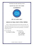
Physical layer
Medium access control
Logical link control
···
Protcols
Software
Hardware
Implementation
Figure 2: Mapping of protocols in current designs on hardware/
software.
However the downside of SDR will be power consumption
as dedicated designs are more power efficient which is very
important for mobile applications.
2. SOFTWARE-DEFINED RADIO
Figure 2 depicts the mapping in current radio designs of
the different OSI1layers on software/hardware. The physical
layer is generally implemented in hardware and higher layers
are often software based with the logical link control (LLC)
1Open system interconnection protocol model (OSI).
and medium access control (MAC) layer as a transition area.
In our SDR project [4], we research whether the lowest layer,
the physical layer, of wireless standards can be implemented
in software running on a general-purpose processor and es-
timate the costs of such an implementation with respect
to power consumption and computational power require-
ments.
So, we interpret SDR as an implementation technology
which differsfromtheviewsin[1,5], that is, flexible, univer-
sal, radio systems at each layer of the OSI model from which
manufacturers, network operators, and consumers can bene-
fit. Our interpretation of SDR is more focussed on the phys-
ical layer, an implementation technology, invisible for con-
sumers. Moreover we want to investigate if we can use exist-
ing processing capabilities (e.g., a notebook’s CPU) for dig-
ital signal processing purposes, thereby possibly prolonging
the lifetime of a device. This saves hardware and Moore’s law
will lower in time the computational load as a percentage of
the computational capacity.
A flexible, all-standard, radio will always consume more
energy than a dedicated radio; thus the first application for a
flexible radio; will be an application where power consump-
tion is less an issue, an example being a flexible radio in a

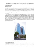
A Real-Time GPP Software-Defined Radio Testbed 2667
CPU DAC /
ADC
Wideband
analog front end
Notebook
Figure 3: Project scope.
notebook. This application for SDR has three advantages.
First, we can use the processing capabilities of the general-
purpose processor for digital signal processing purposes. Sec-
ond, in comparison to SDR for mobile phones, our demon-
strator can consume much more power (in the order of 1 W).
Third, a notebook is very suited for demonstration purposes.
Table 1 gives an overview of important wireless stan-
dards together with the used frequency bands and modula-
tion type. It seems that each standard can be seen as a fam-
ily of standards, an example being GSM. Thus the number
of existing standards that manufacturers have to support is
even larger than one would initially expect. However, there
are also similarities among them; the used frequency bands
are between 0.8 and 6 GHz with dominant frequency bands
around the 0.8 GHz, 2 GHz, 2.4 GHz, and 5 GHz. In addi-
tion, three types of transceivers are used, phase modulation,
OFDM (orthogonal frequency-division multiplexing), and
CDMA (code-division multiple access) transceivers.
In our SDR project, we decided not to focus on an all-
standard radio but to start with a software-defined radio for
wireless LAN standards first. The research is carried out by
two chairs of the University of Twente: the IC-Design group
which focusses on the RF part and the Signals and Systems
group focussing on the baseband part. At the project’s start
we also defined the scope of the project: the physical layer
excluding error-correction encoding/decoding. Recent liter-
ature [6] indicates, however, that especially error-correction
decoding (Viterbi algorithm) requires most of the computa-
tional power in the lower layers of a system. Figure 3 sum-
marizes the design goal of our project, a notebook with a
wideband RF front end with a software implementation of
the physical layer.
Wireless LAN standards use phase modulation or OFDM
in the 2.4 GHz or 5 GHz frequency band, so we decided in
our project to combine an instance of a phase-modulation
standard (Bluetooth) with an OFDM standard (Hiper-
LAN/2). Table 2 shows some characteristics of the physical
layer of both standards. HiperLAN/2 is a high-speed wire-
less LAN (WLAN) standard using OFDM. Its physical layer is
very similar to the 802.11a standard. Bluetooth on the other
hand is a low-cost, low-speed standard, designed for replac-
ing fixed cables. Bluetooth uses continuous-phase modula-
tion, Gaussian frequency shift keying (GFSK) which is also
used by other standards such as HomeRF and DECT.
This paper discusses only the digital baseband part of
the project. More information about the total project can
be found in [7] or at the project’s website [4]. The rest of
the paper is organized as follows. First the functional archi-
tecture of the physical layer of both standards is discussed,
which is followed by a description of the testbed. This paper
concludes by presenting real-world measurements done with
the testbed.
3. SDR BASEBAND TESTBED
In the first phase of the project, we built two separate re-
ceivers [8] in order to gain knowledge. After the first phase,
we concluded that a real-time software implementation of
the physical layer functions of the transmitter and receiver
on a Pentium 4 processor was possible. Therefore we started
in the second phase of the project with a real-time software
implementation of the Bluetooth and HiperLAN/2 receiver
and transmitter.
Although we show that a real-time software implementa-
tion of the receiver (and transmitter) functionality is possible
using the notebook’s processor, it requires, besides process-
ing power, a real-time operating system. Traditional operat-
ing systems such as Windows or Linux are non-real time; for
example, the latency of the system is undefined and can be
up to 100 milliseconds for Linux [9]. So it is possible that
our receiver program misses a buffer and data is lost. How-
ever, special patches can be applied to the Linux kernel for
example, which reduces this maximal latency to about 5 mi-
croseconds [9].2In our testbed, we use large sample buffers
of 100 milliseconds to avoid the influence of the operating
system but additional research is needed to find the maximal
allowable latency which is probably determined by the MAC
layer. Furthermore, we have to investigate if this value can be
achieved in our testbed. So at the moment, our testbed can
only be used for continuous transmission of MAC bursts.
3.1. Functional architecture
Figure 4 depicts the functional architecture of the Bluetooth
transmitter and receiver. The first step in the transmitter is to
embed the raw bits into MAC bursts which are then BPSK
modulated at 1 Mbp. The BPSK symbols are filtered by a
Gaussian lowpass filter and the filtered output is connected to
VCO that translates the amplitude variation into frequency
variations. At the receiver side, the first step is to select the
wanted Bluetooth channel and suppress all others which is
performed both digitally and by the analog front end. This
is achieved by mixing the wanted channel to baseband and
applying a lowpass filter. The next step is to demodulate the
FM signal into an AM signal by taking the derivative of the
phase. Because a frequency offset introduces an offset in the
AM signal, it has to be corrected before bit decision.
On the other hand, Figure 5 depicts the HiperLAN/2
physical layer architecture which is very different from the
Bluetooth architecture one. The HiperLAN/2 transmitter
starts with mapping raw bits on BPSK, QPSK, 16-QAM, or
64-QAM symbols, depending on the used mode. In the next
step, the QAM symbols are mapped on data carriers and an
OFDM symbol is constructed by adding pilot carriers, ap-
plying an inverse FFT, and adding a prefix, which results in
2A HiperLAN/2 MAC frame has a Duration of 2 milliseconds and the
shortest Bluetooth MAC frame is 0.625-millisecond long.

2668 EURASIP Journal on Applied Signal Processing
Table 2: Some physical layer characteristics of Bluetooth and HiperLAN/2.
Parameter Bluetooth HiperLAN/2
Band 2.4–2.48 GHz 5.15–5.725 GHz
Channel spacing 1 MHz 20 MHz
Modulation GFSK OFDM: BPSK/QPSK/16 QAM/64 QAM
Nominal bit rate (no FEC) 172.8–723.2 kbps 12–72 Mbps
Raw
bits
MAC burst
generation
BPSK
modulator
Gaussian
filter VCO
t[k]
(a)
r[k]
Channel selection
Mixing Lowpass
filter
FM-to-AM
converter
Frequency
offset
correction
Decision
Synchronization
Raw
bits
(b)
Figure 4: Functional architecture of the Bluetooth (a) transmitter and (b) receiver (functional layer excluding error-correction encod-
ing/decoding).
Raw
bits
QAM
mapping
64-point
IFFT
Prefix
insertion
Preambles
Control
t[k]
(a)
r[k]
Frequency
offset
correction
64-point
FFT
Channel
equalization
Phase offset
estimation/
correction
QAM
demapping
Synchronization/parameter estimation
Raw
bits
(b)
Figure 5: Functional architecture of the HiperLAN/2 (a) transmitter and (b) receiver (functional layer excluding error-correction encod-
ing/decoding).
r[k]Sample rate
reduction
HiperLAN/2 mode
Bluetooth mode
Frequency
offset
correction
Mixing
64-point
FFT
Lowpass
filter
Channel
equalization
Frequency
offset
correction
Phase
offset
correction
QAM
demodulation
MAP receiver
Synchronization/parameter estimation
Raw
bits
Figure 6: Functional architecture of the Bluetooth-enabled HiperLAN/2 receiver (functional layer excluding error-correction encod-
ing/decoding).
a 20-MSPS signal. MAC bursts are then created by adding
special symbols, preambles, to the start of the MAC burst.
The HiperLAN/2 receiver starts by searching for the start
of an MAC burst. If it is found, it estimates the frequency
offset and channel parameters. After these steps, the data
OFDM symbols can be demodulated by first correcting the
frequency offset, performing an FFT, correcting the channel,
and detecting and correcting the phase offset by using the
pilot tones. The output is QAM symbols which have to be
demapped into raw bits.
Although the functional architecture of both standards
is very different, we have successfully integrated the Blue-
tooth receiver functionality into the HiperLAN/2 receiver
[10](Figure 6) by using a (simplified) maximum a posteriori

![Thuyết minh tính toán kết cấu đồ án Bê tông cốt thép 1: [Mô tả/Hướng dẫn/Chi tiết]](https://cdn.tailieu.vn/images/document/thumbnail/2016/20160531/quoccuong1992/135x160/1628195322.jpg)


%20--%3e%3cdefs%3e%3cstyle%3e%20.st0%20{%20fill:%20%23fff;%20}%20.st1%20{%20fill:%20%237800fa;%20}%20%3c/style%3e%3c/defs%3e%3cpath%20class='st1'%20d='M117.78,12.18H43.11c2.9,3.47,4.65,7.94,4.65,12.82,0,5.6-2.3,10.66-6.01,14.29h76.02l7.22-13.56-7.22-13.56Z'/%3e%3cg%3e%3cpath%20class='st0'%20d='M53.58,26.17h-.59v-1.46h.59v-4.96h2.83c1.78,0,2.67.94,2.67,2.82v5.76c0,1.87-.89,2.81-2.67,2.81h-2.83v-4.96ZM55.36,21.37v3.34h1.1v1.46h-1.1v3.34h1.01c.61,0,.91-.37.91-1.1v-5.93c0-.74-.3-1.1-.91-1.1h-1.01Z'/%3e%3cpath%20class='st0'%20d='M65.99,31.14h-1.8l-.31-2.07h-2.19l-.31,2.07h-1.64l1.82-11.39h2.62l1.82,11.39ZM65.28,18.04c-.25.46-.51.77-.75.94-.21.15-.47.22-.79.22-.26,0-.57-.07-.92-.22l-.38-.15c-.14-.05-.26-.07-.37-.07-.3,0-.53.18-.71.54l-.91-.68c.25-.46.51-.77.75-.94.21-.14.48-.21.79-.21.26,0,.57.07.92.21l.38.15c.14.05.26.07.37.07.3,0,.53-.18.71-.54l.91.68ZM61.91,27.52h1.73l-.87-5.76-.87,5.76Z'/%3e%3cpath%20class='st0'%20d='M74.53,26.89v1.52c0,1.91-.89,2.86-2.67,2.86s-2.67-.95-2.67-2.86v-5.93c0-1.91.89-2.86,2.67-2.86s2.67.95,2.67,2.86v1.11h-1.69v-1.22c0-.75-.31-1.12-.93-1.12s-.93.37-.93,1.12v6.15c0,.74.31,1.11.93,1.11s.93-.37.93-1.11v-1.63h1.69Z'/%3e%3cpath%20class='st0'%20d='M81.4,31.14h-1.8l-.31-2.07h-2.19l-.31,2.07h-1.64l1.82-11.39h2.62l1.82,11.39ZM75.9,19.2l1.52-1.91h1.71l1.51,1.91h-1.61l-.76-.95-.75.95h-1.61ZM77.32,27.52h1.73l-.87-5.76-.87,5.76ZM83.1,15.99l-1.76,1.91h-1.26l1.17-1.91h1.86Z'/%3e%3cpath%20class='st0'%20d='M84.86,19.75c1.78,0,2.67.94,2.67,2.82v1.48c0,1.87-.89,2.81-2.67,2.81h-.85v4.28h-1.79v-11.39h2.64ZM84.01,21.37v3.86h.85c.58,0,.87-.36.87-1.08v-1.71c0-.71-.29-1.07-.87-1.07h-.85Z'/%3e%3cpath%20class='st0'%20d='M93.51,19.75c1.78,0,2.67.94,2.67,2.82v1.48c0,1.87-.89,2.81-2.67,2.81h-.85v4.28h-1.79v-11.39h2.64ZM92.66,21.37v3.86h.85c.58,0,.87-.36.87-1.08v-1.71c0-.71-.29-1.07-.87-1.07h-.85Z'/%3e%3cpath%20class='st0'%20d='M98.8,31.14h-1.79v-11.39h1.79v4.88h2.03v-4.88h1.83v11.39h-1.83v-4.88h-2.03v4.88Z'/%3e%3cpath%20class='st0'%20d='M105.36,24.55h2.46v1.62h-2.46v3.34h3.09v1.63h-4.88v-11.39h4.88v1.63h-3.09v3.18ZM108.17,17.29l-1.76,1.91h-1.26l1.17-1.91h1.86Z'/%3e%3cpath%20class='st0'%20d='M112.2,19.75c1.78,0,2.67.94,2.67,2.82v1.48c0,1.87-.89,2.81-2.67,2.81h-.85v4.28h-1.79v-11.39h2.64ZM111.35,21.37v3.86h.85c.58,0,.87-.36.87-1.08v-1.71c0-.71-.29-1.07-.87-1.07h-.85Z'/%3e%3c/g%3e%3ccircle%20class='st1'%20cx='25'%20cy='25'%20r='20'/%3e%3cpath%20class='st0'%20d='M32.78,19.27c2.92,0,4.43,2.55,5.28,5.33l.71,2.17c.14.38-.33.75-.71.75h-5.61c.19-.33.24-.71.09-1.08l-.75-2.45c-.43-1.32-.99-2.64-1.79-3.77.75-.57,1.65-.94,2.78-.94h0ZM25,18.38c3.25,0,4.9,2.78,5.89,5.89l.76,2.45c.14.42-.33.8-.8.8h-11.69c-.42,0-.94-.38-.8-.8l.75-2.45c.99-3.11,2.64-5.89,5.89-5.89h0ZM25,11.35c1.74,0,3.11,1.37,3.11,3.11s-1.37,3.11-3.11,3.11-3.11-1.41-3.11-3.11,1.41-3.11,3.11-3.11h0ZM17.27,19.27c1.08,0,1.98.38,2.73.94-.8,1.13-1.37,2.45-1.74,3.77l-.8,2.45c-.14.38-.05.75.09,1.08h-5.56c-.42,0-.9-.38-.75-.75l.71-2.17c.9-2.78,2.41-5.33,5.33-5.33h0ZM17.27,12.91c1.51,0,2.78,1.27,2.78,2.83s-1.27,2.83-2.78,2.83-2.83-1.27-2.83-2.83,1.27-2.83,2.83-2.83h0ZM32.78,12.91c1.56,0,2.78,1.27,2.78,2.83s-1.23,2.83-2.78,2.83-2.83-1.27-2.83-2.83,1.27-2.83,2.83-2.83h0ZM27.07,28.56v.09c0,.57-.24,1.08-.61,1.46h0v.05c-.38.33-.9.57-1.46.57s-1.08-.24-1.46-.61h0c-.38-.38-.61-.9-.61-1.46v-.09h1.41v.09c0,.19.05.38.19.47v.05c.09.09.28.19.47.19s.38-.09.47-.19v-.05c.14-.09.24-.28.24-.47t-.05-.09h1.41ZM30.99,28.56v.09c0,1.65-.66,3.16-1.74,4.24-1.08,1.08-2.59,1.79-4.24,1.79s-3.16-.71-4.24-1.79l-.05-.05c-1.04-1.08-1.7-2.55-1.7-4.2v-.09h1.41v.09c0,1.27.47,2.4,1.27,3.25h.05c.85.85,1.98,1.37,3.25,1.37s2.4-.52,3.25-1.37c.85-.8,1.37-1.98,1.37-3.25v-.09h1.37ZM34.99,28.56v.09c0,2.78-1.13,5.28-2.92,7.07-1.79,1.79-4.29,2.92-7.07,2.92s-5.23-1.13-7.07-2.92c-1.79-1.79-2.92-4.29-2.92-7.07v-.09h1.41v.09c0,2.4.94,4.53,2.5,6.08,1.56,1.56,3.72,2.5,6.08,2.5s4.52-.94,6.08-2.5c1.56-1.56,2.5-3.68,2.5-6.08v-.09h1.41Z'/%3e%3c/svg%3e)