REGULAR ARTICLE
Possible in-vessel corium progression way in the Unit 1
of Fukushima Dai-ichi nuclear power plant using
a phenomenological analysis
Frédéric Payot
1,*
and Jean-Marie Seiler
2
1
CEA Cadarache/DTN/SMTA/LPMA, 13108 Saint-Paul-lez-Durance cedex, France
2
CEA Grenoble/DTN/STCP/LTDA, 17, rue des Martyrs, 38054 Grenoble cedex 9, France
Received: 28 April 2015 / Received in nal form: 7 July 2015 / Accepted: 15 September 2015
Published online: 05 December 2015
Abstract. In the eld of severe accident, the description of corium progression events is mainly carried out by
using integral calculation codes. However, these tools are usually based on bounding assumptions because of high
complexity of phenomena. The limitations associated with bounding situations ([J.M. Seiler, B. Tourniaire,
A phenomenological analysis of melt progression in the lower head of a pressurized water reactor, Nucl. Eng. Des.
268, 87 (2014)] e.g. steady state situations and instantaneous whole core relocation in the lower head) led CEA to
develop an alternative approach in order to improve the phenomenological description of melt progression. The
methodology used to describe the corium progression was designed to cover the accidental situations from the
core meltdown to the molten core concrete interaction. This phenomenological approach is based on available
data (including learnings from TMI2), on physical models and knowledge about the corium behavior. It provides
emerging trends and best estimated intermediate situations. As different phenomena are unknown, but strongly
coupled, uncertainties at large scale for the reactor application must be taken into account. Furthermore, the
analysis is complicated by the fact that these congurations are most probably three dimensional, all the more so
because 3D effects are expected to have signicant consequences for the corium progression and the resulting
vessel failure. Such an analysis of the in-vessel melt progression was carried out for the Unit 1 of the Fukushima
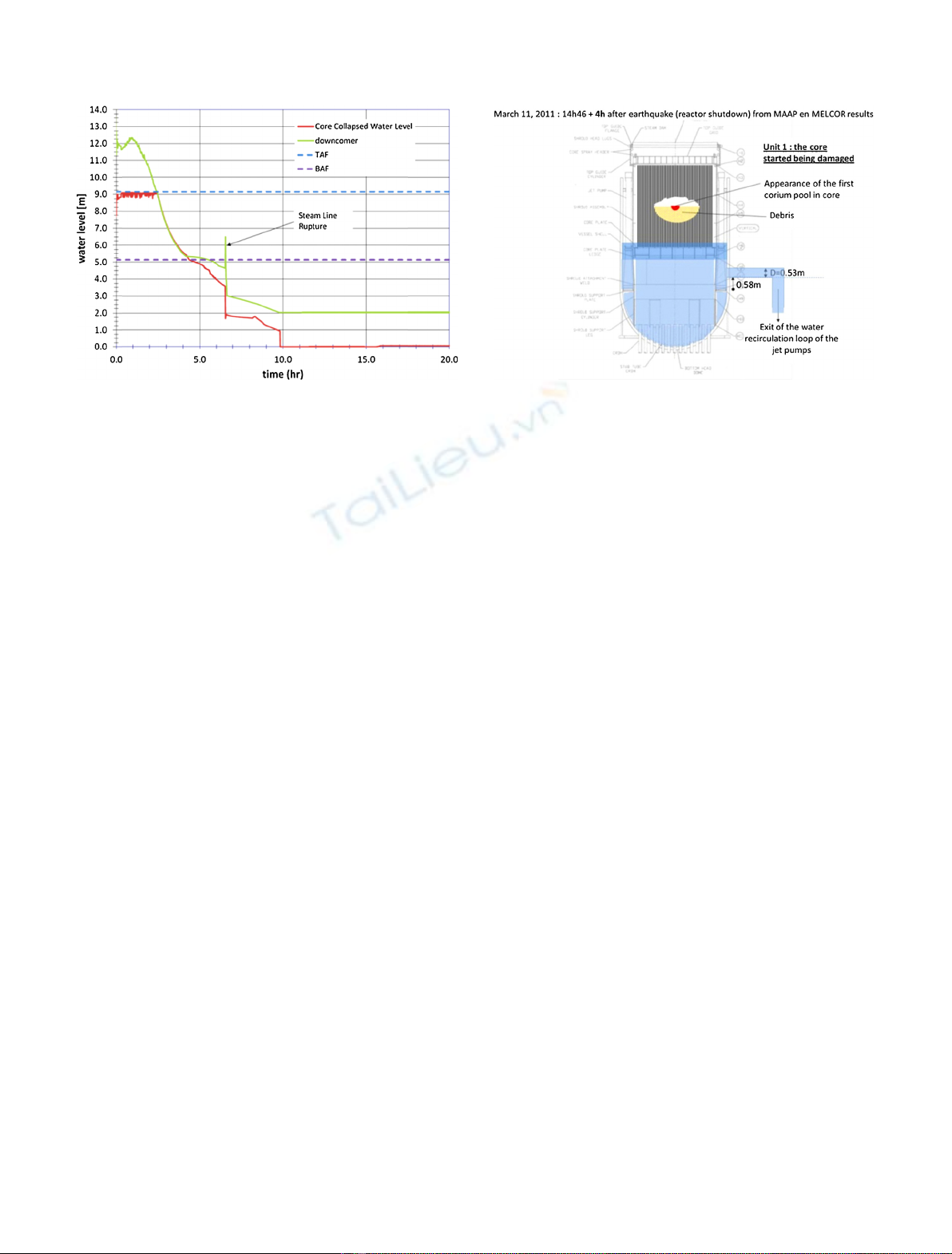
Dai-ichi nuclear power plant. The core uncovering kinetics governs the core degradation and impacts the
appearance of the rst molten corium inside the core. The initial conditions used to carry out this analysis are
based on available results derived from codes like MELCOR calculation code [R. Ganntt, D. Kalinich, J. Cardoni,
J. Phillips, A. Goldmann, S. Pickering, M. Francis, K. Robb, L. Ott, D. Wang, C. Smith, S. St. Germain,
D. Schwieder, S. Phelan, Fukushima Daiichi Accident Study (Status as of April 2012), Sandia Report Sand 2012-
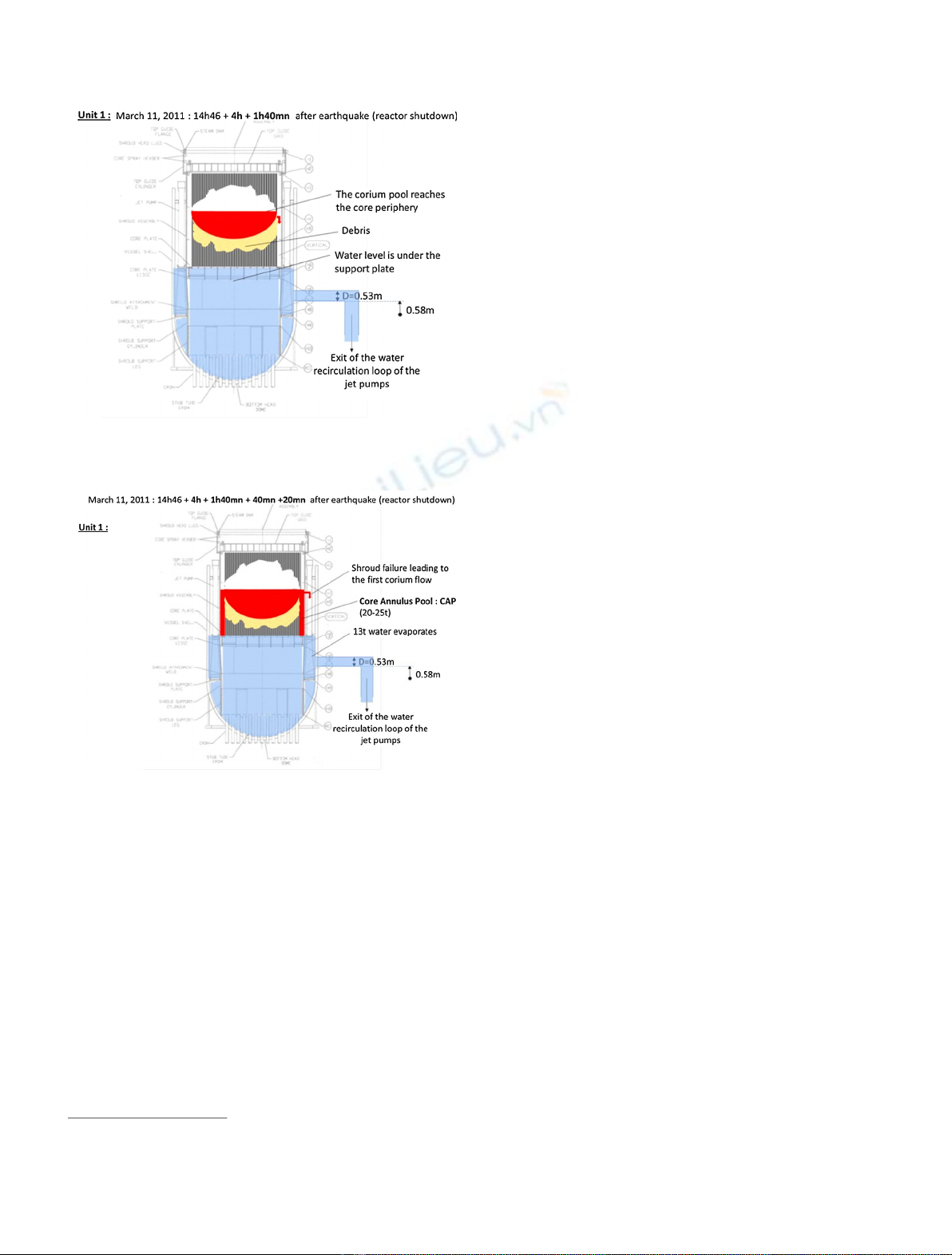
6173, Unlimited Release Printed August, 2012]. The core degradation could then follow different ways: axial
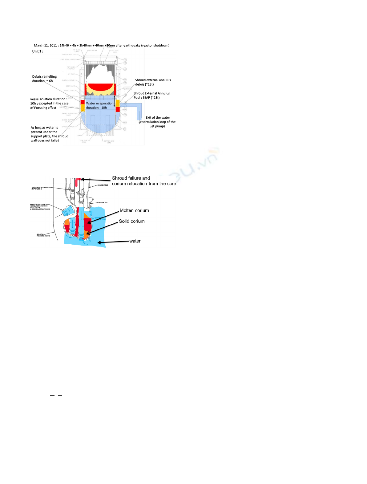
progression of the debris and the molten fuel through the lower support plate; lateral progression of the molten
fuel through the shroud. On the basis of the Bali program results [J.M. Bonnet, An integral model for the
calculation of heat ux distribution in a pool with internal heat generation, in Nureth7 530 Conference Saratoga
Springs, NY, USA, September 1015, 1995 (1995)] and the TMI-2 accident observations [D.W. Ackers, J.R. Wolf,
Relocation of Fuel Debris to the Lower Head of the TMI2 Reactor Vessel-A possible scenario, TMI 2 pressure
vessel investigation project, in Proceedings of the Open forum OECD/NEA and USNRCm, Boston, USA, 2022
October 1993 (1993)], this work is focused on the consequences of a lateral melt progression (not excluding an
axial progression through the support plate). Analysis of the events and the associated time sequence will be
detailed. Besides, this analysis identies a number of issues. Random calculations and statistical analysis of the
results could be performed with calculation codes such as LEONARPROCOR codes [R. Le Tellier, L. Saas, F.
Payot, Phenomenological analyses of corium propagation in LWRs: the PROCOR software platform, in
ERMSAR 2015, Marseille, France, 2426 March, 2015 (2015)].
* e-mail: frederic.payot@cea.fr
EPJ Nuclear Sci. Technol. 1, 7 (2015)
©F. Payot and J.-M. Seiler, published by EDP Sciences, 2015
DOI: 10.1051/epjn/e2015-50001-5
Nuclear
Sciences
& Technologies
Available online at:
http://www.epj-n.org
This is an Open Access article distributed under the terms of the Creative Commons Attribution License (http://creativecommons.org/licenses/by/4.0),
which permits unrestricted use, distribution, and reproduction in any medium, provided the original work is properly cited.
1 Introduction
The three accidents (i.e. accidents in Units 1, 2, and 3) led
to different degrees of core damage, with Unit 1 being
probably the most severely damaged of the three [1]. The
rst conjectures about the Unit 1 core damage assumed a
vessel lower head failure, a core material release into the
containment cavity, and core-concrete interactions likely
initiated. Units 2 and 3 are likely less damaged [2,3].
The description of corium progression events is mainly
carried out by the mechanistic calculation codes. The safety
demonstrations (e.g. AP1000 [4]) using these codes are
usually based on bounding situations because of high
complexity of phenomena. The limitations associated to
bounding situations (e.g. problem of the focusing effect
during the transient formation and steady state situations)
led CEA [5] to develop, together with EDF, an alternative
phenomenological approach (so-called phenomenological
approach) in order to supplement the current severe
accident calculation codes [6].
The phenomenological approach developed in order to
describe the corium progression covers the accidental
situations from the core melting propagation down to the
Molten Core Concrete Interaction (MCCI) in LWRs. This
approach was elaborated from physical models and
knowledge concerning the corium behavior, which provides
emerging trends and plausible best estimatesequences.
The analysis is complicated by the fact that phenomena are
sometimes unknown and highly coupled at various scales.
Moreover, these corium congurations in the lower head are
most probably three dimensional, all the more so because
local and non-axisymmetric effects are expected to have
signicant consequences for the vessel failure and corium
release conditions into the reactor pit.
These last years, phenomenological approachstudies
were rst concentrated on the French 1300 MWe PWR,
considering both dry scenarios and the possibility of ooding
of the primary circuit and/or the reactor pit. BWR reactors
were also studied which provided the piece of information to
analyze the in-vessel corium progression scenario in the Unit
1 of Fukushima Dai-ichi nuclear power plant.
Such an analysis of the in-vessel melt progression was
carried out for the Unit 1 of the Fukushima Dai-ichi nuclear
power plant. In the event timeline, the core uncovering
velocity led to the core degradation of the Unit 1. As an
assumption, without additional water injection, the rst
core degradation events are the control rod liquefaction and
downward relocation of the B
4
C and stainless steel, and fuel
debris, in the lower core region. Then, the partial fuel
melting could give rise to the appearance of the rst corium
pool in the centre of the core, as described by the MELCOR
calculation code [2]. From that time, the core degradation
scenario could follow different ways [7] according to the in-
vessel melt progression, i.e.:
axial progression of the debris and the molten fuel
through the lower support plate and/or;
lateral progression of the molten fuel through the shroud.
It is possible that both previous events did occur
sequentially during the accident. In the following, we will
develop the scenario based on lateral corium ow through
the shroud.
The objective of this paper is to describe the alternative
relocation path taking into account local and non-
axisymmetric effects. Several issues will be addressed such
as the thermal loads on the shroud, the location and time
delay to vessel failure and corium conguration in the lower
head at vessel failure. Besides, this analysis identies a
number of open issues.
The models which have been derived from this analysis
have recently been implemented in the PROCOR Platform
[6], which is used for LWR reactor calculations. This
calculation tool includes statistical evaluations (probability
of occurrence, impact of uncertainties, and identication of
most important parameters).
This work was presented in the frame of the OECD/
NEA/CSNI Benchmark Study of the Accident at the
Fukushima Dai-ichi Nuclear Power Station (BSAF) project
[8]. During 2012 and 2014 years, the purpose of this project
was both to study, by mean of severe accident codes, the
Fukushima accident in the three crippled units, until six days
from the reactor shut-down and to give information about in
particular the location and composition of core debris.
2 Methodology
The initial conditions used to carry out this analysis are
based on partial core melting with an initial corium pool
formed in the core. This core degradation state (e.g.
amount, location, power, of melt corium pool, etc.) is
described by existing codes, as for example, the MAAP and
MELCOR calculation codes. The appearance of the rst
corium pool is strongly dependent on the kinetics of the core
uncovery. During the Unit 1 damage sequence, available
water levels in the core are not reliable. We will use data
provided by the MELCOR calculation code [2].
Then the phenomenological evaluation is conducted
step by step following the corium relocation path:
in the core region:
a new situation (compared to computational results) is
carried out which corresponds to the kinetics of the melt
corium growth, to the relocation in the space between
core and shroud and to the ablation of shroud and of the
core support plate. These phenomena depend on the
presence of water, whose late injection conditions are
also not well known;
in the vessel lower part:
evolution of the corium masses released into the vessel
lower part, taking into account the occurrence of
several corium ows at various time intervals;
the formation of debris, the impact of focusing effect,
the variations in the thermal loads and heating up of
the vessel wall are evaluated in the presence of residual
water;
the time until vessel failure, thermal loads at this time
and failure conditions are also evaluated (location,
mass of corium, etc.) for dry ex-vessel situation.
2 F. Payot and J.-M. Seiler: EPJ Nuclear Sci. Technol. 1, 7 (2015)
3 Core degradation and core melt progression
In the Unit 1 accident, as with all of the affected reactors,
following the earthquake, the reactor shutdown was
accomplished on March 11, 2011 at 14:46.
According to the MELCOR calculations [2], the loss of
cooling water leads to core uncover 2 h 30 after the reactor
shutdown, within a short period of time as shown in
Figure 1. From there, the core is not sufciently cooled and
the cladding and fuel heatup follows. When the core
temperature reaches between 1000 K and 1200 K, cladding
failure is possible. Indeed, the temperature of the Zircaloy
(Zr) cladding can escalate to its melting temperature, which
would cause cladding failure and relocation. The Zr
oxidation reaction, once started, leads to fast escalation
in fuel temperature. Interaction between fuel, cladding and
other structural materials leads to the formation of molten
material at temperatures possibly below the individual
melting points of the respective materials. This molten
material relocates within the core.
In Unit 1, in the absence of adequate core cooling, core
degradation leads to a large mass of debris relocating within
the lower regions of the core and/or settling on the lower
core support plate. Also, molten pools could form within the
debris, located in the centre of the core. From the MELCOR
results, the appearance of the rst liquid corium pool could
occur 4 h after the reactor shutdown as illustrated in
Figure 2. At this time, the water level could be located just
above the core support plate.
The kinetics of corium pool growth in a debris bed (see
[5]) is governed by two contributions:
debris melting due to the heat ux at the molten pool
boundaries (linked to power dissipation in the corium
pool (volume power dissipation q0.6 MW/m
3
);
heating and melting of the debris under the effect of
residual power in the solid debris.
The molten pool tends to propagate radially, due to
heat-ux distribution linked to internal natural convection
[9]. Indeed, the lateral heat ux of a corium pool is about
one order of magnitude higher than downward heat ux,
which limits the axial propagation rate of the corium pool
(see Appendix A). Axial melt progression rate is, thus,
reduced in comparison with lateral melt progression. In this
situation, the corium pool could be supported, during the
transient melt progression, by the debris bed and solid
relocation in the lower part of the core (Fig. 2). Axial
propagation of melt is mainly controlled by debris heat-up
and corium relocation in the lower part of the core, but the
heat ux from the pool does not contribute signicantly to
axial progression. Besides, it is important to underline that
the downward melt progression is also limited by corium
freezing and signicant formation of debris from the
structure degradation in the lower parts of the core (due
to the presence of water and low hydraulic diameter).
Typically, the whole core meltdown process (i.e. 120 t
of oxidic corium from fuel and Zircaloy) could take 5h
under dry conditions (after complete core uncovery).
We consider that the corium pool surface was located at
the core center i.e. height equal to 2 m from the lower
support plate (Fig. 2). Due to the tendency of the corium
pool to propagate radially, as previously explained, the
molten pool could reach the peripheral sub-assemblies
before the lower part of the core is molten, as illustrated in
Figure 3. When the pool reaches the outer core assemblies,
there is no obstacle for the melt to relocate between the core
and the shroud (5 h 40 after the reactor shutdown). A
relocated melt pool can thus form in this space, which we
will call the Core Annulus Pool or CAP (Fig. 4).
The distance between the external core sub-assemblies
and the shroud is azimuthally not uniformly distributed,
but is of the order of 0.1 to 0.20 m (mean value:
0.16 m). A signicant proportion of core (2025 t out of
120 t) could relocate between the core and the shroud.
The level of corium in this annular space is supposed to
reach the same level as the corium pool level in the core, as
illustrated in Figure 4. The duration of this sequence is
estimated to be 40 min.
Meanwhile, we assume that the residual water level
reaches the core support plate. In the following section, a
Fig. 1. MELCOR prediction of water level evolution in the
reactor core and downcomer regions (Unit 1) [2].
Fig. 2. Illustration of the appearance of the rst corium pool in
the core: 4 h after the reactor shutdown.
F. Payot and J.-M. Seiler: EPJ Nuclear Sci. Technol. 1, 7 (2015) 3
scenario with the presence of residual water below the core
support plate, in the vessel lower head region, is assumed.
4 Core annulus pool formation
The corium accumulation duration in the CAP could take
40 min. During this period, no water is present on the
outside of the shroud. With a small lateral heat ux
towards the shroud (order of magnitude
1
:0.03 MW/m
2
;),
the shroud thickness ablated over 40 min is evaluated to be
9 mm out of 38 mm. Besides, the downward heat ux
towards the lower support plate is about one order of
magnitude lower that the lateral heat ux. During this
40 min period, the support plate failure (50 mm thickness)
is here excluded from the corium relocated in the CAP.
Then, when the corium height in the CAP reaches the
corium pool level in the core (6 h 40 after the reactor
shutdown, 40 min after relocation in the CAP), the lateral
heat ux towards the shroud (from corium in the core and
in the CAP) increases to 0.3 MW/m
2
. In this situation, we
estimate that the shroud failure could take 20 min, as
illustrated in Figure 4.
We estimate that the shroud failure does not occur
before the corium height in the CAP reaches the corium
pool level in the core. We then consider that the shroud fails
locally (hot spot) and that relocation in the outer volume
consequently leads to a 3D conguration of corium. After
shroud failure, the molten corium ows into the Shroud
External Annulus (SEA) (space between shroud and vessel)
which is occupied by the walls of the recirculation jet pumps
and bounded at its lower part by the recirculation jet pump
support plate.
At that time, the corium pools in the CAP and in the
core form a single pool. From lateral heat ux distribution
considerations in the melt pool, we estimate that the corium
mass released from the core region towards the shroud
external annulus (SEA) is estimated to 36 t.
The focusing effect (if any, linked to metal layer
stratication above oxidic corium in the core pool) is not
expected to have a signicant impact on the time required
for the transfer of oxidic material to the SEA. Indeed, in the
case of a focusing effect, the metal relocates before the
oxidic melt in the external volume which does almost not
affect the shroud ablation by the oxydic melt.
5 Shroud external annulus pool formation
(SEA; jet pump area)
The 36 t corium mass released from the core region (i.e.
core and CAP) towards the shroud external annulus zone
(SEA) is expected to occur 6 h 40 after the reactor
shutdown.
We furthermore consider that the duration of corium
relocation events is short (a few minutes) in comparison
with the whole melting and pool progression time sequence
(which takes several hours).
It is worth noticing that an 13 t water mass could be
initially present in the lower part of the SEA area (around
the lower part of the jet pumps). We consider that water
level is the same level than in the core support plate inside
and outside the lower part of the 20 tubes of the jet pumps.
Water outside the jet pumps can evaporate from the corium
relocation in the SEA which leads to debris formation
around the lower part of the jet pumps. We assume that
water inside the jet pumps is in connection with the water in
the lower head.
The external annulus is bounded at the lower part by
the plates supporting the jet pumps. A direct access to the
lower head is possible either through the jet pumps (20 mm
wall thickness) or through the shroud wall (38 mm
thickness). Nevertheless, this presence of water at high
pressure (near to 70 bars; heat ux
CHF
7.4 MW/m
2
at
Fig. 3. Illustration of the corium ow in the core annulus pool:
5 h 40 after the reactor shutdown.
Fig. 4. Illustration of the shroud failure from the core annulus
pool: 6 h 40 after the reactor shutdown.
1
Assuming that half of the dissipated power in the core (q) will be
used to heat the shroud wall: :S¼q:V=2with: Vand Sthe
volume and surface of corium annulus zone.
4 F. Payot and J.-M. Seiler: EPJ Nuclear Sci. Technol. 1, 7 (2015)
70 bars
2
) in the lower head and inside the jet pump excludes
the wall dry-out.
As illustrated in Figures 5 and 6, corium relocation in
residual water in SEA leads to quenching and residual
water evaporation. Two situations are possible: complete
water evaporation in the SEA or only partial water
evaporation.
5.1 Complete water evaporation in the SEA
It would lead to a 13 t solid corium mass (like debris)
3
.
The remaining corium mass would be in liquid/dense form
i.e. 23 t. The dense/liquid corium height could be just
located below the level of the jet pump recirculation loop, as
illustrated in Figure 5. Nevertheless, it cannot be excluded
that a small part of liquid corium is released into the jet
pump recirculation loop because of the presence of the
porosity of the solid corium settled in the SEA and because
of 3D effects (local failure of the shroud, local relocation of
corium in the SEA space). The re-melting of solid corium
(e.g. debris) would then take 6 h (see [5]). Besides, heat
from the corium pool can be transmitted to the structures
i.e. shroud, jet pumps and vessel:
in the presence of water in the lower head, melting of the
vertical shroud and jet pump wall can be excluded (heat
ux
CHF
7.4 MW/m
2
at 70 bars versus
shroud
0.04 MW/m
2
provided by the corium pool). Also,
regarding the
CHF
and
shroud
, failure by focusing effect
can also be excluded. Besides, regarding the heat ux to
the shroud,
shroud
, the duration to evaporate water to a
level below the support plate in front of the corium pool in
the SEA is very long i.e. 10 h;
under vessel external dry conditions, melting of the vessel
wall would take up to 10 h. However, if some non-
miscible mass of molten metal relocates on top of the
oxidic phase, a risk of early local vessel failure exists due
to a focusing effect.
5.2 Only partial water evaporation
It is consistent with partial corium quenching and with a
limited solid corium mass (like debris) smaller than 13 t. A
signicant corium pool/dense layer could then accumulate
from unquenched molten material (>23 t):
for this liquid corium mass higher than 23 t, the excess
corium could potentially be released into the jet pump
recirculation loop, as illustrated in Figure 7;
the remaining water in this area would evaporate at a rate
of 0.2 t/min. As long as water is present, the debris re-
melting can be excluded;
under vessel external dry conditions, melting of the vessel
would also take 10 h.
6 Second melt relocation from the core
After the rst corium relocation from the core region (core
and CAP), we estimate that 40 min are necessary to
continue to propagate the pool in the core before next
corium ow through the shroud. But 3D effects may also
play a role (e.g., local shroud continuous melting and
continuous 3D ow).
The follow-on corium mass released from the core region
is evaluated to be 30 t (7 h 20 after the reactor shutdown
namely 40 min after the rst corium ow, as depicted in
Figure 7). Given the presence of liquid/solid corium in the
SEA (water can be considered to be evaporated from SEA
at this time), we point out that the second corium ow from
the core is released into the two recirculation loops of the jet
pumps. The recirculation loop dimensions are signicant
Fig. 5. Illustration of the corium relocation in the SEA: 6h40
after the reactor shutdown.
Fig. 6. Zoom of the corium relocation in the SEA: 6 h 40 after
the reactor shutdown.
2
The Critical Heat Flux (CHF) varies as a function of vessel
pressure Pand enthalpy of water evaporation L, as follow:
CHF ffiffiffiffiffiffiffiffiffiffi
P
P0
L
L0
qwith P
0
the standard pressure (1.013 × 10
5
Pa)
and L
0
the evaporation enthalpy at 1 bar (2.2 × 10
6
J/kg). At
70 bars, L= 1.5 × 10
6
J/kg.
If we consider
CHF
1.3 MW/m
2
at room pressure,
CHF
7.4 MW/m
2
at 70 bars.
3
The solid corium mass (like debris) is evaluated from the quench
potential of residual water on the basis of the evaporation heat.
Here, we assume that water is at saturation temperature and that
vapor is not superheated.
F. Payot and J.-M. Seiler: EPJ Nuclear Sci. Technol. 1, 7 (2015) 5