JST: Engineering and Technology for Sustainable Development
Volume 35, Issue 2, April 2025, 049-057
49
Effect of Grain Size on the Mechanical Properties
of Compositionally Graded Copper-Nickel Nanocrystalline:
a Molecular Dynamic Simulation Study
Dang Thi Hong Hue*, Doan Minh Quan
Hanoi University of Science and Technology, Ha Noi, Vietnam
*Corresponding author email: hue.dangthihong@hust.edu.vn
Abstract
The mechanical properties of compositionally graded nanocrystalline materials (CGNMs) are studied via
molecular dynamics simulation. However, achieving a complete understanding of the mechanical behavior of
CGNMs with different grain sizes, particularly at the atomic level, has remained elusive. This article uses
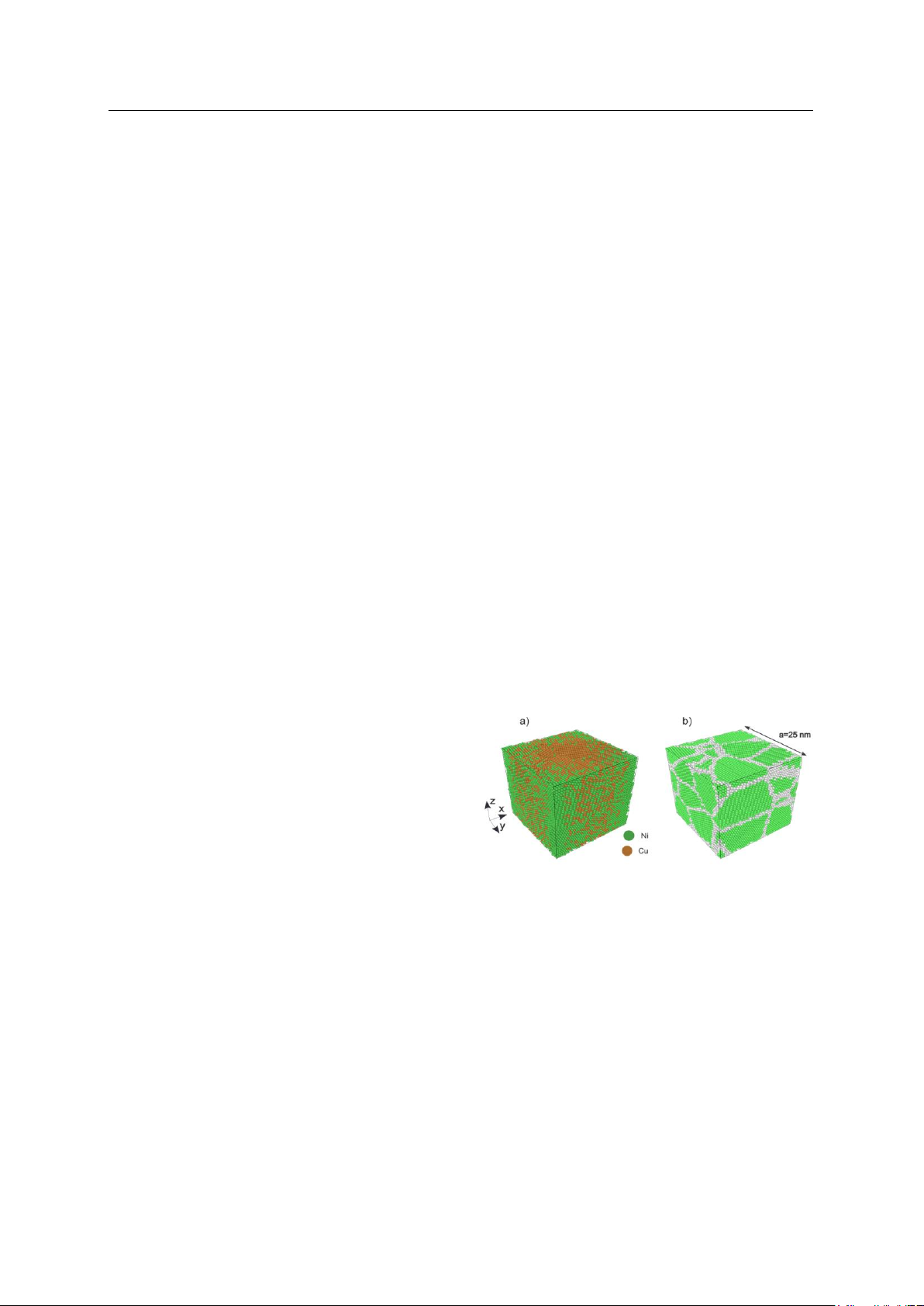
molecular dynamics (MD) simulations to investigate the tensile mechanical properties of CuNi CGNMs with
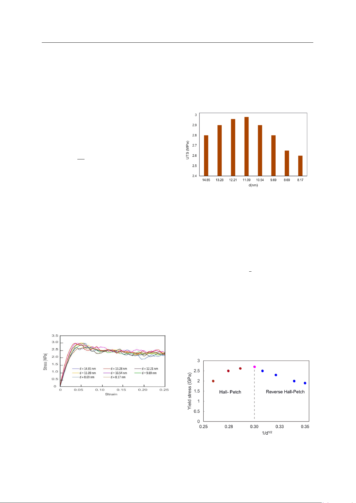
varying grain sizes. The findings demonstrate that the yielding stress of CGNMs increases with a decrease in
the grain sizes. Research shows that the critical value of the average grain diameter available to transform
the positive Hall-Petch relationship to an inverse one is dc equals 11.09 nm; at this size, the largest yield
strength (YS) is 2.7 GPa. This is explained as the average grain diameter has not reached the critical value,
the dislocations move during plastic deformation, and they accumulate at grain boundaries to form dislocation
clusters that prevent the further movement of other dislocations. This phenomenon causes the materials to
strengthen. When the grain size is smaller than the critical value, the grain volume is too small to contain
enough dislocations. Therefore, dislocations gliding across the boundary quickly reduce the YS, which means
materials soften due to the rotation or gliding of grain boundaries. This change in YS is consistent with the
inverse Hall-Petch relationship.
Keywords: Compositionally graded nanocrystalline materials, mechanical properties, grain size, molecular
dynamics simulation.
1. Introduction
1
Compositionally graded nanocrystalline
materials (CGNMs) are the most promising among
many advanced materials. They consist of two or more
elements where the composition continuously varies
along a dimension following a particular function [1].
Compositionally graded nanocrystalline materials are
conceived solutions to solve high-stress concentration,
high-temperature creep, and material delamination
challenges common in other fabricated materials such
as composites. These enhanced thermal and
mechanical properties render CGNMs a suitable
candidate for manufacturing structures of airplanes,
automobile engine components, and protective
coatings for turbine blades.
However, CGNMs also exhibit some distinct
properties compared to homogeneous metals and
alloys, such as mechanical properties that are not stable
in regions with variable composition. Especially, the
characteristics of CGNMs depend not only on their
compositions but also on the grain size. Based on this
characteristic, designing the CGNMs according to the
predetermined component will produce the material
with the desired mechanical properties. Therefore, a
ISSN 2734-9381
https://doi.org/10.51316/jst.181.etsd.2025.35.2.7
Received: Aug 30, 2024; revised: Oct 1, 2024
accepted: Oct 15, 2024
thorough explanation of the correlation between the
grain size of CGNMs and their mechanical properties
is essential and significant for the investigation,
design, and use of materials.
Two major approaches have been employed in
material fabrication: top-down and bottom-up.
Mechanical methods, such as rolling and forging, are a
top-down approach used primarily to change the
composition of the material's surface. This method
produces a multi-layer variable material with a
thickness of less than 10 nm per layer. Besides, the
second bottom-up approach includes chemical,
physical, electroplating, sputtering, laser firing, and
metal 3D printing techniques. These techniques allow
the production of thin films or sheets with thicknesses
greater than 10 nm up to several hundred nm. The laws
of composition and materials used when
manufacturing are diverse and follow the rules. Many
studies have been conducted to evaluate the
mechanical properties of CGNMs. Steel materials have
been successfully synthesized with variable
compositions, and it was observed that a decrease in
chemical stability and forming a ferrite layer in these
materials significantly increases the destructive
JST: Engineering and Technology for Sustainable Development
Volume 35, Issue 2, April 2025, 049-057
50
strength, increasing the material's toughness. It was
suggested that the component gradient in Fe-C steel,
made by partial decarbonization, can reduce the rate of
durable chemistry resulting in increased strength for
the material. Studies about the variable materials of
Mo/Al for an exponential symmetry sample with
different exponential values have concluded that the
strength of the material depends so much on the
exponential value. The internal crack position in
CGNMs relies on the direction of composition change.
Beyond empirical research, theoretical studies of
the CGNMs have also been conducted using the theory
of continuum environmental mechanics. In particular,
Karman's theory has been applied to analyze large
deformations of material plates that vary under
transverse forces [2]. Furthermore, the finite element
method has been used to study the deformation of
variable materials under the action of shear loads.
Another study has focused on the effect of radial loads
on the mechanical behavior of CGNMs. However,
these studies did not consider the effects of
microstructure, interactions between atoms,
dislocations, and planar defects on the mechanical
behavior of CGNMs at the nanoscale. Therefore, this
study must demonstrate the influence of all the above
factors on the mechanical properties and behavior of
CGNMs in atomic-level detail.
Recent studies have used molecular dynamics
(MD) simulations to clarify the mechanical behavior
of CGNMs, demonstrating that materials can change
mechanical properties by changing material
composition [3]. MD simulation proved to be a
suitable approach for studying the mechanical
properties of nanostructured CGNMs. However, some
important issues related to the mechanical behavior of
CGNMs remain unresolved, such as the mechanism
behind changes in the degree of deformation of
materials, the formation and development of
deviations, stacking errors, and the influence of
CGNMs at the nanoscale. Addressing these research
questions will continue to advance studies of the
mechanical properties of CGNMs.
The literature review does not provide any
published research on the influence of grain size on the
mechanical properties of CGNMs, so this research
could partly fill this gap. In this study, the mechanics
of CGNMs subjected to tension are investigated using
MD simulations. The effect of grain size on the
mechanical properties is investigated by considering
different grains that govern the composition
distribution profiles of CGNMs. Various mechanical
properties, including Young’s modulus (YM), yielding
stress (YS), and ultimate tensile strength (UTS), are
evaluated and compared among the different grain
sizes.
2. Method
2.1. Simulation Model
This study analyzes the mechanical properties
of CGNMs characterized by different grain
sizes through MD simulations. We selected
compositionally graded nanocrystalline materials of
Cu and Ni elements due to extraordinary immunity to
seawater corrosion. In particular, CuNi alloys are
resistant to chlorides in terms of pitting, cracking due
to stress corrosion, and even in hotter climates. Both
elements are widely used because of their exceptional
electronic, magnetic, and catalytic properties. Cu–Ni
alloy nanostructures reveal advantageous properties
such as good electronic conductivity, brilliant
magnetism, and favorable chemical stability, which
could find probable applications in nano-electronics.
Moreover, these alloys show high tensile,
compressive, and bending strength. They are also
commonly used for manufacturing various
components in the oil, marine, and chemical industries,
such as pumps, impellers, drill collars, valves, pipes,
and propeller shafts of marine and submarine engines
[4]. At below 1358K, at all alloying percentages,
Cu–Ni forms only a single Ξ±-phase and Ni atoms
supernumerary Cu atoms randomly from copper’s
FCC lattice points in Ξ±-phase. Several studies on the
properties of alloys and modified materials of these
two elements have been used by some authors to study
their mechanical properties [5]. Due to the reasons
above, we have chosen Ni and Cu as the alloying
constituents of CGNMs.
Fig. 1. Schematic illustration of CuNi CGNMs.
(a) Atomic rearrangements of CGNMs (b) Distribution
of grains, with white atoms are on the boundaries.
The cuboid simulation boxes are the same size
aΓ—aΓ—a = 25 nm Γ— 25 nm Γ— 25 nm as shown in Fig 1.
Each simulation box has a different number of grains.
Table 1 shows the average diameter of a grain d and its
roof square d.
Note that recent advances in nanomaterial
fabrication techniques have allowed us to create
nanowires with a diameter of about 5 nm. The
nanowire size used in the current study matches the
size that can be made experimentally [6].
JST: Engineering and Technology for Sustainable Development
Volume 35, Issue 2, April 2025, 049-057
51
Table 1. Grains information
Grain numbers(n)
d(nm)
1/ d1/2(nm)1/2
5
14.85
0.26
7
13.28
0.27
9
12.21
0.29
12
11.09
0.30
14
10.54
0.31
18
9.69
0.32
25
8.69
0.34
30
8.17
0.35
The Descartes coordinate system is used with the
crystal directions [100], [010] and [001] aligned along
the x, y, and z directions respectively. The {100}
system of the basal umbrella is similar to that found in
experimental studies. For example, different research
groups have successfully synthesized Cu-nanowires
with the {100}. Therefore, the CGNMs used in our
research have surfaces {100} closely resemble those
achieved in experiments. An important determinant of
the properties of compositionally graded
nanomaterials is the classification function. In the case
of CGNMs, the energy law function is mainly used.
This study uses energy law relationships to
govern the composition variation of CGNMs, in which
Cu and Ni atoms align themselves in a face-centered
cubic lattice (FCC) structure. The mathematical
expression for the change of Ni content in CGNMs is
indicated as [7]:
𝑔(π‘Ÿ)=(π‘Ÿ
𝑅)𝑝
(1)
where f is the mass fraction of the component Ni, and
p is the exponent of the gradient index. The
dependence of the Ni distribution on the gradient index
of CGNMs is illustrated with p = 1 made in this study.
The lattice constants of Cu (aCu) and Ni (aNi) at
0K are 3.6 Γ… and 3.52 Γ…, respectively, which induces
the lattice misfit between Cu and Ni of approximately
2.2%. We use an average lattice constant of the Cu and
Ni equals (aCu+ aNi)/2 is 3.56 Γ… to build CuNi CGNMs
models. This approach applies to CGNMs where the
lattice misfit between the constituents is moderate or
small, such as Cu-Ni, Ti-Al, and Ag-Au alloys [8]. The
process of constructing a CG-NW involves 3 steps.
Firstly, a pure Cu nanowires is generated with an FCC
structure and lattice constant of 3.56 Γ…. Secondly, the
Cu nanowires are divided into portions along the
z-direction, each with a length of 3.6. Finally, Cu
atoms within each portion are substituted by Ni atoms,
with the mass fraction determined by (1). Additionally,
the length of the CGNWs is significantly larger than
the length of each portion, resulting in a smooth
composition gradient that can be considered as a
continuous variation.
2.2. Interatomic Potential and Simulation Procedure
The embedded-atom method (EAM) potential is
employed to model the pairwise interactions of Cu and
Ni elements. This approach is commonly used for
metallic and intermetallic compounds. The total
energy of the system denoted as ETotal, comprising N
atoms, can be expressed as follows [9]:
𝐸Total =βˆ‘(𝐹𝑖(πœŒπ‘–)
𝑁
𝑖 = 1 +1
2βˆ‘πœ™π‘–π‘—(π‘Ÿπ‘–π‘—)
𝑗 β‰  𝑖
πœŒπ‘– = βˆ‘ πœŒπ‘–π‘—
π‘Ž(π‘Ÿπ‘–π‘—)
𝑗 β‰  𝑖
where Fi represents the embedding energy of atom i, ρi
corresponds to the electron density at site i, Ο•ij denotes
the pair potential function between atoms i and j, and
πœŒπ‘–π‘—
π‘Ž is the atomic charge density of atom j at the location
of atom i. MD simulations are performed using the
LAMMPS package [10]. Verlet's numerical
integration algorithm is applied to estimate the position
and velocity of atoms. A Nose-Hoover thermostat is
used to maintain a temperature of 300 K, while the
Berendsen barostat is employed to stabilize the
system's pressure at 0 bar. The time step is set to
0.001ps, the damping parameter is 0.1, and the drag
factors of the thermostat are adjusted to 1.0. After
conducting preliminary simulations and carefully
analyzing the behavior of total energy and atomic
oscillation, a relaxation time of 50 ps is selected.
Periodic boundary conditions are imposed in the
loading direction, while the simulation domain
boundaries in the x and y directions are non-periodic
and shrink-wrapped. Before the tensile test
simulations, a conjugate gradient minimization
scheme minimizes the system's energy. Afterward,
simulations are conducted using the NPT (fixed
number of particles (N), temperature (T), and pressure
(P) to achieve thermal equilibration. The NVE (fixed
number of particles (N), volume (V), and average
energy content (E) ensembles for a duration of 100 ps
were employed [11]. Once the CGNMs reach an
equilibrium state, a uniaxial strain along the z-direction
is applied to the CGNMs with a strain rate of 1010 s-1
and a maximum value of 30 %. This process allows for
the exploration of their mechanical behavior. In MD
simulations, strain rates ranging from 109 s-1 to
1010 s-1 are commonly employed to investigate the
mechanical properties of materials. We used a strain
rate of 1010 s-1 due to computational limitations in this
investigation.
JST: Engineering and Technology for Sustainable Development
Volume 35, Issue 2, April 2025, 049-057
52
2.3. Analysis Methods
Three analysis methods are used to identify the
microstructure evolution, including centrosymmetry
parameter (CSP) analysis, common neighbor analysis
(CNA), and dislocation extraction analysis (DXA).
The CSP analysis is different structures based on the
CSP, which measures the local lattice disorder around
an atom from a perfect lattice. The CNA is employed
for locating dislocation cores and also stacking faults
Finally, the DXA separates the crystal into good and
bad crystal regions using the common neighbor
analysis method. On the other hand, atomic-level stress
tensors are following equation:
πœŽπ›Όπ›½(𝑖) =βˆ’ 1
2Ξ©(βˆ‘πΉπ‘–π‘—
π›Όπ‘Ÿπ‘–π‘—
𝛽
𝑗 + 2𝑀𝑖𝑣𝑖𝛼𝑣𝑖𝛽 )
(4)
where Ξ± and Ξ² denote the Cartesian components; Ω is
the atomic volume; Fij is the force on atom i due to
atom j; Mi is the mass of atom i, and vi is the velocity
of atom i. The atomic arrangements and evolution of
microstructures are visualized and obtained with
OVITO software [12].
3. Results and Discussion
3.1. Mechanical Properties of Polycrystalline
Compositionally Graded Nanomaterials
Mechanical behaviors of CGNMs under uniaxial
tensile tests with different grain sizes are represented
in Fig. 2. The strain increases linearly with the stress
increase until a value of 4 % is reached. This shows
that with a small strain, there is no plastic deformation
in CGNMs, when the strain is larger than 0.02, the
stress-strain curves depart from each other. With a
strain greater than 4%, the stress increases nonlinearly
until it reaches the peak of stress (UTS) at a fracture
strain of 6%, and the stress sharply drops (strain
softening). The behavior of CGNMs is similar to
ductile materials of Ni or Cu.
Fig. 2. Stress-strain curves of CGNMs with different
grain sizes
To gain a deeper understanding of the mechanical
properties of CGNMs with various grain sizes, the
ultimate tensile strength (UTS) is considered first. The
UTS significantly depends on the grain sizes in Fig. 3.
It is obvious that the UTS increases with the decreasing
grain sizes if grain sizes are greater than 11.09 nm, it
considerately decreases when the grain sizes
considerably continue declining. In addition, the UTS
is the largest at d equals 11.09. The magnitude of UTS
covers a wide range from 2.6 GPa to 3.015 GPa as the
number of grains varies from 5 to 30. The range of
UTS magnitude is similar to results obtained from
different aluminum alloys [10].
Fig. 3. The ultimate tensile stress of CGNMs with
varying grain sizes.
The second important parameter is yield stress
(YS) which decides whether the CGNMs are plastic
deformation or only elastic behavior. The effect of
grain size on YS can be shown using the inverse square
root of grain diameter and the yield stress (YS),
Hall – Petch’s equation [13] determined the relation
between the YS and (d)1/2 following equation:
πœŽπ‘¦π‘ =𝜎0 +π‘˜π‘¦π‘‘βˆ’1
2 (πΊπ‘ƒπ‘Ž) (5)
where πœŽπ‘¦π‘  is the yield strength of the material, 𝜎0 is the
initial stress of the material, π‘˜π‘¦ is a constant related to
the crystal structure of the grain boundary, and d is the
average diameter of the grain.
Based on the simulation results, the yield limit of
materials with different grain sizes is determined.
Applying the Hall - Petch equation, the graph of the
relationship between yield stress and the square root of
grain size is constructed as shown in Fig. 4.
Fig. 4. Relation between yield stress and the inverse
square root grain diameter
JST: Engineering and Technology for Sustainable Development
Volume 35, Issue 2, April 2025, 049-057
53
It is obvious that when 1/d1/2 (nm)1/2 is smaller
than 0.3, the YS of material CGNMs follows the
Hall-Petch relation, if 1/d1/2 (nm)1/2 is greater than 0.3
the reverse Hall-Petch relation is compatible.
The Hall-Petch relation was explained by
slipping of dislocation. There is a limit to this mode of
strengthening, as infinitely strong materials do not
exist. When the grain size is large enough, the main
mechanism for deformation is the movement of
dislocation, where the grain boundary will restrict the
movement of dislocation. When grain size increases,
the distance between grain boundaries decreases,
hence the free mean path of dislocation decreases,
which increases the ultimate tensile strength. Grain
sizes might range from about 100 ΞΌm (large grains) to
1 ΞΌm (small grains). Lower than this, the size of
dislocations begins to approach the size of the grains.
At a grain size of about 10 nm, only one or two
dislocations can fit inside a grain. This scheme
prohibits dislocation pile-up and instead results
in grain boundary diffusion. The lattice resolves the
applied stress by grain boundary sliding, decreasing
the material's yield strength.
The grain size equals 11.09 nm, and the inverse
Hall–Petch was observed. This is because when the
grain size decreases at nm scale, there is an increase in
the density of grain boundary junctions which serves
as a source of crack growth or weak bonding. This is
due to a decrease in the stress concentration of grain
boundary junctions. These results are compatible with
Chen et al [14] who have researched the inverse
HallPetch relations of high-entropy alloys. In their
work, polycrystalline models of FCC-structured
CoNiFeAl0.3Cu0.7 with grain sizes ranging from 7.2 nm
to 18.8 nm were constructed to perform uniaxial
compression using molecular dynamic simulations.
All compression simulations were done after setting
the periodic boundary conditions across the three
orthogonal directions. It was found that when the grain
size is below 12.1 nm the inverse Hall–Petch relation
was observed. This is because as the grain size
decreases partial dislocations become less prominent
and so does deformation twinning. Instead, it was
observed that there is a change in the grain orientation
and migration of grain boundaries thus causing the
growth and shrinkage of neighboring grains. These are
the mechanisms for inverse Hall–Petch relations.
When the grain size is small enough, other
mechanisms for plastic deformation will occur, such as
grain boundary sliding. This new mechanism is
favorable when decreasing the grain size, which
explains the inverse Hall-Petch relation.
We can conclude that when decreasing grain size,
the material will first follow the Hall-Petch relation,
but then switch to the inverse Hall-Petch relation at a
grain diameter smaller than 11.09 nm.
3.2. Microstructure Evolution of Compositionally
Graded Nanowires
The mechanical behaviors of FCC materials have
indicated the presence of various planar defects during
tension, encompassing intrinsic stacking fault (ISF),
extrinsic stacking fault (ESF), twin boundary (TB),
and hexagonal close-packed (HCP) phase. The fraction
of intrinsic stacking fault (ISF), extrinsic stacking fault
(ESF), twin boundary (TB), and hexagonal
close-packed (HCP) phase are present in Fig. 5.
These planar defects have previously been
referred to as HCP structures. The formation of the
HCP phase in an FCC crystal was analyzed using CNA
first. However, there has been a lack of quantitative
consideration for the individual contributions of each
planar defect type in previous studies, despite their
significance in understanding the plastic mechanisms
of metallic materials.
Recently, S. Shuang et al. [15] introduced a novel
and robust planar defect analysis (PDA) algorithm to
classify various planar defects based on the nearest
neighbor structures. This classification approach
considers the coordinates of 12 atoms in the nearest
neighbor to discern the atomic structures and planar
defects. Additionally, the PDA compares the nearest
neighbor structure of coordinating atoms for defect
atoms with similar structural environments to capture
the differences and effectively characterize local
structures of planar defects. The PDA algorithm offers
a quantitative assessment of the evolution of planar
defects, thereby enhancing our understanding of the
dynamics of planar defects within the material. In this
study, we utilized the PDA algorithm to examine the
configuration of atomic evolution of CuNi CGNMs.
Fig. 5. Planar defect fraction of CuNi CGNMs with
12 grains.