
* Corresponding author.
E-mail addresses: srasaee@iust.ac.ir (S. Rasaee)
© 2014 Growing Science Ltd. All rights reserved.
doi: 10.5267/j.esm.2014.3.001
Engineering Solid Mechanics 2 (2014) 239-246
Contents lists available at GrowingScience
Engineering Solid Mechanics
homepage: www.GrowingScience.com/esm
Effect of transverse speed of the tool on microstructure and mechanical
properties in dissimilar butt friction stir welding of al5083–copper sheets
Y. Fotouhia, S. Rasaeea*, A. Askarib and H. Bisadia
aSchool of of Mechanical Engineering, Iran University of Science and Technology (IUST), Narmak, 16846-13114, Tehran, Iran
bDepartment of Engineering, Science and Research Branch, Islamic Azad University, Tehran, Iran
A R T I C L E I N F O A B S T R A C T
Article history:
Received September 20, 2013
Received in Revised form
October, 14, 2013
Accepted 27 February 2014
Available online
12 March 2014
In this paper, butt joining of Al5083 to commercially pure copper is investigated by friction stir
welding method. The effects of transverse welding speed of the tool on the mechanical
properties and microstructure of the joint were studied, experimentally. By examining different
circumstances, changes in the joint strength were studied and optimized in term of transverse
speed. Based on the obtained results, welding speed can improve or reduce the joint strength
and an optimum value can be found for the welding speed. Welded Joint that was conducted at
the rotation speed of 800 RPM and tool traverse speed of 60 mm min−1 had the highest tensile
strength (i.e. about 98% of the weak base metal). Intermetallic compounds were formed in the
stir zone and XRD results indicated that Al4Cu9 and Al2Cu were the intermetallic compounds in
the stir zone. Micro-cracks formed around the intimatelic particles were observed in the section
of joint.
© 2014 Growin
g
Science Ltd. All ri
g
hts reserved.
Keywords:
Friction stir welding
Dissimilar Al-Cu joint
Intermetallic compounds
Microstructure
Tensile strength
Transverse speed
1. Introduction
Friction stir welding (FSW) is a solid state joining process invented by Thomas and coworkers at
the Welding Institute (TWI) of UK in 1991 (Kiss & Czigány 2012). It is a perfect method to weld
materials that are hard to be joined by the conventional fusion welding methods such as high strength
aluminum alloys and magnesium. FSW which was used initially to connect high strength aluminum
alloys (olegrove & Shercliff, 2003; Sharma et al., 2012; Sutton et al., 2002) is nowadays used
frequently for joining many other alloys such as magnesium (Rajakumar et al., 2013), and steel
(Khodir et al., 2012). In recent years, the industrial demands have been widely increased for welding
and joining dissimilar materials with higher strength and good mechanical properties. Different

240
properties of the material and formation of brittle intermetallic compounds, which have low melting
ability, are the main concerns for obtaining a perfect joint using the conventional welding methods.
However, FSW as a solid state joining method is suitable technique for dissimilar materials. Most of
previous researches have focused on the welding of dissimilar aluminum alloys in a wide range of
thickness (Guo et al., 2014; Jonckheere et al., 2013). Copper and aluminum are widely used in
practical and engineering applications and hence high quality of weldments made from these
materials is an important problem. These materials are incompatible metals due to their higher
affinity at temperatures higher than 120°C and producing brittle intermetallics on the interfaces
(Ouyang et al., 2006). Copper-aluminum friction stir lap welding has been studied extensively to
investigate the mechanical properties of the joint (Abdollah-Zadeh et al., 2008; Bisadi et al., 2012,
Xue et al., 2011), microstructure evaluations (Bisadi et al., 2012; Firouzdor & Kou, 2012) and
intermetallic formation (Galvãoi et al., 2013; Xue et al., 2010). However, friction stir butt welding of
aluminum to copper has been rarely investigated due to the difficulties of performing these welds.
Previous researches have shown that many parameters such as tool rotation speed, welding speed
and offset of the tool can influence the quality of the dissimilar FSW joints. Until now, few studies
have been performed on dissimilar FSW copper-aluminum butt-joint (Xue et al., 2011; Fotoohi et al.,
2013; Galvão et al., 2012) and many aspects of the process are still unknown. In this paper, dissimilar
FSW of Al5083-copper butt-joints have been studied experimentally and the effect of welding speed
on the quality of welded joint is investigated. The aim of this study is to clarify the effect of this
parameter on the mechanical properties and the microstructure of butt dissimilar Al5083-copper FSW
joints.
2. Experimental procedures
Plates of Al5083 and commercially pure copper with thickness of 5 mm, length of 200 mm and
width of 100 mm were butt-welded in this study. The chemical composition and mechanical
properties of the used materials are given in Table 1. The edges and surfaces of the plates were
cleaned to remove the oxides and other pollutions. A vertical mill with automatic vertical and
horizontal movement ability was used in the process. Since, the location of aluminum and copper on
the advancing or retreating side can affect the quality of joint, the aluminum plate was located on the
advancing side in this research. The tool was rotated at a constant speed of 800 rpm during the
process. Control of the force during welding was not possible due to lack of required equipment and
only movement of tool was controlled. Welding process was performed using variable tool traverse
speeds in the range of 20-100 mm min−1. Table 2 presents the rotational and longitudinal speeds of
the FSW processes. Each experiment was repeated three times and the results are compared with each
other.
Table 1
Chemical and mechanical properties of work pieces
Tensile Strength
(MPa)
Hardness Al Ti Zn Cr Mg Mn Cu Fe Si
317 98 (Brinell) balance 0.1 0.2 0.2 4.5 0.5 0.1 0.4 0.4 5083 Al
224 45 (Vickers) - - - - - - > 99.5 - - Cu
Table 2
Parameters of FSW experiments
Test Number Rotational Speed Welding Speed
1 800 rpm 20 mm min−1
2 800 rpm 40 mm min−1
3 800 rpm 60 mm min−1
4 800 rpm 100 mm min−1

Y. Fotoohi et al. / Engineering Solid Mechanics 2 (2014)
241
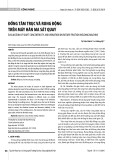
A cylindrical tool made of H13 steel and heat treated (to increase its strength and hardness) was
used. The diameter of tool shoulder was 20 mm with concavity of 6◦. In addition, the pin was simple
cylindrical and non-threaded having diameter and length of 5 mm and 4.7 mm, respectively. The tool
had 3◦ tilt angle for the better performing of the process. In order to prevent lateral movement and
bending of the plates during the welding a fixture was designed and manufactured. The fixture and
tool geometries are shown in Fig. 1 (a) and (b).
Fig 1. (a) The used fixture; (b) tool and schematic geometry of the used tool for FSW
After welding, a cross-section from each joint was prepared for metallographical analysis. The
Poulton's reagent solution was used for etching aluminum and another solution (60% H2O and 40%
HNO3) was used for copper. Then, optical microscope (OM) was used to observe the microstructure
of joints. Microstructure characterization and analyses were performed by scanning electron
microscopy (SEM), complemented by element distribution analysis maps, X-ray diffraction (XRD)
and energy dispersive spectroscopy (EDS). Some tensile tests were also performed to evaluate the
strength and mechanical properties of the joints. Tensile specimens according to ASTM-E8M were
cut from welded plate perpendicular to the weld line by using water jet such that the joint was in the
middle of the specimens. All the tensile tests were performed using SANTAM (STM250) machine
with a constant loading rate of 2 mm min-1 and for each sample, the maximum tensile load and the
position of failure was recorded and detected.
3. Results and discussion
The surface and cross-section of the welded specimens are shown in Fig. 2. At traverse speed of
20 mm min−1 the surface was rough and a large amount of flashes can be seen on the weld line
(especially on the aluminum side). The flashes were thick and almost had no sharp edges. The pasty
material which was pushed out of the weld zone is formed these flashes and coarse surface is formed
due to stock condition at the contact surface. By increasing the welding speed, the quality of surface
was improved and the amount of the flashes were reduced. The specimen manufactured at the
welding speed of 60 mm min−1 had the best surface quality and as it is seen from Fig. 2, at this
welding condition the surface is quite smooth and a little flash is only observed. for welding speeds
higher than 60 mm min−1 the quality of weld surface is decreased again. Lack of the proper flow of
material due to the low ductility is the possible reason for creation of rough surface at such high
welding speeds. For specimens welded at speed of 100 mm min−1 some particles like chips were
observed on the surface of weld showing these particles have been scraped from the surfaces of the
plates. Meanwhile at low speeds, the generated heat was not enough to soften the material. Thus for
these situations when the shoulder contacts with the workpiece surface, the process occurs similar to

242
the chip removal operations that can consequentely create rough surfaces.
There were some voids in the cross-section of the specimens welded with welding speed of 40 mm
min−1. The cross sections of the welded joints provide information about mixing the Al and Cu
materials. At low welding speeds, materials mix together almost uniform through the interface and it
is seen that more copper is entered to the aluminum side. However, by increasing the welding speed
mixing is performed under the influence of the shoulder at the upper side of the weld section and a
little mixing occurs at the weld root.
Fig. 2. Surface and cross-sections of the welded Al-Cu specimens
In the middle of cross section of the joint (called stir zone), materials are severely deformed by
the rotating motion of the pin and mechanically are mixed. Fig. 3 shows the SEM macroscopic
appearance of an Al–Cu joint. The dark area formed in the stir zone has clear contrast and different
structure and composition from the base materials and is full of particles. Based on the Al–Cu phase
diagram, aluminum and copper are incompatible and produce intermetallic components at
temperatures higher than 120◦C.Thus, due to rising temperature during the process, intermetallic
compounds are formed in the stir zone and in the interface. Hence, the dark area and particles inside
the stir zone can be mainly intermetallic compounds that formed during the process.
Fig. 3. SEM of the cross-section of the specimen conducted at the tool traverse speed of 40mm min-1
Element distribution analysis maps were performed to determine the composition of particles
spread in the stir zone and the corresponding results are shown in Fig. 4. The area shown in Fig. 4(a)
for the stir zone contains large bright particles in the dark matrix. Based on the map analysis results,
large bright particles are mainly composed of Cu surrounded by a matrix that mainly was aluminum.
Actually, copper particles are cut off from copper plate due to rotation and movement of pin and are
spread in aluminum matrix such that an area full of particles in the stir zone is formed.

Y. Fotoohi et al. / Engineering Solid Mechanics 2 (2014)
243
Fig. 4. Element distribution maps of the region in stir zone: (a) magnified view of aregion in stir
zone, (b) Al element and (c) Cu element (conducted at the tool traverse speed of 40mm min-1).
Magnified view of an area near the interface in the stir zone which located in box A in Fig. 3, is
shown in Fig. 5. In this area, three regions can be distinguished with different compositions, based on
the energy dispersive spectroscopy (EDS) analysis the bright area that is copper, light gray area that
mainly consists of aluminum and copper particles are distributed in it. Also in this Figure the dark
gray area with smaller particles (in comparison with the copper particles) show the intermetallic parts.
Fig. 5.The energy dispersive spectroscopy (EDS) results of the region in stir zone (located in Box A
in Fig. 3) of specimen number 2
To determine the intermetallic compounds that formed during the process, X-ray diffraction
analysis (XRD) was performed and XRD results are shown in Fig. 6. Except Mg, Al and Cu that had
obvious peaks, intermetallic compounds Cu9Al4 and CuAl2 were clearly identified. Carefull survey of
the morphological structures observed in the SEM images confirms the XRD results as well. By
observing the section of joints, it was cleared that the extent of the dark area formed in the stir zone
and the amount of particles distributed in the structure near the interface were decreased by increasing
the welding speed. Therefore, welding speed has an opposite effect on the formation of intermetallic
compounds.
Fig. 6. X-ray diffraction patterns of cross-section of Al-Cu joint of specimen number 2


![Thép cán kết cấu hàn: [Thông tin chi tiết/Báo giá/Hướng dẫn lựa chọn]](https://cdn.tailieu.vn/images/document/thumbnail/2020/20201014/maryland93/135x160/2381602661478.jpg)


![Giáo trình Cấu trúc dữ liệu và giải thuật - Trường CĐ Cơ điện Hà Nội [Mới nhất]](https://cdn.tailieu.vn/images/document/thumbnail/2026/20260323/lionelmessi01/135x160/58171774381670.jpg)


![Giáo trình Tiện nâng cao (Nghề Cắt gọt kim loại, Trình độ Cao đẳng) - Trường Cao đẳng Cơ điện Hà Nội [Mới nhất]](https://cdn.tailieu.vn/images/document/thumbnail/2026/20260323/lionelmessi01/135x160/48101774403543.jpg)


