ISSN: 2615-9740
JOURNAL OF TECHNICAL EDUCATION SCIENCE
Ho Chi Minh City University of Technology and Education
Website: https://jte.edu.vn
Email: jte@hcmute.edu.vn
JTE, Volume 19, Issue 06, 2024
95
Improved Controller for Interlinking Converter in Hybrid AC/DC Microgrids
Xuan Hoa Thi Pham , Hien-Thanh Le , Hai Van Tran*
Ho Chi Minh City University of Industry and Trade, Vietnam
*Corresponding author. Email: haitv@huit.edu.vn
ARTICLE INFO
ABSTRACT
14/11/2024
The AC/DC hybrid microgrids are a feasible solution to provide both AC
and DC power to electrical equipment. However, the control problem to
maintain voltage and frequency stability in AC/DC hybrid microgrids is
essential. This paper proposes a control method for the converter to
maintain voltage and frequency stability for AC/DC hybrid microgrids.
The power converter will operate bidirectionally to transfer power back
and forth between AC and DC subgrids in the AC/DC hybrid microgrid
operating in standalone mode. The proposed control method not only
controls the bidirectional power flow between AC and DC subgrids to
stabilize voltage and frequency as well as balance active power and reactive
power. In addition, the proposed method can restore voltage and frequency
for the microgrid in the event of sudden load surges or power failures in
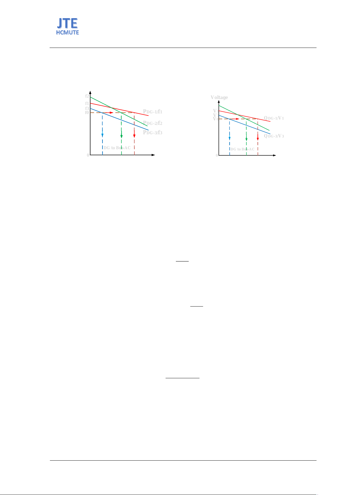
AC and DC subgrids. This method is established based on the relationship
between active power and frequency, because active power is present in
both AC and DC subgrids, while frequency is only present in AC subgrid.
However, in AC subgrid, frequency depends on active power, while in DC
subgrid, DC bus voltage depends on active power. Therefore, the proposed
method is designed based on adaptive frequency shifting to adjust the
power flow exchange between the two subgrids in order to maintain the
stability of the frequency and voltage of the buses. The suitability and
feasibility of the method are demonstrated by simulating the AC/DC hybrid
microgrid using Matlab/simulink software.
07/12/2024
20/12/2024
28/12/2024
KEYWORDS
Distributed energy resources;
Hybrid AC/DC microgrid;
Power control in microgrids;
Control of power converters;
Voltage and frequency control.
Doi: https://doi.org/10.54644/jte.2024.1719
Copyright © JTE. This is an open access article distributed under the terms and conditions of the Creative Commons Attribution-NonCommercial 4.0
International License which permits unrestricted use, distribution, and reproduction in any medium for non-commercial purpose, provided the original work is
properly cited.
1. Introduction
The issue of power control for power converters in microgrids has received significant attention in
research, with many studies both domestically and internationally developed to address this problem.
Currently, there are numerous research works on power control for AC microgrids or DC microgrids
[1]-[6]. These studies focus on power sharing among parallel-connected power converters to reduce
circulating currents in isolated microgrids, stabilizing frequency and voltage when the microgrid is
disconnected from the grid. Additionally, there are studies aimed at stabilizing the power flow into the
grid for grid-connected microgrids [7]-[10]; these studies have been conducted for purely AC or DC
microgrids and have not yet been applied to hybrid AC/DC microgrids. With the advantages of DC and
AC household appliances and devices, providing both AC and DC power for electrical devices, a hybrid
AC/DC microgrid appears to be a viable solution. Alternating current is typically available for electrical
devices. However, by using a hybrid AC/DC microgrid, DC power can be supplied to DC devices
without significant conversion losses. The power obtained from renewable sources such as photovoltaics
and fuel cells is in DC form. Therefore, it is necessary to integrate AC and DC microgrids through a
bidirectional power converter and establish a hybrid AC/DC microgrid, which helps alleviate power
sharing across different networks as well as both types of loads. Furthermore, it takes into account the
stability of the electrical system.
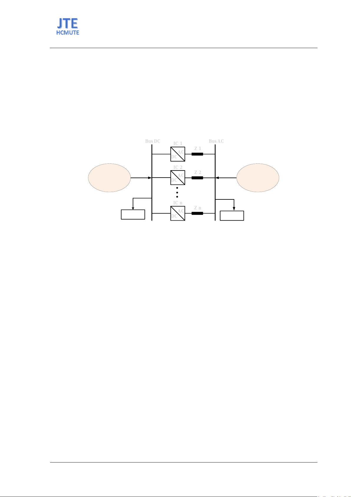
This paper proposes a power control method for a hybrid AC/DC microgrid containing supply
sources and loads structured as shown in Figure 1. This structure enhances the flexibility of power
distribution and utilizes distributed energy resources. The AC/DC converter, which manages the power
transfer between the AC and DC buses in the AC/DC microgrid, is referred to as the Interlinking
ISSN: 2615-9740
JOURNAL OF TECHNICAL EDUCATION SCIENCE
Ho Chi Minh City University of Technology and Education
Website: https://jte.edu.vn
Email: jte@hcmute.edu.vn
JTE, Volume 19, Issue 06, 2024
96
Converter (IC). The IC needs to manage the bidirectional power flow between the AC and DC
subnetworks, coordinating and controlling the power transfer between the AC and DC grids to maintain
the stability of the frequency and bus voltages for both AC and DC. This means that when a power
imbalance occurs in one subnetwork, the other networks will be affected, necessitating the provision of
essential support power to ensure electricity supply for all critical loads in the hybrid AC/DC microgrid
system.
The focus of this paper is on studying power control for Interlinking Converters (ICs) to maintain
stable voltage frequency on both AC and DC sides for a hybrid AC/DC microgrid in standalone mode,
as well as the balance of active and reactive power. The control method also enhancing the resilience of
the hybrid AC/DC microgrid during sudden load increases or power source failures in the AC and DC
subgrids.
DC
DCAC
AC
IC 1
IC 1 Z 1
Z 1
DC
DCAC
AC Z 2
Z 2
DC
DCAC
AC Z n
Z n
IC 2
IC 2
IC n
IC n
Bus DC
Bus DC Bus AC
Bus AC
DC load AC load
DC Subgrid AC Subgrid
Figure 1. Structure of AC/DC hybrid microgrid
2. Proposed controller
The simplified structure of the AC/DC microgrid is shown in Figure 1. It includes both AC and DC
subnetworks. The AC subnetwork consists of distributed generators (DG), alternating current loads,
nonlinear loads, and transmission lines. Similarly, the DC subnetwork includes direct current sources,
direct current loads, and transmission lines. The two buses, AC and DC, divide the entire microgrid
system into three parts: the AC grid, the DC grid, and the IC. The IC converter is controlled to ensure
that voltage and frequency remain stable under various operating conditions, linking both the AC and
DC subnetworks, and facilitating the bidirectional power flow. Due to sudden fluctuations in AC load,
the microgrid system exhibits a frequency drop. Likewise, significant changes in DC load result in a
voltage drop. These spontaneous changes in frequency and voltage are not only detrimental to the
performance of the microgrid system but also severely affect the lifespan of electrical equipment.
In standalone operating mode, without power from the grid, the IC needs to be controlled to maintain
a constant frequency and voltage at the AC and DC buses, thus a suitable control method needs to be
proposed. Figure 1 shows that the DC load is directly dependent on the consumer, and there may be
cases where the required DC load capacity exceeds the capacity of the DC sources. In this situation,
power transmission from the AC source to the DC side will be needed to compensate for the DC load
power demand. Similarly, in the case of an increase in AC load, if the AC load demand exceeds the AC
supply, it will also require power transmission from the DC source to the AC side to meet the demand.
Therefore, maintaining bus voltage stability and power balance is the control objective for the IC.
In this paper, we combine the P/f -Q/Vac droop control method and the P/Vdc droop control method
to manage bidirectional power for the inverter controller (IC) in different operating modes. The proposed
control strategy aims to enhance the stability of the microgrid and to address the power flow of the IC,
ensuring that the AC frequency and DC voltage of the microgrid remain within permissible limits. At
the same time, the proposed method also improves the resilience of the microgrid in the event of faults
in the AC and DC grid sources. The control scheme designed to meet these two objectives will be
presented in the following section.
ISSN: 2615-9740
JOURNAL OF TECHNICAL EDUCATION SCIENCE
Ho Chi Minh City University of Technology and Education
Website: https://jte.edu.vn
Email: jte@hcmute.edu.vn
JTE, Volume 19, Issue 06, 2024
97
2.1. Design of the droop control method for AC subgrid
Droop is a power control method that does not require communication [10]-[11]. The ability for
droop to operate without communication is essential for connecting remote power converters. It can
avoid complexity and high costs, enhancing the reliability of the system. Additionally, such a system is
easier to scale due to the plug-and-play features of the modules, allowing for the replacement of an
inverter without stopping the entire system. According to the droop principle, active power and reactive
power are controlled by two independent variables: frequency and voltage amplitude. Here, active power
controls by the system frequency, while reactive power controls by the voltage amplitude (droop P/f and
droop Q/V). This droop method has the advantages of being simple to implement, requiring no
communication, being flexible, and easily accommodating the expansion of microgrids.
The active and reactive power of distributed generators (DGs) in the AC subgrid in the Figure 1 is
calculated as follows [11]-[15]:
22
AC AC
V
P R V V cos XV sin
RX



(1)
22 AC AC
V
Q RV sin X V V cos
RX



(2)
In which: V is the output voltage of the distributed source in the AC subgrid, I is the current flowing
along the line connecting the distributed source to the common AC bus, δ is the phase angle difference
between the output voltage of the distributed source in the subgrid and the AC bus voltage, VAC is the
common AC bus voltage, and R and X are the impedance on the line.
In the distribution network, the line typically has X much larger than R, and the phase angle δ is
usually very small; thus, equations (1) and (2) can be rewritten as follows:
AC
XP
VV
(3)
AC XQ
VV V

(4)
Equations (3) and (4) show that the active power (P) depends on the frequency (f), and the reactive
power (Q) depends on the voltage (V). From this, we can establish the droop controller P/f and Q/V to
control the power for power converters as follows: Equations (3) and (4) show that the active power (P)
depends on the frequency (f), and the reactive power (Q) depends on the voltage (V). From this, we can
establish the droop controller P/f and Q/V to control the power for power converters as follows:
0p
f f m P
(5)
0q
V V m Q
(6)
The slope coefficients mp and mq are selected based on the allowable voltage deviation and
frequency compared to the nominal values.
00
;
min min
pq
max max
f f V V
mm
PQ


(7)
Pmax is the maximum active power that the distributed energy resource allows; Qmax is the maximum
reactive power that the distributed energy resource allows; P0 and Q0 are the rated active and reactive
power of the distributed energy resource; P and Q are the actual active and reactive power values that
the distributed energy resource generates; V0 and f0 are the rated voltage and rated frequency of the
microgrid system; V and f are the voltage and frequency at the output of the distributed energy resource.
ISSN: 2615-9740
JOURNAL OF TECHNICAL EDUCATION SCIENCE
Ho Chi Minh City University of Technology and Education
Website: https://jte.edu.vn
Email: jte@hcmute.edu.vn
JTE, Volume 19, Issue 06, 2024
98
Equations (5) and (6) are droop formulas for power control for DGs in the AC sub-grid, these DGs
have the same or different rated power, so droop equations (5) and (6) have different slope factors
determined by equation (7). According to research [4], the P/f droop curve in equation (5) for the DGs
is shown in figure 2a, the Q/V droop curve in equation (6) for the DGs is shown in figure 2b. The DGs
are connected in parallel so they have the same rated frequency f0 and rated voltage V0.
f1
f1
DG to Bus-AC
DG to Bus-AC
PDG-1/f1
PDG-1/f1
f2
f2
PDG-2/f2
PDG-2/f2
PDG-3/f3
PDG-3/f3
f3
f3
0
0 PDG-AC
f0
f0
PDG-1PDG-3 PDG-2
Voltage
Voltage
V1
V1
DG to Bus-AC
DG to Bus-AC
QDG-1/V1
QDG-1/V1
QDG-3/V3
QDG-3/V3
V3
V3
0
0
V0
V0
QDG-3 QDG-2 QDG-1
(a) (b)
Figure 2. Droop graph for AC subgrid, (a) Droop P/f, (b) Droop Q/V
2.2. Design of the droop control method for DC subgrid
The active power of the DGs in the DC subgrid in the Figure 1 is calculated as follows:
, dc DG dc dc dc
V i R V
(8)
In which: Vdc, DG is the output voltage of the distributed power source; Vdc is the common DC bus
voltage; Rdc is the resistance of the line connecting the distributed power source to the common DC bus,
and idc is the current flowing through the line. On the other hand, we have:
,
,
L dc
dc L dc
P
Vi
(9)
In which: PL,dc is the power consumption of the DC load; iL,dc is the current flowing through the DC
load. Combining (8) and (9) we have:
,
, ,
L dc
dc DG dc dc L dc
P
V i R i

(10)
From equation (10), the droop method for the DC microgrid can be implemented according to the
equation Pdc/Vdc:
0
dc dc dc dc
V V m P
(11)
In which mdc is the slope coefficient, calculated using the following formula:
0 ,
,
dc dc min
dc dc max
VV
mP
(12)
In which Pdc,max is the maximum active power that the distributed energy source is allowed to output
when the voltage on the DC bus drops to the minimum allowable voltage Vdc,min.
2.3. Design of the improved droop method for IC
Figure 1 shows that the DC load depends directly on the consumer, it may happen that the DC load
power required exceeds the power generated by the DC sources. In this situation, the transmission power
from the AC source side to the DC will be needed to compensate for the DC load power demand.
Similarly, in the case of an increased AC load, the AC load demand may exceed the AC supply, it also
ISSN: 2615-9740
JOURNAL OF TECHNICAL EDUCATION SCIENCE
Ho Chi Minh City University of Technology and Education
Website: https://jte.edu.vn
Email: jte@hcmute.edu.vn
JTE, Volume 19, Issue 06, 2024
99
requires transmission power from the DC sources side to the AC to meet the demand. Therefore,
maintaining stable bus voltage and power balance is the control goal for the IC. In addition, if the power
source in the AC or DC subgrid fails, the frequency and voltage at the buses will also drop sharply, the
sharp change in frequency and voltage will seriously affect the performance of the microgrid, affecting
the protection system and the life of the equipment in the microgrid. Therefore, improving the voltage
and frequency recovery ability when the power source fails is also the control goal for the IC. Equation
(5) is the droop P/f for the AC side, equation (11) is the droop P/Vdc for the DC side. These equations
show that P is present in both AC and DC sides. On the other hand, P is exchanged in both directions
by IC. When the AC side load increases or the AC source fails, the AC bus frequency and voltage will
decrease, at this time the AC side needs power support from the DC side to restore the AC bus frequency
and voltage. When the DC side load increases or the DC source fails, the DC bus voltage decreases, at
this time the DC side needs power support from the AC side to restore the DC bus voltage.
In this paper, the droop P/f and droop P/Vdc control methods are combined to control the
bidirectional power for ICs in different operating modes, which are responsible for linking the AC and
DC buses to operate automatically. The idea of the proposed control method is that each subgrid will
manage its own power flow. The surplus power will be distributed to other subgrids depending on the
power shortage or surplus of both subgrids. When the power flows from the AC side to the DC side, the
IC works as a parallel DC source, and the IC also works in the opposite direction when the power flows
from the DC side to the AC side. The frequency and voltage at the buses must be within the allowable
range. To unify the AC and DC grids, the frequency f in the alternating current grid and the voltage Vdc
in the direct current grid are standardized as follows:
/2
/2
max min
max min
f f f
fff


(13)
,,
,,
/2
/2
dc dc max dc min
dc max dc min
V V V
VVV


(14)
Combining f and V to generate the reference voltage for the IC output through the proposed
controller, they represent the quantity and direction of power flow between the AC and DC subgrids.
The frequency on the AC side will be balanced with the voltage on the DC side. Thus, any change in
the power level at any bus will affect the entire AC/DC microgrid, since the IC is the connecting element
between the two subgrids of the AC/DC microgrid. Therefore, controlling to achieve f = V can be
accomplished using a proportional-integral (PI) controller in the power controller for IC. Consequently,
IC is controlled as an alternating current voltage source with two-dimensional droop. To achieve
frequency and voltage stability in the AC/DC microgrid, a PI controller is used to shift the droop curve
along the axis f, ensuring that f and V are equal. Therefore, this paper proposes a method to improve
the equation droop P/f (5) by shifting the graph of equation (5) along the f axis as shown in Figure 3.
Figure 3 shows that when the load increases or the power source in the subgrids fails, the voltage and
frequency at the buses in the AC/DC microgrid are restored around the allowable value. The proposed
frequency shifting method as shown in Figure 3 can be written in the following equation:
0,
p ic ic p
f f m P k V f dt
(15)
0,q ic ic
V V m Q
(16)
The slope coefficients mp,ic and mq,ic are selected based on the allowable voltage deviation and
frequency compared to the nominal values.
,,
max min
p ic ic max
ff
mP
(17)