
7.4 Interrupt-Driven I/O
The problem with programmed I/O is that the processor has to wait a long time for the I/
O module of concern to be ready for either reception or transmission of data. The
processor, while waiting, must repeatedly interrogate the status of the I/O module. As e
result, the level of the performance of the entire system is severely degraded.
An alternative is for the processor to issue an I/O command to a module and then go on to
do some other useful work. The I/O module will then interrupt the processor to request
service when it is ready to exchange data with the processor. The processor then executes
the data transfer, as before, and then resumes its former processing.
Let us consider how this works, first from the point of view of the I/O module. For input,
the I/O module receives a READ command from the processor. The I/O module then
proceeds to read data in from an associated peripheral. Once the data are in the module’s
data register, the module signals an interrupt to the processor over a control line. The
module then waits until its data are requested by the processor. When the request is made,
the module places its data on the data bus and it then ready for another I/O operation.
From the processor’s point of view, the action for input is as follows. The processor
issues a READ command. It then goes off and does something else (e.g the processor
may be working on several different programs at the same time). At the end of each
instruction cycle, the processor checks for interrupts (Figure 3.9). When the interrupt
from the I/O module occurs, the processor saves the context (e.g.. Program counter and
processor registers) of the current program and processes the interrupt. In this case, the
processor reads the word of data from the I/O module and stores it in memory. It then
restores the context of the program it was working on (or some other program) and
resumes execution.
Figure 7.5b shows the use of interrupt I/O for reading in block of data. Compare this with
Figure 7.5a. Interrupt I/O is more efficient than programmed I/O because it eliminates
needless waiting. However, interrupt I/O still consumes a lot of processor time, because
every word of data that goes from memory to I/O module or from I/O module to memory
must pass through the processor.
Interrupt Processing
Let us consider the role of the processor in interrupt-driven I/O in more detail. The
occurrence of an interrupt triggers a number of events, both in the processor hardware
and in software. Figure 7.7 shows a typical sequence. When an I/O device completes an I/
O operation, the following sequence of hardware events occurs:
1. The device issues an interrupt signal to the processor.
2. The processor finishes execution of the current instruction before responding to the
interrupt, as indicated in Figure 3.9
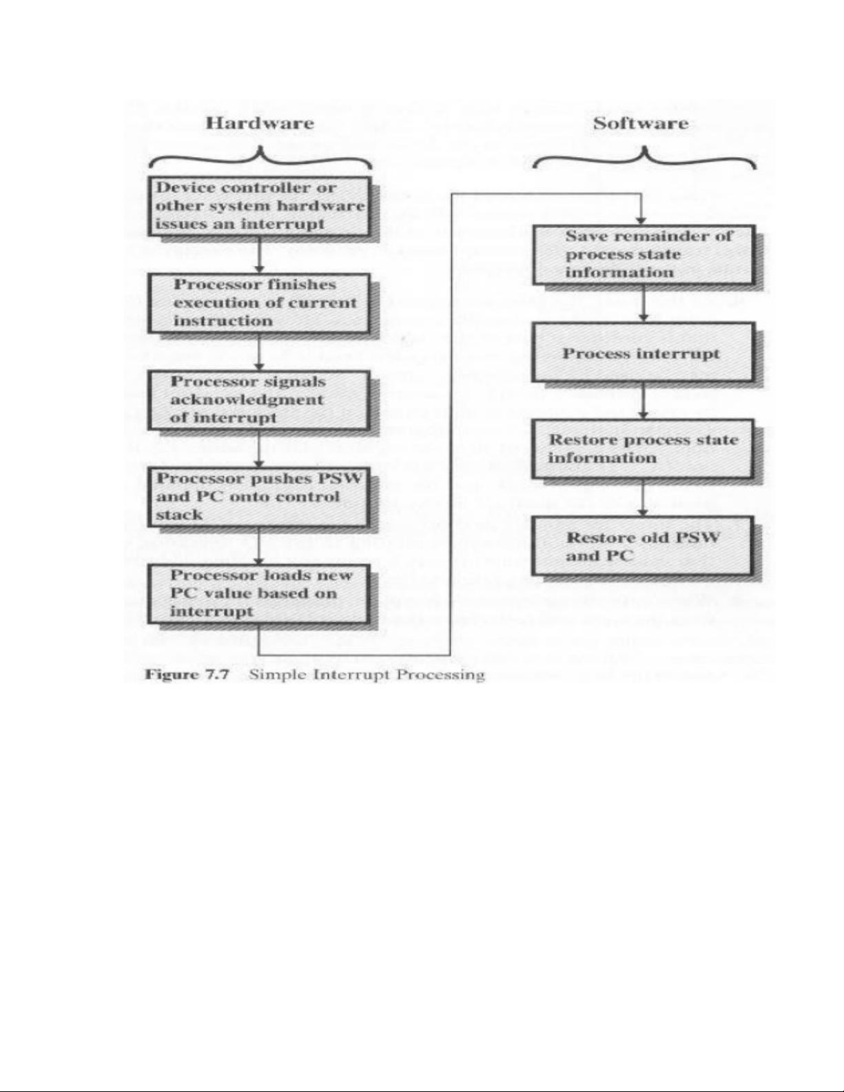
3. The processor tests for an interrupt, determines that there is one, and sends an
acknowledgment signal to the device that issued the interrupt. The acknowledgment
allows the devices to remove its interrupt signal.
4. The processor now needs to prepare to transfer control to the interrupt routine. To
begin, it needs to save information needed to resume the current program at the point of
interrupt. The minimum information required is (a) the status of the processor, which is
contained in a register called the program status word (PSW), and (b) the location of the
next instruction to be executed, which is contained in the program counter. These can be
pushed onto the system control stack.
5. The processor now loads the program counter with the entry location of the interrupt-
handling program that will respond to this interrupt. Depending on the computer
architecture and operating system design, there may be a single program, one program for
each type of interrupt, or one program for each device and each type of interrupt. If there
is more than one interrupt-handling routine, the processor must determine which one to
invoke. This information may have been included in the original interrupt signal, or the

processor may have to issue a request to the device that issued the interrupt to get a
response that contains the needed information.
Once the program counter has been loaded, the processor proceeds to the next instruction
cycle, which begins with an instruction fetch. Because the instruction fetch is determined
by the contents of the program counter, the result is that control is transferred to the
interrupt-handler program. The execution of this program results in the following
operations:
6. At this point, the program counter and PSW relating to the interrupted program have
been saved on the system stack. However, there is other information that is considered
part of the “state” of the executing program. In particular, the contents of the processor
registers need to be saved, because these register may be used by the interrupt handler.
So, all of there values, plus any other state information, need to be saved. Typically, the
interrupt handler will begin by saving the contents of all registers on the stack. Figure
7.8a shows a simple example. In this case, a user program is interrupt after the instruction
at location N. The contents of all of the registers plus the address of the next instruction
(N+1) are pushed onto the stack. The stack pointer is updated to point to the new top of
stack, and the program counter is updated to point to the beginning of the interrupt
service routine.
7. The interrupt handler next processes the interrupt. This includes an examination of
status information relating to the I/O operation or other event that caused an interrupt. It
may also involve sending additional commands or acknowledgments to the I/O device.
8. When interrupt processing is complete, the saved register values are retrieved from the
stack and restored to the registers (e.g see Figure 7.8b)
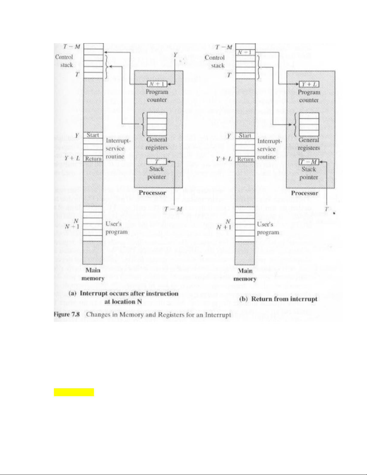
9. The final act is to restore the PSW and program counter values from the stack. As a
result, the next instruction to be executed will be from the previously interrupt program.
Note that it is important to save all the state information about the interrupted program
for later resumption. This is because the interrupt is not a routine called from the
program. Rather, the interrupt can occur at any time and therefore at any point in the
execution of a user program. Its occurrence is unpredictable. Indeed, as we will see in the
next chapter, the two programs may not have anything in common and may belong to two
different users.
Design Issues
Two design issues arise in implementing interrupt I/O. First, because there will almost
invariably be multiple I/O modules, how does the processor determine which device
issued the interrupt? And second, if multiple interrupt have occurred, how does the
processor decide which one to process?

Let us consider device identification first. Four general categories of techniques are in
common use:
-Multiple interrupt lines
-Software poll
-Daisy chain (hardware poll, vectored)
-Bus arbitration (vectored)
The most straightforward approach to the problem is to provide multiple interrupt lines
between the processor and the I/O modules. However, it is impractical to dedicate more
than a few bus lines or processor pins to interrupt lines. Consequently, even if multiple
lines are used, it is likely that each line will have multiple I/O module attached to it.
Thus, one of the other three techniques must be used on each line.
One alternative is the software poll. When processor detects an interrupt, it branches to an
interrupt-service routine whose job it is to poll each I/O module to determine which
module caused the interrupt. The poll could be in the form of a separate command line
(e.g Test I/O). In this case, the processor raises TESTI/O module responds positively if it
set the interrupt. Alternatively, each I/O module could contain an addressable status
register. The processor then reads the status register of each I/O module to identify the
interrupting module. Once the correct module is identified, the processor branches to a
device-service routine specific to that device.
The disadvantage of the software poll is that it is time consuming. A more efficient
technique is to use a daisy chain, which provides, in effect, a hardware poll. An I/O
modules share a common interrupt request line. The interrupt acknowledge line is daisy
chained through the modules. When the processor senses an interrupt, it sends out an
interrupt acknowledge. This signal propagates through a series of I/O module until it gets
to a requesting module. The requesting module typically responds by placing a word on
the data lines. This word is referred to as a vector and is either the address of the I/O
module or some other unique identifier. In either case, the processor uses the vector as a
pointer to the appropriate device-service routine. This avoids the need to execute a
general interrupt-service routine first. This technique is called a vectored interrupt.
There is another technique that makes use of vectored interrupt, and that is bus
arbitration. With bus arbitration, an I/O module must first gain control of the bus before it
can raise the interrupt request line. Thus, only one module can raise the line at a time.
When the processor detects the interrupt, it responds on the interrupt acknowledge line.
The requesting module then places its vector on the data lines.
The aforementioned techniques serve to identify the requesting I/O module. They also
provide a way of assigning priorities when more than one device is requesting interrupt
service. With multiple lines, the processor just picks the interrupt line with the highest
priority. With software polling, the order in which modules are polled determines their
priority. Similarly, the order of modules on a daisy chain determines their priority.
Finally, bus arbitration can employ a priority scheme, as discussed in Section 3.4
We now turn to two examples of interrupt structures.
Intel 82C59A Interrupt Controller
The Intel 80386 provides a single Interrupt Request (INTR) and a single Interrupt
Acknowledge (INTA) line. To allow the 80386 to handle a variety of devices and priority
structures, it is usually configured with an external interrupt arbiter, the 82C59A.
External devices are connected to the 82C59A, which in turn connects to the 80386.


![Ngân hàng đề thi trắc nghiệm Kiến trúc máy tính [mới nhất]](https://cdn.tailieu.vn/images/document/thumbnail/2026/20260514/hoahongxanh0906/135x160/49281779160279.jpg)


%20--%3e%3cdefs%3e%3cstyle%3e%20.st0%20{%20fill:%20%23fff;%20}%20.st1%20{%20fill:%20%237800fa;%20}%20%3c/style%3e%3c/defs%3e%3cpath%20class='st1'%20d='M117.78,12.18H43.11c2.9,3.47,4.65,7.94,4.65,12.82,0,5.6-2.3,10.66-6.01,14.29h76.02l7.22-13.56-7.22-13.56Z'/%3e%3cg%3e%3cpath%20class='st0'%20d='M53.58,26.17h-.59v-1.46h.59v-4.96h2.83c1.78,0,2.67.94,2.67,2.82v5.76c0,1.87-.89,2.81-2.67,2.81h-2.83v-4.96ZM55.36,21.37v3.34h1.1v1.46h-1.1v3.34h1.01c.61,0,.91-.37.91-1.1v-5.93c0-.74-.3-1.1-.91-1.1h-1.01Z'/%3e%3cpath%20class='st0'%20d='M65.99,31.14h-1.8l-.31-2.07h-2.19l-.31,2.07h-1.64l1.82-11.39h2.62l1.82,11.39ZM65.28,18.04c-.25.46-.51.77-.75.94-.21.15-.47.22-.79.22-.26,0-.57-.07-.92-.22l-.38-.15c-.14-.05-.26-.07-.37-.07-.3,0-.53.18-.71.54l-.91-.68c.25-.46.51-.77.75-.94.21-.14.48-.21.79-.21.26,0,.57.07.92.21l.38.15c.14.05.26.07.37.07.3,0,.53-.18.71-.54l.91.68ZM61.91,27.52h1.73l-.87-5.76-.87,5.76Z'/%3e%3cpath%20class='st0'%20d='M74.53,26.89v1.52c0,1.91-.89,2.86-2.67,2.86s-2.67-.95-2.67-2.86v-5.93c0-1.91.89-2.86,2.67-2.86s2.67.95,2.67,2.86v1.11h-1.69v-1.22c0-.75-.31-1.12-.93-1.12s-.93.37-.93,1.12v6.15c0,.74.31,1.11.93,1.11s.93-.37.93-1.11v-1.63h1.69Z'/%3e%3cpath%20class='st0'%20d='M81.4,31.14h-1.8l-.31-2.07h-2.19l-.31,2.07h-1.64l1.82-11.39h2.62l1.82,11.39ZM75.9,19.2l1.52-1.91h1.71l1.51,1.91h-1.61l-.76-.95-.75.95h-1.61ZM77.32,27.52h1.73l-.87-5.76-.87,5.76ZM83.1,15.99l-1.76,1.91h-1.26l1.17-1.91h1.86Z'/%3e%3cpath%20class='st0'%20d='M84.86,19.75c1.78,0,2.67.94,2.67,2.82v1.48c0,1.87-.89,2.81-2.67,2.81h-.85v4.28h-1.79v-11.39h2.64ZM84.01,21.37v3.86h.85c.58,0,.87-.36.87-1.08v-1.71c0-.71-.29-1.07-.87-1.07h-.85Z'/%3e%3cpath%20class='st0'%20d='M93.51,19.75c1.78,0,2.67.94,2.67,2.82v1.48c0,1.87-.89,2.81-2.67,2.81h-.85v4.28h-1.79v-11.39h2.64ZM92.66,21.37v3.86h.85c.58,0,.87-.36.87-1.08v-1.71c0-.71-.29-1.07-.87-1.07h-.85Z'/%3e%3cpath%20class='st0'%20d='M98.8,31.14h-1.79v-11.39h1.79v4.88h2.03v-4.88h1.83v11.39h-1.83v-4.88h-2.03v4.88Z'/%3e%3cpath%20class='st0'%20d='M105.36,24.55h2.46v1.62h-2.46v3.34h3.09v1.63h-4.88v-11.39h4.88v1.63h-3.09v3.18ZM108.17,17.29l-1.76,1.91h-1.26l1.17-1.91h1.86Z'/%3e%3cpath%20class='st0'%20d='M112.2,19.75c1.78,0,2.67.94,2.67,2.82v1.48c0,1.87-.89,2.81-2.67,2.81h-.85v4.28h-1.79v-11.39h2.64ZM111.35,21.37v3.86h.85c.58,0,.87-.36.87-1.08v-1.71c0-.71-.29-1.07-.87-1.07h-.85Z'/%3e%3c/g%3e%3ccircle%20class='st1'%20cx='25'%20cy='25'%20r='20'/%3e%3cpath%20class='st0'%20d='M32.78,19.27c2.92,0,4.43,2.55,5.28,5.33l.71,2.17c.14.38-.33.75-.71.75h-5.61c.19-.33.24-.71.09-1.08l-.75-2.45c-.43-1.32-.99-2.64-1.79-3.77.75-.57,1.65-.94,2.78-.94h0ZM25,18.38c3.25,0,4.9,2.78,5.89,5.89l.76,2.45c.14.42-.33.8-.8.8h-11.69c-.42,0-.94-.38-.8-.8l.75-2.45c.99-3.11,2.64-5.89,5.89-5.89h0ZM25,11.35c1.74,0,3.11,1.37,3.11,3.11s-1.37,3.11-3.11,3.11-3.11-1.41-3.11-3.11,1.41-3.11,3.11-3.11h0ZM17.27,19.27c1.08,0,1.98.38,2.73.94-.8,1.13-1.37,2.45-1.74,3.77l-.8,2.45c-.14.38-.05.75.09,1.08h-5.56c-.42,0-.9-.38-.75-.75l.71-2.17c.9-2.78,2.41-5.33,5.33-5.33h0ZM17.27,12.91c1.51,0,2.78,1.27,2.78,2.83s-1.27,2.83-2.78,2.83-2.83-1.27-2.83-2.83,1.27-2.83,2.83-2.83h0ZM32.78,12.91c1.56,0,2.78,1.27,2.78,2.83s-1.23,2.83-2.78,2.83-2.83-1.27-2.83-2.83,1.27-2.83,2.83-2.83h0ZM27.07,28.56v.09c0,.57-.24,1.08-.61,1.46h0v.05c-.38.33-.9.57-1.46.57s-1.08-.24-1.46-.61h0c-.38-.38-.61-.9-.61-1.46v-.09h1.41v.09c0,.19.05.38.19.47v.05c.09.09.28.19.47.19s.38-.09.47-.19v-.05c.14-.09.24-.28.24-.47t-.05-.09h1.41ZM30.99,28.56v.09c0,1.65-.66,3.16-1.74,4.24-1.08,1.08-2.59,1.79-4.24,1.79s-3.16-.71-4.24-1.79l-.05-.05c-1.04-1.08-1.7-2.55-1.7-4.2v-.09h1.41v.09c0,1.27.47,2.4,1.27,3.25h.05c.85.85,1.98,1.37,3.25,1.37s2.4-.52,3.25-1.37c.85-.8,1.37-1.98,1.37-3.25v-.09h1.37ZM34.99,28.56v.09c0,2.78-1.13,5.28-2.92,7.07-1.79,1.79-4.29,2.92-7.07,2.92s-5.23-1.13-7.07-2.92c-1.79-1.79-2.92-4.29-2.92-7.07v-.09h1.41v.09c0,2.4.94,4.53,2.5,6.08,1.56,1.56,3.72,2.5,6.08,2.5s4.52-.94,6.08-2.5c1.56-1.56,2.5-3.68,2.5-6.08v-.09h1.41Z'/%3e%3c/svg%3e)