REGULAR ARTICLE
Iron-chrome-aluminum alloy cladding for increasing safety in
nuclear power plants
Raul B. Rebak
*
GE Global Research, 1 Research Circle, Schenectady, NewYork 12309, USA
Received: 10 June 2017 / Received in nal form: 25 September 2017 / Accepted: 7 November 2017
Abstract. After a tsunami caused plant black out at Fukushima, followed by hydrogen explosions, the US
Department of Energy partnered with fuel vendors to study safer alternatives to the current UO
2
-zirconium
alloy system. This accident tolerant fuel alternative should better tolerate loss of cooling in the core for a
considerably longer time while maintaining or improving the fuel performance during normal operation
conditions. General electric, Oak ridge national laboratory, and their partners are proposing to replace
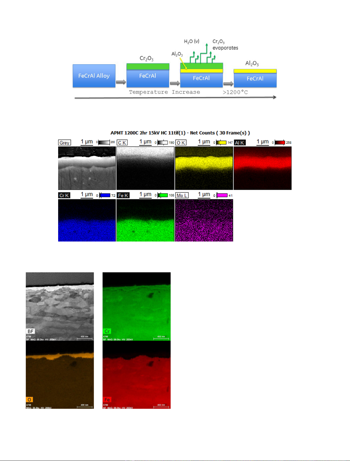
zirconium alloy cladding in current commercial light water power reactors with an iron-chromium-aluminum
(FeCrAl) cladding such as APMT or C26M. Extensive testing and evaluation is being conducted to determine
the suitability of FeCrAl under normal operation conditions and under severe accident conditions. Results show
that FeCrAl has excellent corrosion resistance under normal operation conditions and FeCrAl is several orders of
magnitude more resistant than zirconium alloys to degradation by superheated steam under accident conditions,
generating less heat of oxidation and lower amount of combustible hydrogen gas. Higher neutron absorption and
tritium release effects can be minimized by design changes. The implementation of FeCrAl cladding is a near
term solution to enhance the safety of the current eet of commercial light water power reactors.
1 Introduction
Nuclear power plants are one of the most reliable and
cleaner ways of producing electricity. Approximately 450
commercial nuclear power plants are used in 30 countries
to produce low cost electricity [1]. At least 13 countries
use nuclear power to supply about a quarter of their
electricity [2]. In the USA alone, the use of nuclear power
prevented in 2015 the release of 564 million metric tons of
carbon dioxide to the environment [2]. Commercial
nuclear power plants (NPP) are designed to be operated
without signicant effect on the public health and safety
and effect on the environment [3]. The operation of NPP
energy facilities do not emit greenhouse gases [2]. The
main risk of operating a nuclear power plant is the release
of radioactive elements into the environment, and for
that reason, several barriers are constructed between the
fuel containing the radioactive elements and the
environment. The rst barrier to protect the fuel is the
hermetically sealed metallic cladding which envelops the
pellets of uranium oxide. That is, maintaining the
integrity of the cladding is the rst crucial containment
for the radioactive material. Further barriers include the
reactor pressure vessel, the concrete building structure
containing the pressure vessel and abundant amounts of
water that remove the heat from the nuclear reaction [3].
The Nuclear regulatory commission of the USA uses
probabilistic risk assessment methods to assess the likelihood
and consequences of severe reactor accidents in accordance
with the code of federal regulations 10 CFR 50.109 [3]. The
Risk R is dened as a function of scenarios Si that can go
wrong, of how likely the scenario will happen (frequency ),
and of the consequence Ci of the scenario, Si (Eq. (1)) [4].
R¼fSi;fi;Cig:ð1Þ
The notion of risk includes both opportunities and
threats. The basis of managing risk is to build multiple
barriers between the threats that can lead to an adverse
event of, for example, an operating a nuclear reactor. In the
case of the Fukushima disaster of March 2011, the low
frequency and high consequence event of the tsunami
caused the destruction of the diesel generators that
provided the emergency power to pump the water to cool
the fuel rods in the reactor and in the cooling pools.
Consequently, water and steam reacted rapidly with the
zirconium material of the fuel cladding above 400 °C
producing large amounts of heat and hydrogen (Eq. (2))
that were vehicles for the release of some radioactivity into
the environment.
*e-mail: rebak@ge.com
EPJ Nuclear Sci. Technol. 3, 34 (2017)
©R.B. Rebak, published by EDP Sciences, 2017
DOI: 10.1051/epjn/2017029
Nuclear
Sciences
& Technologies
Available online at:
https://www.epj-n.org
This is an Open Access article distributed under the terms of the Creative Commons Attribution License (http://creativecommons.org/licenses/by/4.0),
which permits unrestricted use, distribution, and reproduction in any medium, provided the original work is properly cited.
Zr þ2H2O¼ZrO2þH2þHeat:ð2Þ
Once the zirconium metal cladding was consumed by
steam, the radioactive fuel was released inside the second
barrier, the thick-walled steel reactor pressure vessel. That
is, the effect of the tsunami in Fukushima was to destroy
the rst barrier or the metallic zirconium cladding
containing the radioactive elements. To minimize the risk
of failure of the operating nuclear power plant, a stronger
rst barrier should be constructed between the fuel and the
second barrier, and eventually from the environment.
2 Risk management in a nuclear power plant
environment
Benets from risk management in a nuclear power plant do
not only include safety scenarios but also production
(operational or engineering) and economics (nancial)
scenarios [5](Fig. 1). Each one of these risk disciplines will
incorporate their own frequencies and consequences.
Another discipline or scenario that can be added is the
strategic one, which covers things like type of government
in the country, nationalization or expropriations, public
perception, regulatory and legal framework, etc. (repre-
sented as the larger square in Fig. 1). It is important to
identify all the consequences of an event (e.g. tsunami) to
be able to minimize adversarial outcomes and to maximize
public response and commercial gains in a cost-efcient
manner [5]. The risk management framework is an iterative
process in which rst the possible risks are identied
(together with potential consequences and relative impact
of each consequence), then the techniques to manage the
risk are identied (e.g. risk reduction or risk transfer), and
nally the chosen strategies or techniques are imple-
mented. This process is followed by monitoring and
feedback to determine the effectiveness of the solutions
and, if necessary, repeat the process with other improved
measures. For example, risk reduction can be accomplished
by engineering changes, organizational changes, staff
training, etc. and risk transfer can be implemented by
contracts with suppliers, insurance, regulation, etc.
Following the example from the Fukushima incident,
one way of reducing risk in plant operation would be the
engineering replacement of zirconium alloys from the
nuclear fuel of the power plant with FeCrAl alloys. This is
an obvious technical change that would greatly reduce the
consequence of the explosion that considerably affected the
public perception of safe operation of nuclear power plants.
That is, the use of FeCrAl alloys can only produce
opportunities to reduce the engineering risk identied in
Figure 1. The FeCrAl alloy is the rst barrier between the
radioactive elements and the biosphere surrounding the
NPP. By improving on the performance of the rst barrier
(cladding of the fuel), the consequence of combustible
hydrogen explosion or release of radioactive elements
outside the NPP is greatly minimized.
3 Accident tolerant fuels (ATF)
Because of the Fukushima accident of March 2011, the US
Department of Energy (DOE) has a mandate from US
Congress to develop accident tolerant fuels under cost
sharing programs with the nuclear fuel vendors [68].
Today many prefer to call the Accident tolerant fuel (ATF)
as Advanced technology fuel (ATF). A fuel may be dened
as having enhanced accident tolerance if, in comparison
with the current UO
2
-zirconium alloy system, it can
tolerate loss of active light water cooling in the reactor core
for a considerably longer time (called coping time) while
maintaining or improving fuel performance during normal
operations and operational transients, as well as in design
basis and beyond design-basis events. The enhanced fuel
material should have
improved reaction kinetics with steam;
slower hydrogen production rate;
improved cladding and fuel properties;
enhanced retention of ssion products.
The DOE provided a ve-step guideline or metrics to
assess the behavior of the ATF concept (Fig. 2)[9]. That is,
the concept for accident tolerant fuel rods must be able to
perform as well as the current system under normal
operation conditions in the order of 300400 °C cladding
temperature (Step 1). This includes low corrosion rates in
both boiling water reactors (BWR) and pressurized water
reactor (PWR) environments, no environmental assisted
cracking, no shadow corrosion, no hydriding that will
render the rod brittle, no fretting or debris damage, etc.
(Step 1). Also in Step 1, it needs to be demonstrated that
the new fuel will be compatible with the thermal and
hydraulic ow inside of the reactor. Step 2 requires that the
ATF fuel rod would be better than the current zirconium
uranium dioxide system under design basis accidents
including the temperature range between 400 and 1200 °C
Fig. 1. Risk management environment model for a nuclear
power plant operator. The aim of the GE-ORNL team is to
minimize engineering risks by using FeCrAl cladding.
2 R.B. Rebak: EPJ Nuclear Sci. Technol. 3, 34 (2017)
of the cladding temperature in contact with the coolant.
Step 3 requires that under severe accident conditions
(T>1200 °C), the cladding would be superior to the
current system, for example by tolerating reaction with
steam to produce lower amounts of heat and explosive
hydrogen gas [10]. Step 4 requires that the new ATF fuel
rod can be manufactured easily using economical and
standard procedures such as tube fabrication and hermeti-
cal welding or sealing. Moreover, Step 4 covers the changes
that are required in the regulators or licensing specica-
tions (e.g. Nuclear regulatory commission in the US) that
would allow for the new ATF rod to be deployed into a
commercial light water reactor. Step 5 is concerned about
the condition of the fuel rods after their useful life in the
reactor, if the bundles can be safely and integrally removed
from the reactor to be securely stored in cooling pools for a
period of 5 years or more, and how the rods will perform
under dry cask storage for periods in the order of 100 years,
before nal disposition in a nuclear waste repository or
reprocessing of the used fuel [9].
The objective of the GE project is to develop an iron-
chromium-aluminum (FeCrAl) fuel cladding for current
design light water power reactors. The idea of using FeCrAl
alloys as cladding for current UO
2
fuel is also supported by
Oak ridge national laboratory (ORNL), who developed the
alloy C26M. Besides Fe, Cr, and Al, the cladding may
contain other elements such as molybdenum, yttrium,
hafnium, zirconium, etc. The composition of choice is
Fe + (1022) Cr + (46) Al + (23) Mo + traces of Y, Hf,
Zr, etc. The FeCrAl cladding concept is a near term
solution for providing enhanced safety to the current eet
of light water reactors. The main reason FeCrAl has been
selected is because it has superior oxidation resistance in
the event of a severe accident. Figure 3 shows the process of
how this alloy resists attack by superheated steam. Under
normal operation conditions and up to 1000 °C the
protection to the alloy is given by the formation of a
chromium rich oxide on the surface. However, as the
temperature increases beyond 1000 °C, an aluminum oxide
layer (alumina) forms between the metal and the
chromium oxide layer. Eventually, in the presence of
steam, the chromium oxide layer volatilizes and the
alumina layer remains on the surface protecting the alloy
from further oxidation up to its melting point (1500 °C).
Figure 4 shows the presence of a one micron thick layer of
alumina on the surface of APMT coupon after exposure for
2 h at 1200 °C in 100% steam.
FeCrAl has excellent environmental resistance charac-
teristics under normal operation both for boiling and
pressurized water reactors (BWR and PWR) coolants.
There is no need to change the water chemistry of the BWR
and PWR light water coolants since FeCrAl is compatible
with the existing water chemistries. The use of FeCrAl
would eliminate common/current fuel failure mechanisms
such as fretting and shadow corrosion. There is no change
in fuel type since the GE FeCrAl concept utilizes the
present UO
2
fuel. The current FeCrAl alloy candidates are
APMT and C26M, the latter being an optimization alloy
composition with lower Cr to avoid embrittlement under
irradiation. Fabrication studies continue at ORNL and
GE. ORNL and GE have been conducting research in the
ve areas listed in Figure 2 since 2012. The aim of this
document is to describe the maturity of the FeCrAl concept
and the overall feasibility on the use of ferritic FeCrAl
alloys as cladding for nuclear fuel in commercial light water
reactors. GE and ORNL are following a methodical
approach to evaluate metrics or performance attributes
outlined by Bragg-Sitton et al. [9]. Many other countries
such as China, Japan, Korea, Belgium, etc. are also
developing ATF fuel based on FeCrAl.
It is noted that austenitic stainless steel (SS) materials
were used for fuel rod cladding in the past both for US
commercial plants and overseas NPP [11]. Preliminary
studies on FeCrAl alloy materials indicate sufcient
strength and ductility to perform acceptably as cladding
alloy, like past use of austenitic SS cladding. FeCrAl alloys
do not contain nickel, which is a more expensive and a
higher neutron absorption element than Fe, Cr or Al.
However, compared to the negative experience with
austenitic SS cladding, extensive crack propagation studies
in high temperature water showed that ferritic FeCrAl was
several orders of magnitude more resistance to environ-
mentally-assisted cracking than modern type 304 SS [7].
Because of its ferritic or bcc structure, FeCrAl alloys are
also more resistant to irradiation degradation than prior
versions of austenitic SS cladding materials. Proton
irradiation studies performed at the U. of Michigan showed
that FeCrAl materials may be resistant to proton
irradiation induced cracking providing additional conr-
mation of the potential acceptability of FeCrAl materials
for fuel rod cladding [12]. Although there may be nominal
changes in fuel rod geometry (e.g. clad OD and thickness)
for lead rod assembly designs and in fuel assembly designs
(e.g. fuel channels design) to accommodate differences in
material performance in future fuel designs, such changes
are expected to be incremental to existing fuel rod and
assembly designs, signicantly leveraging the knowledge
base for current fuel designs for the new concept.
Simulation studies performed at Brookhaven National
Laboratory showed that there is little or no impact on the
thermal-hydraulic properties of the system by using a fuel
rod clad with a FeCrAl alloy [13]. It is expected that a
FeCrAl alloy clad fuel rod can be designed with minimal
Fig. 2. Five metric Areas Provided by DOE to Evaluate ATF [9].
R.B. Rebak: EPJ Nuclear Sci. Technol. 3, 34 (2017) 3
thermal-hydraulic design changes. FeCrAl alloy cladding is
completely compatible with the current coolant chemis-
tries used in either BWR or PWR reactors, that is,
signicant coolant chemistry changes are not expected
because of FeCrAl implementation. Extensive immersion
studies with chemistries typically observed in both BWR
and PWR reactors showed excellent corrosion resistance of
the FeCrAl alloys both under hydrogen and oxygen
atmospheres [14,15]. Figure 5 shows a protective Cr rich
layer protecting the surface of APMT while exposed for a
year in PWR type environments containing dissolved
hydrogen. This is the same behavior observed for other
current structural reactor internal materials such as type
316 SS [16,17].
Electrochemical studies in high temperature water
showed that FeCrAl have a behavior like traditional
reactor alloys such as type 304 SS and nickel based alloy X-
750. Electrochemical studies performed at GE Global
Research showed that FeCrAl rods in contact with a
separator grid of alloy X-750 would not experience galvanic
corrosion under irradiation conditions [18], allowing
utilization of current existing grid/spacer designs.
Japan and other countries are also participating in the
development of FeCrAl alloys for fuel cladding [19,20].
Fig. 4. Coupon of APMT exposed to 100% steam for 2 h at 1200 °C. A 1 mm-thick alumina layer is observed on it surface.
Fig. 5. Coupon of APMT exposed to PWR type water pure
water + 3.75 ppm hydrogen at 330 °C for one year. A 150 nm
oxide layer rich in Cr is observed on its surface.
Fig. 3. Oxidation Behavior of FeCrAl in Super-Heated Steam.
4 R.B. Rebak: EPJ Nuclear Sci. Technol. 3, 34 (2017)
4 Fabrication, manufacturing and licensing
The FeCrAl/UO
2
fuel rod is compatible with current
large-scale production technology. Uranium dioxide
(UO
2
) pellet fabrication would remain the same as in
the current process. Currently, tube fabrication trials are
being conducted to demonstrate that FeCrAl alloys can be
produced as long, thin walled tubes for fuel rod
assemblies. Although the cladding fabrication process is
yet untested for large scale production, there does not
appear to be a signicant barrier for production quantities
of the cladding. Preliminary studies demonstrated
FeCrAl compatibility with existing welding, manufactur-
ing, and quality practices used with current Zircaloy
based rod assembly systems. The fabrication processes for
the FeCrAl/UO
2
system will be similar to the current
LWR fuel fabrication processes (pilgering/extruding,
heat treatments, welding, NDE techniques, etc.) which
are mature and well understood. Figure 6 shows etched
metallographic cross sections of APMT and C26M tubes
made following industrial practices. Figure 7 shows initial
welding trials at the industrial fuel plant of APMT thin
wall tubes to the APMT end caps. No issues were
encountered complying with current nuclear industry
quality and performance standards.
FeCrAl/UO
2
fuel rod systems will have minimal or no
impact in the handling of the fuel, shipping requirements
and/or plant operations. It is expected that standard
analyses techniques applied to zirconium alloy systems
may be used substituting FeCrAl-specic properties to
demonstrate acceptable performance under shipping and
handling conditions, although licensing for shipping of the
LFR/LFAs will need to be completed as well as in-core
licensing.
Originally the deadline for insertion of a LFA into a
commercial reactor given by DOE was 2022 [9]buttheGE
team working with the US Nuclear regulatory commission
and Southern nuclear is planning to have a rst FeCrAl
installation in a commercial nuclear reactor in the Spring
of 2018 [21]. For this rst installation, tube segments of
APMT (a powder metallurgy alloy) and C26M (a
traditionally melted experimental alloy) will be used.
The main differences between these two alloys is their Cr
content and the method of fabrication.
5 Mitigation measures to neutron absorption
and tritium release
By its own nature, FeCrAl alloys offer a larger parasitic
neutron absorption compared to zirconium alloys [6,7,22].
Because FeCrAl alloys such as APMT and C26M are
stronger than zirconium alloys at near 400 °C, the FeCrAl
material for the cladding can be made approximately half
the thickness of the current zirconium alloys (Figs. 68).
The thinning of the wall will increase the volume of the
uranium dioxide pellet inside the rod.
Additional design changes (such as the fuel channel),
may be required to meet bundle design requirements,
further impacting fuel cycle economics. However, poten-
tial mitigation strategies have been identied that may
partially or fully offset these neutron penalties. Such
mitigation strategies include alternate materials (e.g.
silicon carbide composite channel materials), higher
allowable heat generation rates, as well as relaxation of
regulatory requirements due to much improved fuel
cladding performance under normal/off-normal, design
basis and beyond design basis accident conditions, which
in turn will result in improved economics of plant
operation.
A second issue that requires resolution is the potential
to increase release of tritium into the coolant. EPRI
reported that when austenitic stainless steel cladding was
used for power generation the amount of tritium in the
coolant water was approximately 10 times higher than
when zirconium cladding was used [23]. Also since FeCrAl
are ferritic (bcc) in nature, it can be inferred that the
diffusion of tritium through the cladding wall into the
Fig. 6. Thin walled tubes of APMT and C26M fabricated using industrial practices. APMT is Fe + 21Cr + 5Al + 3Mo and C26M is
Fe + 12Cr + 6Al + 2Mo.
R.B. Rebak: EPJ Nuclear Sci. Technol. 3, 34 (2017) 5