Chapter 7 Timing generation and measurements
7.1 Timer functions
• Stop watch. • Captures time of external events. • Creates output waveform. • Pulse accumulations. • Creates periodic interrupts.
Microcomputer principles and applications
7.1 Timer functions
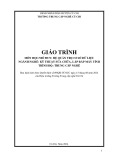
Triangle
Sine
Ramp up
Ramp down
Square
Pulse
Microcomputer principles and applications
7.2 MSP430 Timer
• Asynchronous 16-bit timer/counter with four operating modes. • Selectable and configurable clock source. • Two or three configurable capture/compare registers. • Configurable outputs with PWM capability. • Asynchronous input and output latching. •
Interrupt vector register for fast decoding of all Timer A interrupts.
Microcomputer principles and applications
7.3 Timer A
Generally MSP430 family contains two categories of timers
• Timer A • Timer B.
What is the difference between Timer A and Timer B?
Same in operation, but Timer B is more sophisticated than Timer A and it has many features available than compared with Timer A. They are:
• Bit-length of the timer is programmable as 8-bit, 10- bit, 12-bit,
16-bit.
• Some Timers in B category have 7 CCR registers whereas the
Timer A contains three capture/compare registers. It contains double-buffered CCR register.
• • CCR register can be grouped.
Microcomputer principles and applications
7.3 Timer A
How many timers are there in MSP430G2553?
There are two 16-bit timers are available in MSP430G2553, excluding watch dog timer.
• Timer A0. • Timer A1.
Each 16-bit timer starts counts from 0 to 0x0FFFF (0 to 65536) and they operate in four different modes:
• Stop mode - Timer is in halt state or stops the timer. • Up mode - Timer counts up from zero to value stored in
TACCR0 register (other than 0xFFFF) and roll over to zero after it reached the count value. Generally this mode used to produce time delays.
Microcomputer principles and applications
7.3 Timer A
• Continuous mode - it is same as UP mode but here Timer
counts up from zero to maximum value 0xFFFFh and rolls over to zero after it reached 0xFFFF and keep going.
• Up/Down mode- in this mode time counts up from 0 to TACCR0 register and then counts down back to zero as shown in figure. It is good for generating PWM’s and driving motors.
Microcomputer principles and applications
7.3 Timer A
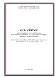
0FFFFh
TACCR0
Up mode
0FFFFh
TACCR0
Continous mode
0FFFFh
TACCR0
Up/Down mode
Microcomputer principles and applications
7.3 Timer A
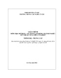
Timer clock
TASSELx
IDx
MCx
15
0
16-bit timer TAR
EQU0
Divider 1/2/4/8
Count mode
RC
Clear
TACLK ACLK SMCLK INCLK
Set TAIFG
00 01 10 11
TACLR
CCR0
CCR1
CCR2
Microcomputer principles and applications
7.3 Timer A
• CCR0, CCR1, CCR2 (Compare/Capture Registers) are used to
load the timer count.
• TAR (Timer A Register) is the 16-bit timer register in which the
count start increment/decrements value depends upon the timer mode settings.
• CCIFG interrupt flag is set when the timer counts to the value
stored in CCR0 register.
• TAIFG interrupt flag is set when the timer count from CCR0 to
zero.
• TASSELx are the bits used to select one of the clock signals. • IDx bit are used to divide the clock signal applied to timer. • MCx bits are used select count mode. • TACLR bit clears the TAR register, clock divider and count
direction (mode).
Microcomputer principles and applications
7.4 Timer A Output modes
OUTMODE.x Mode Output 000
001
Set
Description The output signal OUTx is defined by the OUTx bit. The OUTx signal updates im- mediately when OUTx is updated. The output is set when the timer counts to the TACCRx value. It remains set until a reset of the timer, or until another output mode is selected and affects the output.
010
Toggle/Reset The output
011
Set/Reset
is toggled when the timer counts to the TACCRx value. It is reset when the timer counts to the TACCR0 value. The output is set when the timer counts to the TACCRx value. It is reset when the timer counts to the TACCR0 value.
Microcomputer principles and applications
7.4 Timer A Output modes
OUTMODE.x Mode Toggle 100
101
Reset
110
Toggle/Set
111
Reset/Set
Description is toggled when the timer The output counts to the TACCRx value. The output period is double the timer period. The output is reset when the timer counts to the TACCRx value. It remains reset un- til another output mode is selected and af- fects the output. is toggled when the timer The output counts to the TACCRx value. It is set when the timer counts to the TACCR0 value. The output is reset when the timer counts to the TACCRx value. It is set when the timer counts to the TACCR0 value.
Microcomputer principles and applications
7.4 Timer A Output modes
Example: Timer in Up Mode
0FFFFh TACCR0
TACCR1
Output mode 1: Set
Output mode 2: Toggle/Reset
Output mode 3: Set/Reset
Output mode 4: Toggle
Output mode 5: Reset
Output mode 6: Toggle/Set
Output mode 7: Reset/Set
EQU1
EQU1
EQU0 TAIFG
EQU0 TAIFG
EQU0 TAIFG
Interrupt events
Microcomputer principles and applications
7.5 Timer A interrupts
There are two interrupt flags (CCIFG and TAIFG) and its corresponding two interrupt vectors (TACCR0 and TAIV) available for Timers in MSP430.
Microcomputer principles and applications
7.5 Timer A interrupts
Timer block
TAIFG
Interrupt vectors
CCR0
CCIFG
TACCR0
CCR1
CCIFG
TAIV
CCR2
CCIFG
Microcomputer principles and applications
7.6 Timer A registers
TACTL - Timer A Control Register
15 14 13 12 11 10 9 8
Unused
TASSELx
rw-(0) rw-(0) rw-(0) rw-(0) rw-(0) rw-(0) rw-(0) rw-(0)
7 6 5 4 3 2 1 0
MCx
IDx
MCx
rw-(0) rw-(0) rw-(0) rw-(0)
Unused rw-(0)
TACLR rw-(0)
TAIE rw-(0)
TAIFG rw-(0)
Bits 15-10 Unused Unused
Timer_A clock source select TASSELx Bits 9-8
00 TACLK
01 ACLK
10 SMCLK
11 INCLK
Microcomputer principles and applications
(INCLK is device-specific and is often assigned to the inverted TBCLK) (see the device-specific data sheet)
7.6 Timer A registers
TACTL - Timer A Control Register
15
14
13
12
11
10
9
8
Unused
TASSELx
rw-(0)
rw-(0)
rw-(0)
rw-(0)
rw-(0)
rw-(0)
rw-(0)
rw-(0)
7
6
5
4
3
2
1
0
MCx
IDx
MCx
rw-(0)
rw-(0)
rw-(0)
rw-(0)
Unused rw-(0)
TACLR rw-(0)
TAIE rw-(0)
TAIFG rw-(0)
IDx
Bits 7-6
Input divider. These bits select the divider for the input clock
/1
00
/2
01
/4
10
/8
11
MCx
Bits 5-4
Mode control. Setting MCx = 00h when Timer_A is not in use conserves power.
Stop mode: the timer is halted.
00
Up mode: the timer counts up to TACCR0.
01
Continuous mode: the timer counts up to 0FFFFh.
10
Up/down mode: the timer counts up to TACCR0 then down to 0000h.
11
Microcomputer principles and applications
7.6 Timer A registers
TACTL - Timer A Control Register
15 14 13 12 11 10 9 8
Unused
TASSELx
rw-(0) rw-(0) rw-(0) rw-(0) rw-(0) rw-(0) rw-(0) rw-(0)
7 6 5 4 3 2 1 0
MCx
IDx
MCx
rw-(0) rw-(0) rw-(0) rw-(0)
Unused rw-(0)
TACLR rw-(0)
TAIE rw-(0)
TAIFG rw-(0)
Unused Bit 3 Unused
TACLR Bit 2
Timer_A clear. Setting this bit resets TAR, the clock divider, and the count direction. The TACLR bit is automatically reset and is always read as zero. Timer_A interrupt enable. This bit enables the TAIFG interrupt request . TAIE Bit 1
0 1 Interrupt disabled Interrupt enabled
Timer_A interrupt flag. Bit 0 TAIFG
Microcomputer principles and applications
0 1 No interrupt pending Interrupt pending
7.6 Timer A registers
TAR - Timer A Register
15
14
13
12
11
10
9
8
TARx
rw-(0)
rw-(0)
rw-(0)
rw-(0)
rw-(0)
rw-(0)
rw-(0)
rw-(0)
7
6
5
4
3
2
1
0
TARx
rw-(0)
rw-(0)
rw-(0)
rw-(0)
rw-(0)
rw-(0)
rw-(0)
rw-(0)
Bits 15-0
Timer_A register. The TAR register is the count of Timer _A.
TARx
Microcomputer principles and applications
7.6 Timer A registers
TACCRx - Timer A Capture/Compare Register
15
14
13
12
11
10
9
8
TARx
rw-(0)
rw-(0)
rw-(0)
rw-(0)
rw-(0)
rw-(0)
rw-(0)
rw-(0)
7
6
5
4
3
2
1
0
TARx
rw-(0)
rw-(0)
rw-(0)
rw-(0)
rw-(0)
rw-(0)
rw-(0)
rw-(0)
Bits 15-0
TACCRx
Timer_A capture/compare register. Compare mode: TACCRx holds the data for the comparison to the timer value in the Timer_A Register, TAR. Capture mode: The Timer_A Register, TAR, is copied into the TACCRx register when a capture isperformed .
Microcomputer principles and applications
7.6 Timer A registers
TACCTLx - Timer A Capture/Compare Control Register
15
14
13
12
CMx
CCISx
11 SCS
10 SCCI
9 Unused
8 CAP
rw-(0)
rw-(0)
rw-(0)
rw-(0)
rw-(0)
r
r0
rw-(0)
7
6
5
4
3
2
1
0
CCIFG
rw-(0)
OUTMODx rw-(0)
rw-(0)
CCIE rw-(0)
CCI r
OUT rw-(0)
COV rw-(0)
rw-(0)
Capture mode
CMx
Bits 15-14
No capture Capture on rising edge
00 01
Capture on fallig edge Capture on both rising and falling edges
10 11
CCISx
Bits 13-12
Capture/compare input select. These bits select the TACCRx input signal. See the device-specific data sheet for specific signal connections.
00 01
CCIxA CCIxA
GND Vcc
10 11
Bit 11
SCS
Synchronize capture source. This bit is used to synchronize the capture input signal with the timer clock. 0 1
Asynchronous capture Synchronous capture
Microcomputer principles and applications
7.6 Timer A registers
TACCTLx - Timer A Capture/Compare Control Register
15
14
13
12
CMx
CCISx
11 SCS
10 SCCI
9 Unused
8 CAP
rw-(0)
rw-(0)
rw-(0)
rw-(0)
rw-(0)
r
r0
rw-(0)
7
6
5
4
3
2
1
0
CCIFG
rw-(0)
OUTMODx rw-(0)
rw-(0)
CCIE rw-(0)
CCI r
OUT rw-(0)
COV rw-(0)
rw-(0)
SCCI
Bit 10
Unused
Bit 9
Synchronized capture/compare input. The selected CCI input signal is latched with the EQUx signal and can be read via this bit Unused. Read only. Always read as 0.
SCS
Bit 8
Compare mode Capture mode
TACLR
Bits 7 - 5
OUT bit value Set Toggle/reset Set/reset Toggle Reset Toggle/set Reset/set
Capture mode 0 1 Output mode. Modes 2, 3, 6, and 7 are not useful for TACCR0, because EQUx = EQU0. 000 001 010 011 100 101 110 111
Microcomputer principles and applications
7.6 Timer A registers
TACCTLx - Timer A Capture/Compare Control Register
15
14
13
12
CMx
CCISx
11 SCS
10 SCCI
9 Unused
8 CAP
rw-(0)
rw-(0)
rw-(0)
rw-(0)
rw-(0)
r
r0
rw-(0)
7
6
5
4
3
2
1
0
CCIFG
rw-(0)
OUTMODx rw-(0)
rw-(0)
CCIE rw-(0)
CCI r
OUT rw-(0)
COV rw-(0)
rw-(0)
CCIE
Bit 4
Capture/compare interrupt enable. This bit enables the interrupt request of the corresponding CCIFG flag.
0 1
Interrupt disabled Interrupt enabled
CCI
Bit 3
Capture/compare input. The selected input signal can be read by this bit.
OUT
Bit 2
Output. For output mode 0, this bit directly controls the state of the output . 0 1
Output low Output high
COV
Bit 1
Capture overflow. This bit indicates a capture overflow occurred. COV must be reset with software. 0 1
No capture overflow occurred Capture overflow occurred
CCIFG
Bit 0
Capture/compare interrupt flag 0 1
No interrupt pending Interrupt pending
Microcomputer principles and applications
7.6 Timer A registers
TAIV - Timer A Interrupt Vector Register
10 0
8 0
14 0 r0
13 0 r0
9 0 r0
15 0 r0
12 0 r0
11 0 r0
r0
r0
1
7
3
2 TAIVx
0 0
6 0 r0
0 r0
5 0 r0
4 0 r0
r-(0)
r-(0)
r-(0)
r0
Interrupt Source
Interrupt flag
TAIV contents
Interrupt priority
00h 02h 04h 06h 08h 0Ah 0Ch 0Eh
No interrupt pending Capture/Compare Capture/Compare Reserved Reserved Timer overflow Reserved Reserved
- TACCR1 CCIFG TACCR2 CCIFG - - TAIFG - -
Highest - - - - - - Lowest
Microcomputer principles and applications


![Bài giảng Tổ chức - Cấu trúc Máy tính II Đại học Công nghệ Thông tin (2022) [Mới Nhất]](https://cdn.tailieu.vn/images/document/thumbnail/2025/20250515/hoatrongguong03/135x160/8531747304537.jpg)