
REGULAR ARTICLE
Preliminary proliferation study of the molten salt fast reactor
Michel Allibert
1
, Elsa Merle
1,*
, Sylvie Delpech
2
, Delphine Gerardin
1
, Daniel Heuer
1
, Axel Laureau
1
,
and Simon Moreau
1
1
CNRS/IN2P3/LPSC UGA –Grenoble INP, Grenoble, France
2
CNRS/IN2P3/IPN Orsay, Orsay, France
Received: 15 March 2019 / Received in final form: 17 September 2019 / Accepted: 12 December 2019
Abstract. The molten salt reactor designs, where fissile and fertile materials are dissolved in molten salts, under
consideration in the framework of the Generation IV International Forum, present some unusual characteristics
in terms of design, operation, safety and also proliferation resistance issues. This paper has the main objective of
presenting some proliferation challenges for the reference version of the Molten Salt Fast Reactor (MSFR), a
large power reactor based on the thorium fuel cycle. Preliminary studies of proliferation resistance are presented
here, dedicated to the threat of nuclear material diversion in the MSFR, considering both the reactor system
itself and the processing units located onsite.
1 Introduction
The Generation IV International Forum (GIF) [1] has
proposed a methodology that should allow the analysis of
proliferation resistance and physical protection (PR&PP)
issues in advanced nuclear reactors under development. An
initial application of this methodology to the MSFR [2]is
presented here, including an analysis of both the reactor
and the fuel processing units, these being located in situ in
this concept. For this initial study, we have focused our
attention on a portion of the methodology retained by GIF
and restricted our study to what is specific of this reactor
concept.
Because the MSFR is in the design phase, we have
adopted a gradual approach of the issues, focusing on the
seemingly most critical situations. The idea is to carry out
many partial analyses on topics such as Safety and
Proliferation Resistance (PR), to define constraints that
should be fulfilled in its final design. This is a way of getting
Safety-by-design and Proliferation-Resistance-by-design
instead of adding relevant features afterward, which is
usually more expensive. By doing so the analysis cannot be
complete but allows an early detection of potential
problems: it is a gradual approach. The first PR case
studied for the MSFR and presented here focuses on the
threat of a concealed diversion of material by a host state
having unlimited means, followed by processing of this
material in an undeclared facility. It is limited, as a first
step, at documenting the system response as designers.
By applying the GIF methodology to this case, we
successively identify the elements of the nuclear power
plant (NPP) site, we identify the targets for material
diversion and the pathways to achieve diversion, and we
suggest countermeasures to prevent this. This corre-
sponds to the designer’s work and do not contain risks
evaluation.
The data provided hereafter correspond to a so-called
MSFR mentioned as “Reference Reactor”[2] chosen for the
design and safety studies carried out during the Euratom
SAMOFAR (Safety Assessment of the Molten Salt Fast
Reactor) project of the Horizon 2020 program [3]that
allow a correct technical level of knowledge of the system
for the proliferation resistance studies presented in this
article.
After a short presentation of the MSFR concept,
the materials that could be diverted are identified and
located in the NPP. A focus has been done on the Pa
diversion case because it is specific to the concept. Then,
consequences are presented for the design of the onsite
chemical processing unit related to proliferation resistance
issues.
2 Presentation of the MSFR concept
Starting from the Oak-Ridge National Laboratory Molten
Salt Breeder Reactor project [4], the innovative MSFR
concept has been proposed, resulting from extensive
parametric studies in which various core arrangements,
reprocessing performances and salt compositions were
investigated with a view to the deployment of a thorium
based reactor fleet on a worldwide scale [2]. The primary
*e-mail: elsa.merle@lpsc.in2p3.fr
EPJ Nuclear Sci. Technol. 6, 5 (2020)
©M. Allibert et al., published by EDP Sciences, 2020
https://doi.org/10.1051/epjn/2019062
Nuclear
Sciences
& Technologies
Available online at:
https://www.epj-n.org
This is an Open Access article distributed under the terms of the Creative Commons Attribution License (https://creativecommons.org/licenses/by/4.0),
which permits unrestricted use, distribution, and reproduction in any medium, provided the original work is properly cited.

feature of the MSFR concept versus that of other older
MSR designs is the absence of graphite moderator in the
core (graphite-free core), resulting in a breeder reactor with
a fast neutron spectrum and operated in the thorium fuel
cycle as described below. The treatment of
233
Pa, whose
extraction is mandatory in the MSBR to achieve breeding
and known as problematic regarding proliferation resis-
tance, is thus completely different in the MSFR compared
to the historical thermal neutron spectrum reactors. The
233
Pa is not extracted in the processing scheme of the
MSFR as detailed below, because the fast spectrum allows
an excellent breeding ratio without requiring such an
extraction. The MSFR has been recognized as a long term
alternative to solid fuelled fast neutron systems with a
unique potential (excellent safety coefficients, small fissile
inventory, no need for surplus reactivity, simplified fuel
cycle…) and has thus been officially selected for further
studies by the GIF since 2008 [5,6].
2.1 Concept overview
The reference MSFR is a 3000 MWth reactor with a fast
neutron spectrum and based on the thorium fuel cycle as
previously mentioned. In the MSFR, the liquid fuel
processing is an integral part of the reactor where a small
fraction of the molten salt (40 L/day) is set aside to be
processed for fission product removal and then returned to
the reactor. This is fundamentally different, and less
proliferation resistant, from a solid-fuelled reactor where
separate facilities produce the solid fuel and process the
spent nuclear fuel (SNF). The MSFR can be operated with
widely varying fuel compositions thanks to its online fuel
control and flexible fuel processing: its initial fissile load
may comprise
233
U,
235
U enriched (between 5% and 30%)
uranium, or the transuranic (TRU) elements currently
produced by pressurized water reactors (PWRs) [7]. In the
present work we have considered two versions of the
MSFR, one version started with
233
Uasfissile material, and
a second version started with a mix of TRU elements and
enriched uranium as fissile material.
2.2 Systems description of the MSFR fuel circuit
The MSFR plant includes three main circuits involved in
power generation: the fuel circuit, the intermediate circuit
and the power conversion circuit. The fuel circuit is defined
as the circuit containing the fuel salt during power
generation and includes the core cavity and the cooling
sectors allowing the heat extraction. The nuclear fission
reactions take place in the cavity where a critical mass of
the flowing fuel salt is reached. The core cavity can be
decomposed in three volumes: the active core, the upper
extraction volume and the lower injection volume. The core
is surrounded by a fertile blanket filled with a fertile salt
containing thorium.
The fuel circuit is connected to an emergency draining
system which can be used in case of incident/accident
leading to an excessive temperature being reached in the
core, or in case of leakage from the fuel salt circuit. In such
situations the fuel salt geometry can be passively
reconfigured by gravity driven draining of the fuel salt
into tanks located under the reactor where a passive cooling
and adequate reactivity can be implemented.
The three circuits of power production are thus
associated with other systems composing the whole power
plant: an emergency draining system, a routine draining
system and storage areas, and bubbling and chemical
processing units located onsite.
2.3 Control and processing of the molten salts
As mentioned above, the fuel salt undergoes two types of
processing treatments: an online neutral gas bubbling in
the core and a remote mini-batch processing onsite
[8].
The in-core gas (He and recycled Kr and Xe) bubbling
system is used to clean the salt from gaseous fission
products and metallic particles. In the present version of
the system, the gas is injected at the bottom of the core and
recovered at the top to be cleaned up from a part of the
fission products in the gas processing unit. This can be done
in the fuel circuit out of the core if necessary.
The chemical fuel processing is done through online
fuel punctures (10 to 40 L), the loading being done by fluid
transfer during reactor operation. The fertile salt is
cleaned also using the same process at a rate that can be
different according to the objectives. Thus, fuel salt and
fertile salt samplings are regularly performed to control
and adjust their chemical composition and inventory.
3 Proliferation analysis: nuclear material
diversion
3.1 Element identification
The option chosen for the present PR analysis is to consider
a country with a limited number of nuclear sites with large
power units. In this case the NPP site could contain several
reactors sharing common facilities such as the fuel cleaning
unit where small amounts of fuel salt are processed to
remove part of the fission products and where bred
233
Uis
extracted from fertile salt to feed the on-site reactors.
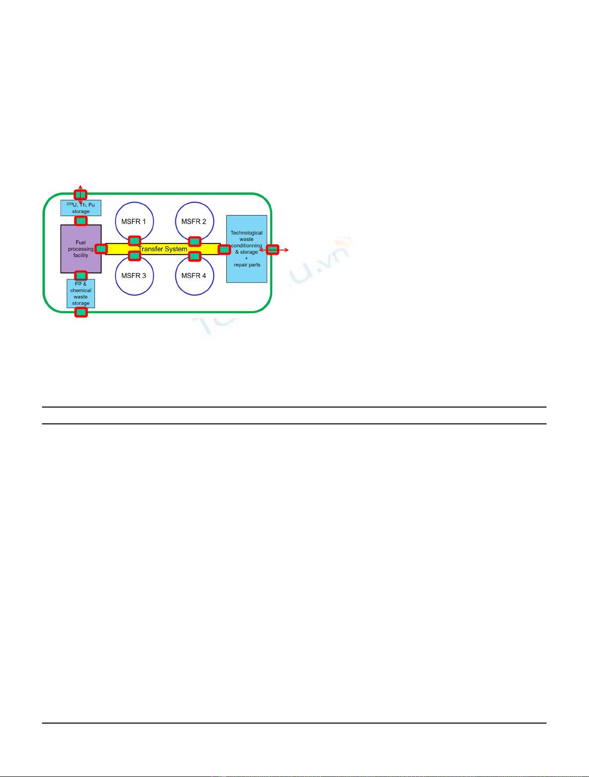
The setup considered for an MSFR nuclear plant site
delivering large power consists in several buildings that are
interconnected by devices able to ensure the transfer of
these radioactive materials.
Due to the penetrant 2.6 MeV gamma radiations (see
next section) from the Th/U fuel cycle, these transfers will
be achieved via remote control within enclosures fitted with
several confinement barriers and a gamma ray protection
shield. Safety also requires a physical separation (door)
between the system’s buildings to ensure confinement. All
the materials and equipment can thus be conveyed via
chambers equipped with control devices (radiation mea-
surement, visual and thermal monitoring, scales, etc.) as
illustrated in Figure 1.
This scheme is not final: the question of which elements
are shared between reactors and which are dedicated to a
single reactor is not decided from the safety point of view. It
is likely that a more complex structure will be necessary, in
2 M. Allibert et al.: EPJ Nuclear Sci. Technol. 6, 5 (2020)
particular for the fuel cleaning unit, depending on the
proliferation resistance analysis results. The schematic will
be modified as the design progresses.
3.2 Target identification
Here, the goal is to determine where in the installation a
fissile material diversion could occur. The amounts of
materials and the isotopic vector of the actinides present in
the various zones of the MSFR system can be estimated
through the simulations of the fuel salt evolution according
to the parameters characterizing the reactor, the fuel
cleaning methodology and the operation mode. The
numbers listed below correspond to the “reference reactor”
presented in the preceding section, if it is started with
233
U
or a mix of 13% enriched U and the TRUs from a PWR [7].
The inventories of the isotopes of U, Pu, and Np are
shown in Table 1, for an 18 m
3
fuel volume and 7.7 m
3
fertile
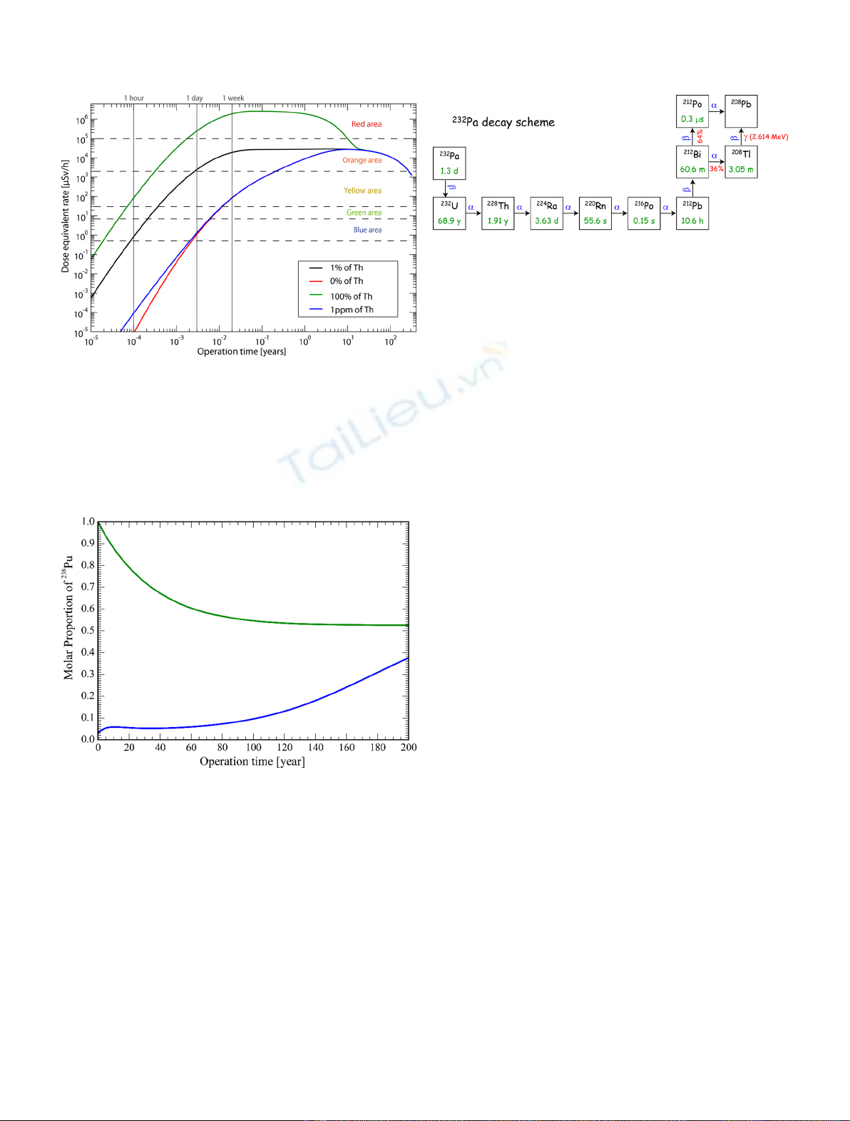
blanket volume. Special attention has been given to
232
U
whose presence is considered to favor proliferation
resistance due to the 2.6 MeV gamma radiation generated
in its decay to
208
Pb.
232
U, whose half-life is 68.9 yr is
mainly produced via the (n,2n) reaction of fast neutrons on
232
Th nuclei, followed by an (n,g) reaction on
231
Pa:
232
90Th !
ðn;2nÞ
231
90Th !
bð25:5hÞ
231
91Pa
231
91Pa !
ðn;gÞ
232
91Pa !
bð1:31dÞ
232
92U:
8
<
:
The 2.6 MeV gamma radiation systematically co-occurs
with
233
U in the reactors based on the Th/U cycle. It makes
the remote handling of Th mandatory (see Fig. 2) and it
facilitates the detection of any attempted diversion of this
element.
Table 1 shows that plutonium’s isotopic vector is
degraded compared to that in the solid fuel of today’s
reactors, so it is not an attractive target. This is also
illustrated in Figure 3: the
238
Pu content stays consistently
Table 1. Isotope inventories (in kilograms, unless otherwise stated).
Isotope Half life (Short)
233
Ustarted 1y
enr
U+TRU started 1y Fuel salt Equ. 200y Fertile salt
232
U 69.8 y 3.5 142 g 13 34 g
233
U 4976 514 4658 58.5
234
U 143.9 12.8 1769 0
235
U 4.9 2506 510 0
236
U 0 149.5 562 0
237
U0 0
238
U 0 16300 1 0
232
U/U 700 ppm 50 ppm 1700 ppm 600 ppm
233
U/U 97% 2.7% 62% 99%
238
Pu 0 239 161 0
239
Pu 0 3265 66 0
240
Pu 0 1617 57 0
241
Pu 0 641 48 0
242
Pu 0 491 10 0
239
Pu/Pu 52% 19%
231
Pa 300 g 900 g 10 630 g
232
Pa 1.3 d 3.9 g 0 15 g 15.4 g
233
Pa 27 d 124 45.6 108 13
234
Pa 6.8 h 20 g 6.5 g 15.7 g 1 g
236
Np 0 7 g 9.4 g 0
237
Np 0 377.8 145 0
238
Np 2.1 d 0 507 g 200 g 0
239
Np 2.4 d 0 5.4 0 0
Fig. 1. Schematic representation of a nuclear site with 4 reactors
sharing common facilities. Green rectangles with red contours
represent monitoring chambers for any transfer in or out the
elements. Internal transfers on site are made by remote handling
(yellow).
M. Allibert et al.: EPJ Nuclear Sci. Technol. 6, 5 (2020) 3
larger than 5%. Since the proliferation resistance of this
fissile material has already been studied in other reactor
concepts and is not specific to MSR, it is not treated here as
mentioned previously. Finally, pure
237
Np can be obtained
but its use as alternative nuclear explosive has been
questioned [10]. Two targets remain to be considered: U
from breeding in the blanket and stored for future use to
start other reactors, and the Pa.
In conclusion, the diversion of nuclear material
contained in the reactor core seems impossible, so that
we will consider only the possibilities for nuclear material
diversions within the chemical processing unit.
3.3 Pathway identification
The fuel contains
233
Pa with 140 ppm
232
Pa, giving a dose
rate for the uranium formed (containing, at the beginning
of decay, up to 3000 ppm
232
U) on the order of 200 to 6000
times larger than the dose rate associated with reactor
grade Pu. The 2.6 MeV gamma ray emitted by the
208
Pb
formed by the decay of
232
Pa is the main contributor to this
dose rate and its attenuation requires a large shielding
mass.
Concealed diversion of these targets is possible only
after they have been separated from the other actinides and
under the provision that such separation allows a
significant reduction of the 2.6 MeV gamma radiation
emissions. This separation could take place in the salt
cleaning unit, before lanthanide separation. This salt
cleaning unit seems the most sensitive from the prolifera-
tion resistance point of view. To grasp the stakes, the decay
chain leading from
232
Pa to
208
Pb has to be examined, as
well as the separation means that it would be used for
normal system operation but could be misused for the
purposes of diversion. The decay chain leading to
208
Pb is
shown in Figure 4.
The 2.6 MeV gamma radiation can be suppressed in two
ways. One is to isolate the Pa from all the other actinides,
then wait for the decay of the
232
Pa so as to divert
233
Pa
after having extracted from it the U and its descendants, in
one or several passages within the fuel salt cleaning unit
(see Fig. 5). The other is to efficiently separate the Th and
its descendants from the U to cut the decay chain at the
228
Th level. The second option suspends the 2.6 MeV
gamma radiation while the first attenuates it indefinitely.
The procedures used to clean the fuel or extract the U from
the blanket have to be evaluated in this perspective.
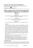
Figure 6 illustrates the reduction of the radiation
emitted by the stored Pa that is obtained with a periodical
extraction of the U. Such an extraction limits the radiation
level so that the storage of Pa in the cleaning unit may be
undetected. The recycling of
232
U in the fuel salt weakens
the effect of the concealed storage on the fuel’s gamma
radiation emission. If the Pa remains in the cleaning unit
for 3 weeks, the emission due to the Pa that has not been
transformed into U becomes very small, making its
diversion from the nuclear site much easier.
Fig. 2. Evolution of the dose equivalent rate of a fuel salt batch in
the storage area of the chemical cleaning unit for four scenarios of
thorium extraction, with a mention to the 5 areas defined by the
French classification [9]. The case “0% of thorium”(red curve) is
the weaker concerning proliferation resistance since the dose
equivalent rate is the lower during the first hours.
Fig. 3. Time evolution of the
238
Pu content in the total Pu for a
reactor started with
233
U (green curve) and with
enriched@13%
U+
TRU (blue curve).
Fig. 4.
232
Pa decay chain leading to
208
Pb and the emission of the
associated 2.6 MeV gamma ray. If the most attractive targets (Pa
and U) are separated from the elements to their right, the gamma
ray emission will be suspended for a relatively long time, allowing
their undetected diversion.
4 M. Allibert et al.: EPJ Nuclear Sci. Technol. 6, 5 (2020)
3.4 Countermeasures
The main target for Pa or U diversion is the fertile blanket
of a breeder reactor. Since an MSFR can be operated
without a blanket while ensuring quasi break-even fuel
breeding, a first option consists in delivering only blanket-
free MSFRs to risk prone states. The need then arises to
periodically inject fissile material in the fuel salt so as to
ensure good reactivity precludes any diversion of Pa: the
flow of necessary fissile material would have to be increased
to compensate for the missing U that the diverted Pa would
have produced. In the presence of a blanket, the most
efficient diversion is that of Pa that rests on the ability to
separate the elements in the fuel cleaning unit. The
methods used in this unit are not precisely determined and
options remain to be chosen. Similarly, work needs to be
done to determine how this unit will be organized.
3.4.1 Choice of actinide separation methods
The main proliferation risk is related to the possibility of
separating the Pa from the other actinides and from all the
232
Pa descendants (U, Th, and Ra essentially). This
separation would be done at first when the Pa is extracted
from the fuel salt and the blanket and subsequently
repeated regularly to conceal the storage of Pa. The two
operations can be distinct but must make use of the
methodology available in the fuel salt cleaning unit. The
less efficient the separation techniques are, the better the
proliferation resistance will be. Indeed, the fuel composi-
tion adjustment as well as the utilization of the U from
breeding do not require a good separation efficiency, since
the actinides have to be recycled. It is thus possible to limit
the risks associated with these means of separation by
opting for inefficient separation methods.
Two methods are being considered for the extraction of
the actinides: fluorination and reduction (chemical or
electrochemical) in a metallic bath.
Fluorination consists in forming gaseous actinide
fluorides via the oxidation of the salt by gaseous fluorine.
These fluorides are produced at temperatures ranging
between 600 and 900 °C, the gases being subsequently
cooled and condensed on inert or reactive (alkaline
fluorides) media. Depending on the operating conditions,
the U (UF
6
) and other actinides (Pa, Np, Pu) are also
removed but not the Th, or the minor actinides. The
fluorination has another function, i.e. the extraction of
some elements such as O, I, S, Se, Te, Cr, Mo which produce
fluorides with low condensation temperatures, lower than
or similar to that of UF
6
. This means that it is not easy to
condense the wastes and the actinides separately. Ideally,
all the actinide fluorides would be condensed together in a
temperature range that would allow the separation of a
large part of the wastes. The non-separation of the
actinides on distinct physical containers could be a means
to reinforce proliferation resistance. This issue needs
further study.
Using the fluorination device to periodically remove the
U produced by the decay of Pa, by vaporizing only the U,
would leave the Th and the Ra with the Pa without
suspending the decay chain leading to
208
Pb. If the U and
the Pa were to be vaporized together (requiring high
temperature), then another separation, that of Pa/U,
would have to be done immediately, while avoiding the
vaporization of PaF
5
(at low temperature).
The reduction of actinides to a metallic state dissolved in
liquid Bi is a method that, in principle, doesnot allow as good
a separation of the elements as fluorination (on the order of
90% in one passage, compared to >99% in the case of
fluorination) A difficulty, that has already been identified, is
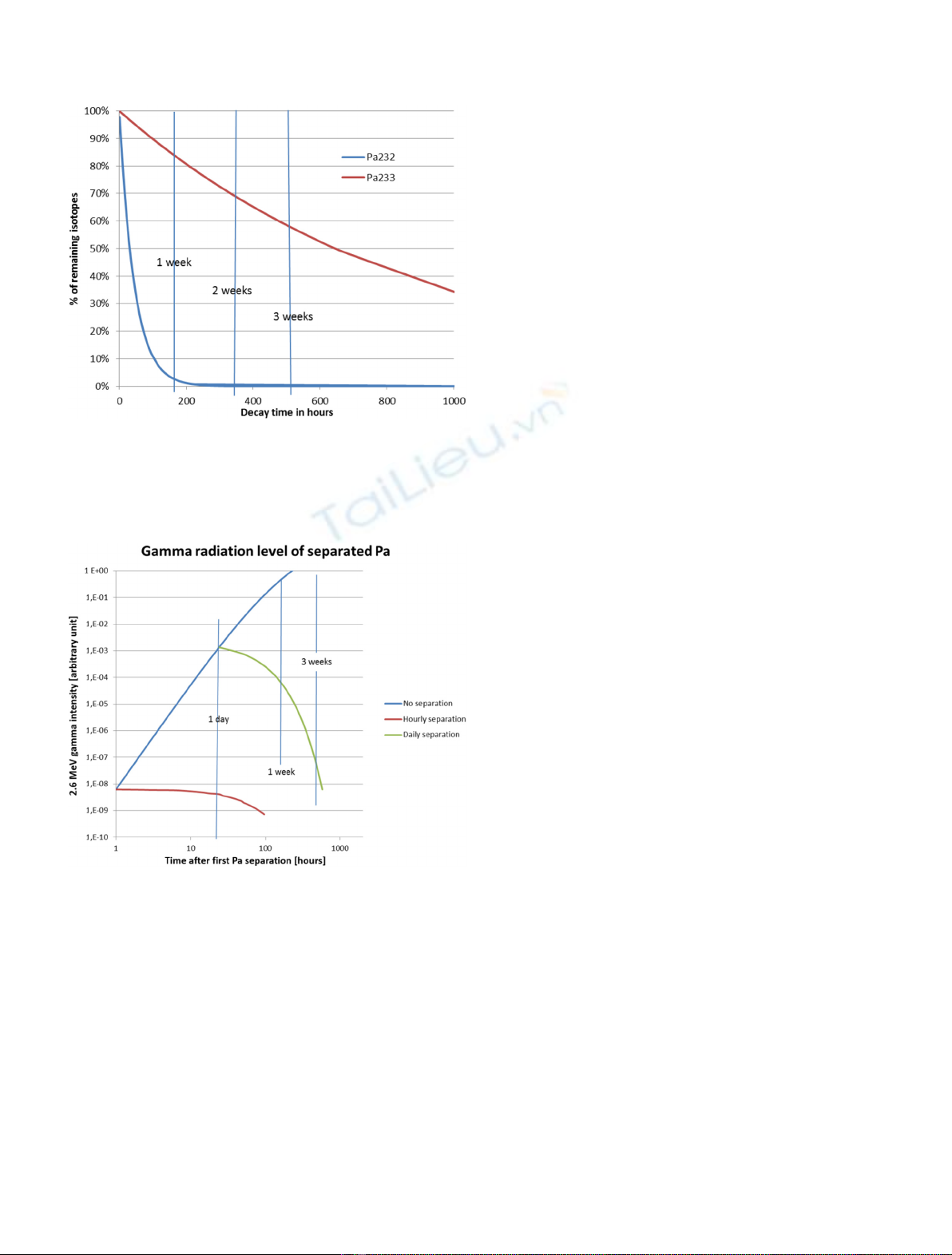
Fig. 5. Remaining Pa isotope fractions after Pa isolation. After
3 weeks of decay, the remaining fractions are 58%
233
Pa and
13 ppm
232
Pa (respectively 70% and 560 ppm after 2 weeks).
Fig. 6. Influence on the radiation level of a periodic extraction of
the U and its descendants. An hourly extraction seems to be the
most frequent feasible. A daily extraction is easier to implement
but the radiation level of the diverted materials is then five orders
of magnitude larger.
M. Allibert et al.: EPJ Nuclear Sci. Technol. 6, 5 (2020) 5


![Bài tập trắc nghiệm Kỹ thuật nhiệt [mới nhất]](https://cdn.tailieu.vn/images/document/thumbnail/2025/20250613/laphong0906/135x160/72191768292573.jpg)
![Bài tập Kỹ thuật nhiệt [Tổng hợp]](https://cdn.tailieu.vn/images/document/thumbnail/2025/20250613/laphong0906/135x160/64951768292574.jpg)

![Bài giảng Năng lượng mới và tái tạo cơ sở [Chuẩn SEO]](https://cdn.tailieu.vn/images/document/thumbnail/2024/20240108/elysale10/135x160/16861767857074.jpg)


