
Gasoline Direct Injection
INTRODUCTION
In recent years, legislative and market requirements have driven the need to reduce fuel
consumption while meeting increasingly stringent exhaust emissions. This trend has
dictated increasing complexity in automotive engines and new approaches to engine
design. A key research objective for the automotive engineering community has been the
potential combination of gasoline-engine specific power with diesel-like engine
efficiency in a cost-competitive, production-feasible power train. One promising engine
development route for achieving these goals is the potential application of lean burn
direct injection (DI) for gasoline engines. In carburetors the fuel is sucked due to the
pressure difference caused by the incoming air. This will affect the functioning of the
carburetor when density changes in air are appreciable. There was a brief period of
electronically controlled carburetor, but it was abandoned due to its complex nature. On
the other hand in fuel injection the fuel is injected into the air.
TRANSITION OF FUEL SUPPLY SYSTEM
The transition of the fuel supply system used in automobiles is graphically shown below.
In carburetor the fuel from the fuel chamber is sucked in by the pressure variation caused
due to the incoming air. The fuel then mixes with the air and reaches the cylinder through
the inlet manifold. Where as in a port injection system the fuel to the cylinder is supplied
by a separate fuel injector placed near the inlet valve of the cylinder. And in a direct
injection system the fuel to the cylinder is supplied by a fuel injector placed inside the
cylinder.
1
Fig1: Transition of Fuel Supply System

Gasoline Direct Injection
OPERATING DIFFICULTIES FOR A CARBURETOR.
Some problems associated with comfortable running of the carburetor are discussed here.
1. Ice formation: The vaporisation of the fuel injected in the current of the air
requires latent heat and the taken mainly from the incoming air. As a result of this,
the temperature of the air drops below the dew point of the water vapour in the air
and it condenses and many times freeze into ice if the temperature falls below dew
point temperature.
2. Vapour Lock: The improved volatility of modern fuels and the necessity of
providing heat to prevent the ice formation, has created carburetion difficulties
due to vaporisation of fuel in pipes and float chamber. The heating may also occur
due to petrol pipes being near the engine. If the fuel supply is large and supply is
small, a high velocity will result causing high vacuum. This causes considerable
drop which may also cause the formation of vapour bubbles. If these bubbles
formed accumulate at the tube bend, then they may interrupt the fuel flow from
the tank or the fuel pump and engine will stop because of lack of fuel. Vapour
lock is formed because of rapid bubbling of fuel and usually happens in hot
summer.
3. Back Firing: During the starting of an engine under cold working conditions, the
usual manipulation of the choke varies the mixture from too lean to too rich. A
very lean mixture will burn very slowly and the flame may still exist in cylinder
when the exhaust valve is about to open. The fresh charge in the intake manifold
is about to open. The fresh charge in the intake manifold is not so diluted as when
inducted into the cylinder and mixed with the clearance gases and consequently
burn more rapidly than the charge in the cylinder. If lean charge comes in contact
with flames existing in the cylinder, there will be flash of flame back through the
intake manifold, burning the charge therein and causing the customary back firing
in the carburetor.
ADVANTAGES OF FUEL INJECTION OVER CARBURETOR
The fuel injection eliminates several intake manifold distribution problems. One
of the most difficult problems in a carbureted system is to get the same amount
and richness of air-fuel mixture to each cylinder. The problem is that the intake
manifold acts as a storing device, sending a richer air fuel mixture to the end
2

Gasoline Direct Injection
cylinders. The air flows readily around the corners and through various shaped
passages. However the fuel, because it is heavier is unable to travel as easily
around the bends in the intake manifold. As a result, some of fuel particles
continue to move to the end of the intake manifold, accumulating there. This
enriches the mixture going the end cylinder. The center cylinder closest to the
carburetor gets the leanest mixture. The port injection solves this problem because
the same amount of fuel is injected at each intake valve port. Each cylinder gets
the same amount of air-fuel mixture of the same mixture richness.
Another advantage of the fuel injection system is that the intake manifold can be
designed for the most efficient flow of air only. It does not have to handle fuel.
Also, because only a throttle body is used, instead of a complete carburetor, the
hood height of the car can be lowered.
With fuel injection, fuel mixture requires no extra heating during warm up. No
manifold heat control valve or heated air system is required. Throttle response is
faster because the fuel is under pressure at the injection valves at all times. An
electric fuel pump supplies the pressure. The carburetor will depend on
differences in air pressure as the force that causes the fuel to feed into the air
passing through.
Fuel injection has no choke, but sprays atomized fuel directly into the engine. This
eliminates most of the cold start problems associated with carburetors.
Electronic fuel injection also integrates more easily with computerized engine
control systems because the injectors are more easily controlled than a mechanical
carburetor with electronic add-ons.
Multi port fuel injection (where each cylinder has its own injector) delivers a more
evenly distributed mixture of air and fuel to each of the engine's cylinders, which
improves power and performance.
Sequential fuel injection (where the firing of each individual injector is controlled
separately by the computer and timed to the engine's firing sequence) improves
power and reduces emissions.
3
Gasoline Direct Injection
ELECTRONIC FUEL INJECTION
The main components of electronic fuel injection are described below.
1. Engine Control Unit (ECU)
2. Sensors
3. Fuel Injectors
Engine Control Unit (ECU): This unit is the heart of electronic injection system which is
responsible for metering the quantity of fuel supplied to each cylinder. The unit
contains a number of printed circuits boards on which, a series of transistors,
diodes and other electronic components are mounted. This makes the vital data
analysing circuits responding to various input signals. After processing the input
data, the power output circuits in the control unit generates current pulses which
are transmitted to the solenoid injectors to operate the injector for the required
period.
For example, when the pedal of the vehicle is stepped on, the throttle valve (this is the
valve that regulates how much air enters the engine) opens up more, letting in more air.
The engine control unit (ECU) "sees" the throttle valve open with the help of sensors and
increases the fuel rate in anticipation of more air entering the engine. It is important to
increase the fuel rate as soon as the throttle valve opens; otherwise, when the gas pedal is
first pressed, there may be a hesitation as some air reaches the cylinders without enough
fuel in it. Sensors monitor the mass of air entering the engine, as well as the amount of
oxygen in the exhaust. The ECU uses this information to fine-tune the fuel delivery so
that the air-to-fuel ratio is just right.
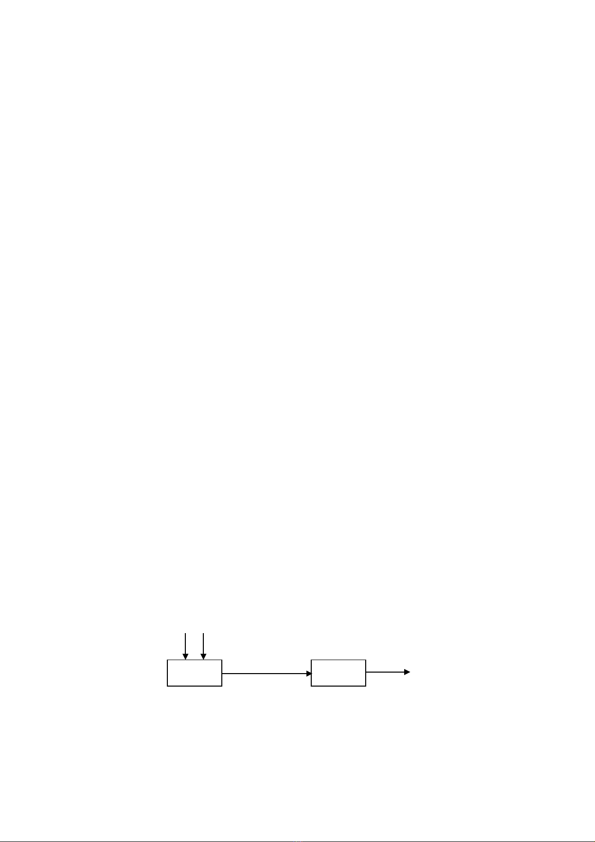
The ECU generally works in two operating modes, namely open loop and closed loop. In
closed loop Oxygen sensor is used to sense the quantity of excess Oxygen in the smoke
and this information is used for the next cycle of injection. This is also called feedback
mode. On the other hand in open loop system the Oxygen sensor is not used.
4
ECU Engine
Exhaust
Fig2: Open loop Operation
mode
Gasoline Direct Injection
Engine Sensors: In order to provide the correct amount of fuel for every operating
condition, the engine control unit (ECU) has to monitor a huge number of input
sensors. Here are just a few:
•Mass airflow sensor - Tells the ECU the mass of air entering the engine
•Oxygen sensor - The device measures the amount of oxygen in the exhaust gas
and sends this information to the electronic control unit. If there is too much
oxygen, the mixture is too lean. If there is too little, the mixture is too rich. In
either case, the electronic control unit adjusts the air fuel ratio by changing the
fuel injected. It is usually used with closed loop mode of the ECU.
5
ECU Engine Oxygen
Sensor
Exhaust
Fig3: Closed loop Operation mode
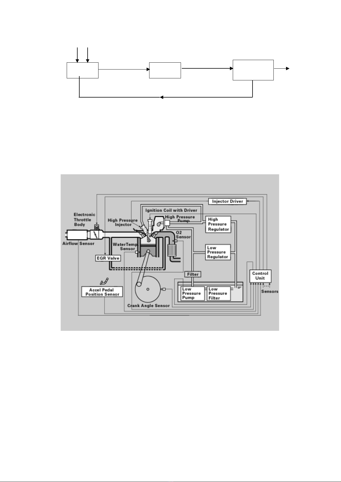
Fig4: Various Sensors used in a GDI system


![Thiết kế động cơ nén khí: Bài tập lớn [chuẩn nhất]](https://cdn.tailieu.vn/images/document/thumbnail/2025/20250808/kimphuong1001/135x160/92301754624152.jpg)
![Bài tập lớn nồi hơi - tua bin hơi tàu thủy [chuẩn nhất]](https://cdn.tailieu.vn/images/document/thumbnail/2025/20250804/kimphuong1001/135x160/51011754302684.jpg)

![Thiết kế hộp giảm tốc hai cấp: Đồ án môn học [chuẩn nhất]](https://cdn.tailieu.vn/images/document/thumbnail/2025/20250730/vijiraiya/135x160/99241753869588.jpg)


