3
Long-haul
.
Communication
None
of
the circuits that we have
so
far discussed are suitable as they stand for long haul
communication.
To
get
us
anywhere with long haul we need to address ourselves to the following
inescapably pertinent topics:
0
attenuation
(loss
of
signal strength over distance)
0
line loading (a way of reducing attenuation on medium length links)
0
amplification (how to boost signals on long haul links)
0
equalization (how to correct tonal distortion)
0
multiplexing (how to increase the number of ‘circuits’ that may be obtained from
one physical cable)
In
this chapter we discuss predominantly how these line issues affect analogue transmission
systems and how they may be countered. The effects on digital transmission are discussed in
later chapters.
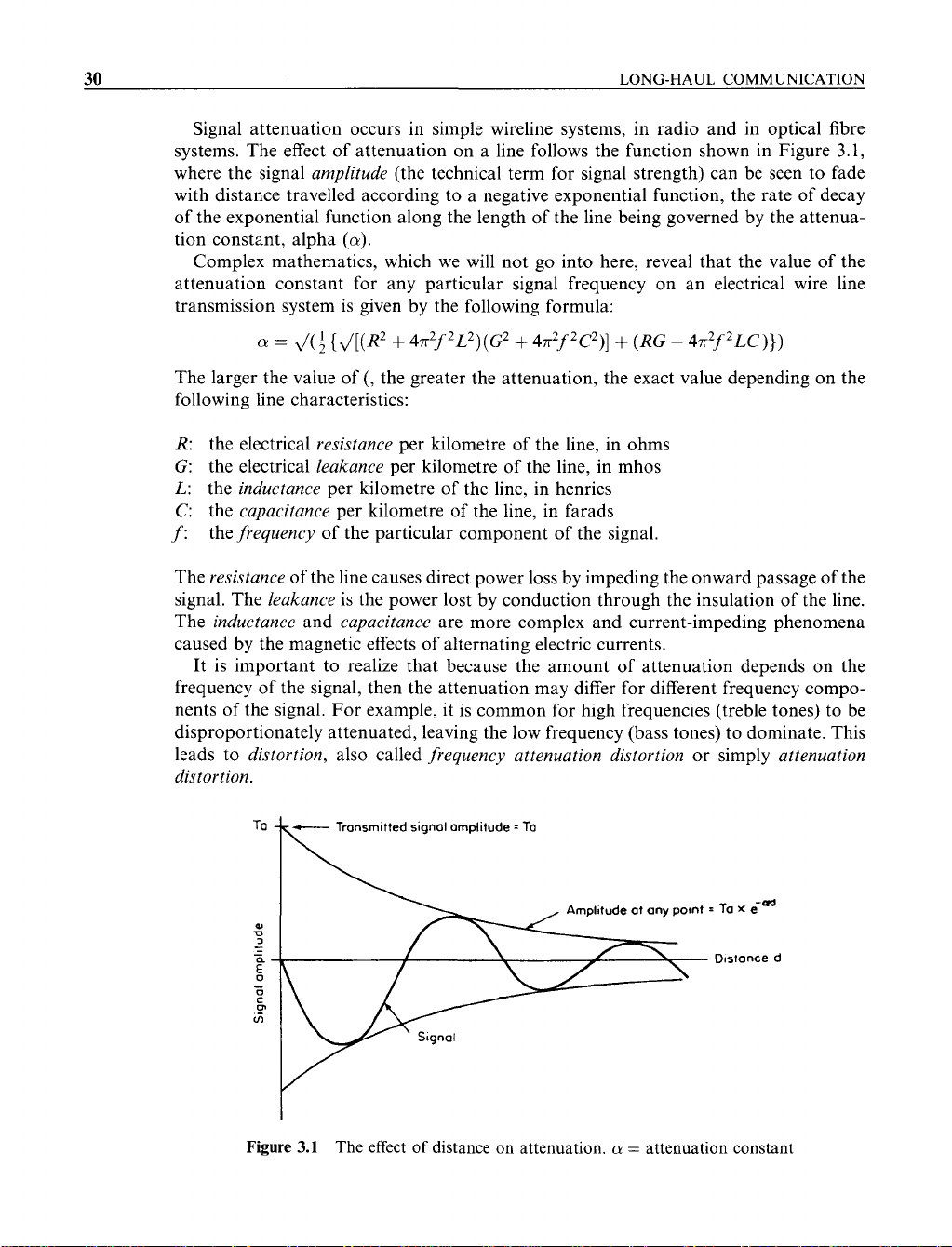
3.1 ATTENUATION AND REPEATERS
Sound waves diminish the further they travel and electrical signals become weaker as they
pass along electromagnetic transmission lines. With electrical signals the attenuation
(as this type
of
loss
in signal strength is called) is caused by the various electrical properties
of the line itself. These properties are known as the
resistance,
the
capacitance,
the
leakance
and the
inductance.
The attenuation becomes more severe as the line gets longer. On very
long haul links the received signals become
so
weak as to be imperceptible, and something
needs
to
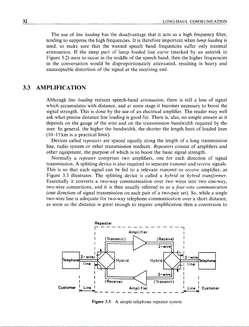
be done about it. Usually the attenuation in analogue transmission lines is
countered by devices called
repeaters,
which are located at intervals along the line, their
function being to restore the signal to its original wave shape and strength.
29
Networks and Telecommunications: Design and Operation, Second Edition.
Martin P. Clark
Copyright © 1991, 1997 John Wiley & Sons Ltd
ISBNs: 0-471-97346-7 (Hardback); 0-470-84158-3 (Electronic)
30
LONG-HAUL COMMUNICATION
Signal attenuation occurs in simple wireline systems, in radio and in optical fibre
systems. The effect of attenuation on a line follows the function shown in Figure
3.1,
where the signal
amplitude
(the technical term for signal strength) can be seen to fade
with distance travelled according to a negative exponential function, the rate of decay
of the exponential function along the length of the line being governed by the attenua-
tion constant, alpha
(a).
Complex mathematics, which we will not go into here, reveal that the value of the
attenuation constant for any particular signal frequency on an electrical wire line
transmission system is given by the following formula:
cli
=
J(i{J[(R2
+
47r2f2L2)(G2
+
47r2f2C2)]
+
(RG
-
47r2f2LC)})
The larger the value of
(,
the greater the attenuation, the exact value depending on the
following line characteristics:
R:
the electrical
resistance
per kilometre of the line, in ohms
G:
the electrical
leakance
per kilometre of the line, in mhos
L:
the
inductance
per kilometre of the line, in henries
C:
the
capacitance
per kilometre of the line, in farads
f:
the
frequency
of the particular component of the signal.
The
resistance
of the line causes direct power loss by impeding the onward passage of the
signal. The
leakance
is the power lost by conduction through the insulation of the line.
The
inductance
and
Capacitance
are more complex and current-impeding phenomena
caused by the magnetic effects of alternating electric currents.
It is important to realize that because the amount of attenuation depends on the
frequency of the signal, then the attenuation may differ for different frequency compo-
nents of the signal. For example, it is common for high frequencies (treble tones) to be
disproportionately attenuated, leaving the low frequency (bass tones) to dominate. This
leads to
distortion,
also called
frequency attenuation distortion
or simply
attenuation
distortion.
Amplltude at any pomt
=
Ta
X
e-&
U
3
Dosronce d
1\
c-
Transmitted signol omplitude
=
Ta
Figure
3.1
The effect
of
distance on attenuation.
cr
=
attenuation constant
LINE
LOADING
31
3.2
LINE
LOADING
As
the
inductance
and
capacitance
work against one another, a simple means of
minimizing the effect of unwanted attenuation and distortion is to increase the
inductance of the line to counteract some or all of the line capacitance.
Taking a closer look at the equation given in the last section, we find that attenuation
is zero when both resistance and leakance are zero, but will have a real value when
either resistance or leakance is non-zero. The lesson is that both the resistance and the
leakance of the line should be designed to be as low as is practically and economically
possible. This is done by using large
gauge
(or diameter) wire and good quality
insulating sheath.
A
second conclusion from the formula for the attenuation constant is that its value is
minimized when the inductance has a value given by the expression
L
=
CR/G henrieslkm
This, in effect, reduces the electrical properties of the line to a simple resistance, mini-
mizing both the attenuation and the distortion simultaneously. In practice, the
attenua-
tion
and
distortion
of
a line can be reduced artificially by increasing its inductance
L
ideally in a continuous manner along the line’s length. The technique is called
line
loading.
It can be achieved by winding iron tape or some other magnetic material
directly around the conductor, but it is cheaper and easier to provide a
lumped loading
coil
at intervals (say
1-2
km) along the line. The attenuation characteristics of unloaded
and loaded lines are shown in Figure
3.2.
Unloaded
line
/
a
-
..
Lump
loaded
line Continuously
loaded
line
-
Speech band
I
I
I
Signal frequency
Figure
3.2
Attenuation
characteristics
of
loaded
line
32
LONG-HAUL COMMUNICATION
The use of
line loading
has the disadvantage that it acts as a high frequency filter,
tending to suppress the high frequencies. It is therefore important when
lump loading
is
used, to make sure that the wanted speech band frequencies suffer only minimal
attenuation. If the steep part of lump loaded line curve (marked by an asterisk in
Figure
3.2)
were to occur in the middle of the speech band, then the higher frequencies
in the conversation would be disproportionately attenuated, resulting in heavy and
unacceptable distortion of the signal at the receiving end.
3.3
AMPLIFICATION
Although
line loading
reduces speech-band
attenuation,
there
is
still a loss of signal
which accumulates with distance, and at some stage it becomes necessary to boost the
signal strength. This is done by the use of an electrical amplifier. The reader may well
ask what precise distance line loading is good for. There is, alas, no simple answer as
it
depends on the gauge of the wire and on the transmission bandwidth required by the
user. In general, the higher the bandwidth, the shorter the length limit of loaded lines
(10-15
km is a practical limit).
Devices called
repeaters
are spaced equally along the length of a long transmission
line, radio system
or
other transmission medium.
Repeaters
consist of amplifiers and
other equipment, the purpose of which is to boost the basic signal strength.
Normally a
repeater
comprises two amplifiers, one for each direction of signal
transmission. A splitting device is also required to separate
transmit
and
receive
signals.
This is
so
that each signal can be fed to a relevant
transmit
or
receive
amplifier, as
Figure
3.3
illustrates. The splitting device is called a
hybrid
or
hybrid transformer.
Essentially it converts a two-way communication over two wires into two one-way,
two-wire connections, and it is then usually referred to as a
four-wire communication
(one direction of signal transmission on each pair of a two-pair set).
So,
while a single
two-wire line is adequate for two-way telephone communication over a short distance,
as soon as the distance is great enough to require amplification then a conversion to
Repeater
r--
--____---
---
l
I
Amplifier
I
Figure
3.3
A
simple telephone repeater system
AMPLIFICATION
33
four-wire communication is called for. Figure 3.3 shows
a
line between two telephones
with a simple telephone repeater in the line. Each repeater consists of two hybrid
transformers and two amplifiers (one for each signal direction).
The
amplijication
introduced at each repeater has to be carefully controlled to
overcome the effects of attenuation, without adversely affecting what is called the
stability
of the circuit, and without interfering with other circuits in the same cable.
Repeaters too far apart or with
too
little amplification would allow the signal current to
fade to such an extent as to be subsumed in the electrical
noise
present on the line.
Conversely, repeaters that are too close together or have too much amplification, can
lead to circuit instability, and to yet another problem known as
crosstalk.
A circuit is said to be unstable when the signal that it is carrying is over-amplified,
causing feedback and even more amplification. This in turn leads to even greater
feedback, and so on and on, until the signal is
so
strong that it reaches the maximum
power that the circuit can carry. The signal is now distorted beyond cure and all the
listener hears is a very loud singing noise. For the causes of this distressing situation let
us look at the simple circuit
of
Figure 3.4.
The diagram of Figure 3.4 shows a poorly engineered circuit which is electrically
unstable. At first sight, the diagram is identical to Figure 3.3. The only difference is that
various signal attenuation values (indicated as negative) and amplification values
(indicated as positive) have been marked using the standard unit
of
measurement, the
decibel (dB). The problem is that the net gain around the loop is greater than the net
loss. Let us look more closely. The hybrid transformer H1 receives the incoming signal
from telephone
Q
and transmits it to telephone
P,
separating this signal from the one
that will be transmitted on the outgoing pair of wires towards
Q.
Both signals suffer a
3 dB attenuation during this ‘line-splitting’ process. Adding the attenuation of
1
dB
which is suffered on the local access line by the outgoing signal coming from telephone
P,
the total attenuation of the signal by the time it reaches the output of hybrid H1 is
therefore 4 dB. The signal is further attenuated by
5
dB as a result of line
loss.
Thus the
input to amplifier A1 is
9
dB below the strength of the original signal. Amplifier A1 is
set to more than make up for this attenuation by boosting the signal by 13 dB,
so
that at
+
13
dB
Line
loss
Arnplifler
+l3
dB
Figure
3.4
An
unstable circuit