
* Corresponding author.
E-mail addresses: shr492@mail.usask.ca (S. Ramadurga Narasimharaju)
© 2019 Growing Science Ltd. All rights reserved.
doi: 10.5267/j.esm.2019.5.002
Engineering Solid Mechanics 7 (2019) 217-228
Contents lists available at GrowingScience
Engineering Solid Mechanics
homepage: www.GrowingScience.com/esm
Microstructure and fracture behavior of friction stir lap welding of dissimilar AA 6060-T5/ Pure
copper
Shubhavardhan Ramadurga Narasimharajua* and Surendran Sankunnyb
aDepartment of Mechanical Engineering, University of Saskatchewan, Saskatoon, Canada
bIndian Institute of Technology, Madras Chennai, India
A R T I C L EI N F O A B S T R A C T
Article history:
Received 27 December, 2018
Accepted 18 May 2019
Available online
18 May 2019
This study aims to understand the uncertainty about the optimum or best pin position (Dp) for
friction stir lap welding (FSLW) of Al-Cu. Tensile shear testing is used to determine the
Mechanical strength of FSL welds under static loading. Fracture strength (σLap) corresponding to
the maximum load in a test over the sample width is used as the strength value. Interface
microstructures differ depending on whether the tool pin penetrates the lapping interface. It has
been found that σLap values of the defect free weld samples vary quite significantly and in general
are significantly higher than those reported in the literature. When the pin penetration is close to
zero no intermetallic layers were formed, hence the value of σLap was zero. When the pin
penetration is 0.4mm, the commonly observed a thin Al–Cu interface layer forms and this layer
does not grow beyond 3µm. It is shown that the thin interfacial layer can withstand a high tensile-
shear load and thus the adjacent Al material shears to fracture. When the pin penetrates more than
0.4mm, the commonly observed mix stir zone (MSZ) forms and values of σLap are lower than that
of 0.4mm pin penetration welds but remain quite high.
© 2019 Growing Science Ltd. All rights reserved.
Keywords:
Friction stir lap welding
Aluminum
Copper
Interface microstructure
Intermetallic layer
Fracture strength
1. Introduction
Friction stir welding (FSW) is a solid state welding process invented and patented by The Welding
Institute (TWI), for butt and lap welding of ferrous and non-ferrous materials and plastics (Thomas et al.,
1993). As a good ability of this technique, sound quality weldments for similar Al-Al and dissimilar Al-
non Al alloys can be obtained using FSW joining method (Wang et al., 2018; Zhang et al., 2018;
Kumbhar & Bhanumurthy, 2012; Lomolino et al., 2005; Torabi et al., 2018; Pao et al., 2001; Zettler et
al., 2006; Sun et al., 2013; Aliha et al., 2018; Akbari et al., 2016). In general, it is well known that fusion
welding of one metallic alloy to another with considerably higher melting temperatures (referred to as a
large ∆T Melting couple, in this case it is Al to Cu) is important in many industries but are very
challenging due to physical mismatches such as differences in melting temperature, thermal expansion
and thermal conductivity can make the joining almost impractical using conventional welding
techniques. Formation of thick intermetallic layers (due to high heat input and liquation of aluminum) is
known to deteriorate mechanical properties of the joints (Mishra & Ma, 2005; Mishra & Mahoney, 2007;
Nandan et al., 2008; Threadgill et al., 2009; Murr, 2010; Lohwasser & Chen, 2009; Rai et al., 2011).
Therefore, development of FSW as a solid-state joining process is of high importance from both scientific

218
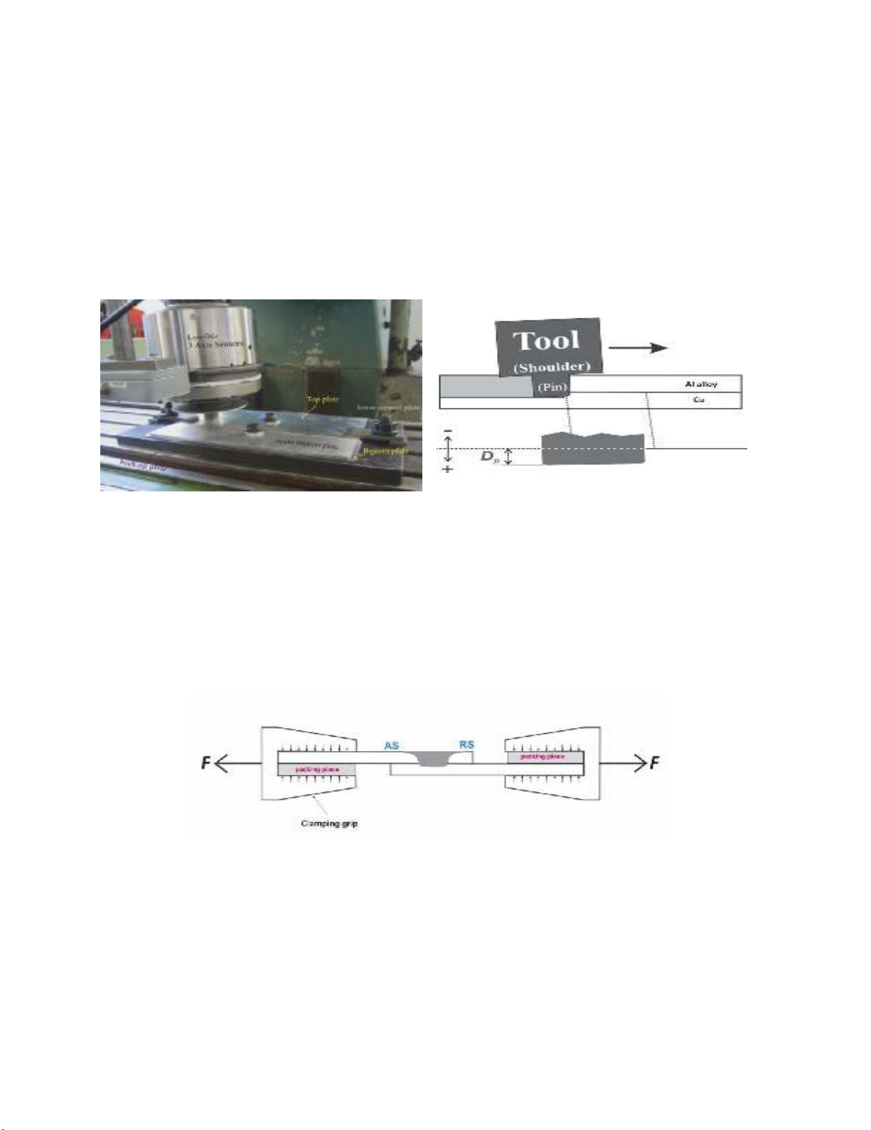
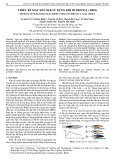
and industrial point of view. Fig. 1 illustrates FSLW during which a section of lapping surfaces of the
top and bottom plates is stirred and mixed in the stir zone (SZ) thus forming a weld behind the tool. In
FS welding of a large ∆T Melting couple, aided by frictional and deformation heat, metallurgical bond is
established through diffusion and subsequent formation of interfacial intermetallic. A metallurgical bond
is a condition for a quality joint and a metallurgical bond implies low electric resistance, although
intermetallic are commonly viewed to affect joint strength adversely. The cited studies on FS Al-to-Cu
(including : Galvao et al., 2011, 2012a,b; Elrefaey et al., 2004, 2005; Abdollah-Zadeh et al,. 2008; Saeid
et al., 2010; Xue et al., 2010, 2011a,b; Satya Narayana Gupta et al., 2012; Firouzdor & Kou, 2012;
Akbari & Behnagh, 2012; DebRoy & Bhadeshia, 2010; Ouyang et al., 2006; Aliha et al., 2018, 2019;
Esmaeili et al., 2011 a,b; Liu et al., 2011; Genevois et al., 2011; Sharma et al., 2018) basically converges
on three the general aspects;1: Al-Cu couple being FS weld able, 2: it is difficult to achieve sound FSW
dissimilar Al-Cu joints due to the formation of brittle interfacial intermetallic layer compound (IMCs) at
the interface and 3: it is hard to control the formation of IMCs. Early investigation by Elrefaey et al.
(2004, 2005) on Al-Cu FSLW clearly established that the tool pin (0.1 and 0.2 mm) penetrating to Cu
are the conditions for a metallurgical joint to be established at the Al-Cu interface, resulting in a good
joint strength. Although detailed quantification was not done in their study, it was clear from their
micrographs that the interface region of welds made with pin penetration is a highly irregular structure
of mix layers. Ouyang et al. (2006) attributed the poor weldability to various brittle IMCs formed in the
Nugget zone (NZ). It is well documented that several parameters, such as tool offsetting, rotation rate,
and traverse speed, influenced the weld properties of the dissimilar Al-Cu FSW joints by Carlone et al.
(2015). Abdollah-Zadeh et al. (2008) and Saeid et al. (2010) reported irregular shape and inhomogeneous
distribution of IMCs at the interface during FSLW of Al-Cu with minimum pin penetration. Xue et al.
(2010, 2011a,b) study was an attempt to correlate the σLap to the lower rotation rate and larger bonding
area, under the condition of pin penetration. Their data shows that increasing the pin diameter results in
a larger Al-Cu bonding area exhibited a higher failure load of 268N/mm with the specimen failing in the
HAZ on the aluminium side. However, the meaning of the referred larger bonding area results in wide
area intermetallics is unclear and difficult to understand. Furthermore Xue et al. (2011a) reported that
Al4Cu9, and Al2Cu and formed at the interface region, based on x-ray diffraction analysis. However,
assigning the structure of Al4Cu9, and Al2Cu to a mixed region relying on x-ray diffraction analysis is
not reliable due to very low intensity. Sharma et al (2018), attributed the effect of different FSW tool pin
profiles on the microstructure and the hardness. Firouzdor and Kou (2012) reported weld strength equal
to 183 N/mm for conventional Al-Cu FSL weld when the pin penetration at least 0.1mm to Cu. This is a
very low weld strength value and from their micrographs a continuous metallurgical bond in Al-Cu
interface cannot be confirmed, However, good metallurgical bonding and reasonable tensile properties
were ensured when modified lap was used, with increase in weld strength close to 342 N/mm. Satya
Narayana Gupta et al. (2012) suggested that better joint properties are obtained in the joints fabricated
using straight fluted tool compared with tapered tool and their Micrographs of stir zone are not clear, and
Al-Cu interface joint features are not provided. In this paper FSLW of Al-Cu, to explain how interface
microstructures affect the fracturing process during tensile-shear testing and thus joint strength. A
possible control method for producing Al-Cu welds for a higher joint strength can then be suggested.
Fig. 1. Schematics illustrations of FSLW of Al-Cu
2. Experimental procedure
All FSLW experiments were conducted using FV200 milling machine and thus the mode of FS was
displacement control. Schematic illustration of FSLW process has already been provided in Fig. 1. Fig.
S. R. Narasimharaju and S. Sankunny / Engineering Solid Mechanics 7 (2019)
219
2 shows an actual FSLW experiment. A LowstirTM device, which is also shown in Fig. 2, was used in
each FSLW experiment to monitor the downforce. Al 6060-T5 (300x100x6mm) alloy placed on top of
the and pure Cu (300x100x2mm) work pieces were FSL welded. A sufficiently thick top plate is used to
avoid fracture at the HAZ during tensile shear testing, and to instead cause fracture along the Al-Cu
interface. A major series of experiments were conducted with 1400 rpm, (and 710 rpm is only used to
demonstrate the difference in temperature at SZ, Fig 5) as a rotational speed (ω), 60mm/min as a traverse
speed (v),3 degrees of tilt angle(Ө) and tool pin penetration Dp= 0 mm and Dp=0.4 mm respectively
from the top surface of the bottom plate (Fig.3). Tools were made using H13 tool steel and the left-hand
threads of the pins were made with a 1 mm pitch and a 0.6 mm actual depth. The diameter of the concave
shoulder was 18 mm and the pin outside diameter was 6 mm. K-type thermocouple was used to measure
the FSLW interface temperature.
Fig. 2. FSLW using a FV200 milling machine with
a LowstirTM force measuring device
Fig. 3. Schematic illustration of tool positioning
during FSLW showing pin penetration depth
Tensile-shear testing of FS lap welds has been the major method used for evaluating strength of FSL
welds in literature. Test samples, 16 mm wide, perpendicular to the welding direction were machined
from the welded plates. Fig. 4 illustrates the positioning of a sample together with supporting pieces.
Samples were tested at a constant crosshead displacement rate of 3 mm/min using a 50 KN Tinus Olsen
tensile testing machine, with a 50-mm extensometer attached. The strength of a lap sample cannot be
expressed using the normal load/area, as the stress distribution along the joint area during tensile-shear
test is highly uneven. Instead, maximum failure load in a test divided by the width of the sample, σLap,
is taken as strength
Fig. 4. Schematic illustration of tensile-shear testing
3. Results and discussion
3.1. Temprature measurement
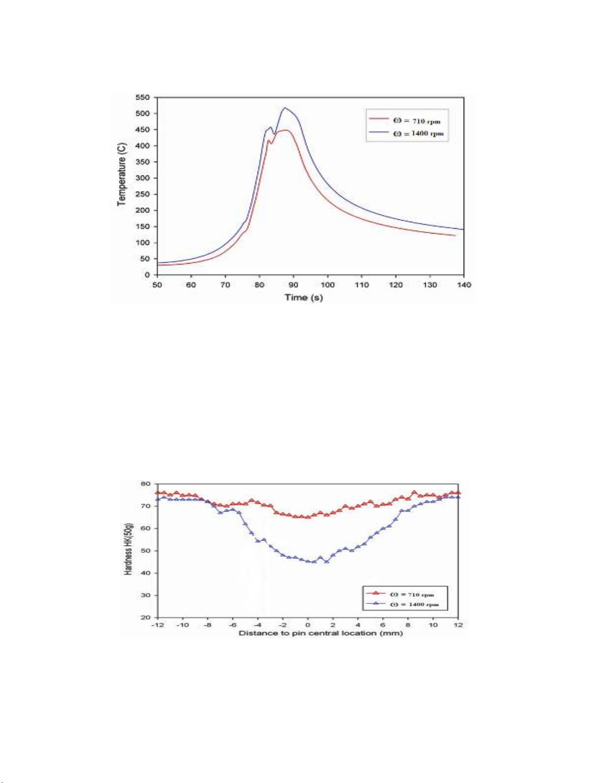
To justify FSW is solid state welding process, (no melting of base metals). K-type thermocouple was
placed at Al-Cu interface to monitor the temperature. Traces of temperature at stir zone (SZ) of these
welds, during FSLW, are also presented in Fig 5. In each trace, there are disturbances in the peak
220
temperature region because the thermocouple was pushed slightly by the lower stir flow as the pin
approached the thermocouple. The weld made using ω=1400 rpm has obtained higher peak temperature
(Tsz =520oC) and spent longer time at the elevated temperatures, compared to the weld made using
ω=710 rpm (with Tsz =445oC).
Fig. 5. Measured temperature at SZ of welds made using ω=1400 rpm and and ω=710 rpm with
v=60mm/min
3.2 Microhardness distribution in stir zone
As the larger grains have less grain boundaries hence they would impose less restriction to the
dislocation movement, resulting in lower hardness and local strength. Therefore, the SZ exhibited the
lowest hardness, compare to the other region, as it had the largest grains hardness of SZ for the weld
made using ω=1400 rpm is considerably lower than that of the weld made using ω=710 rpm (Fig. 6).
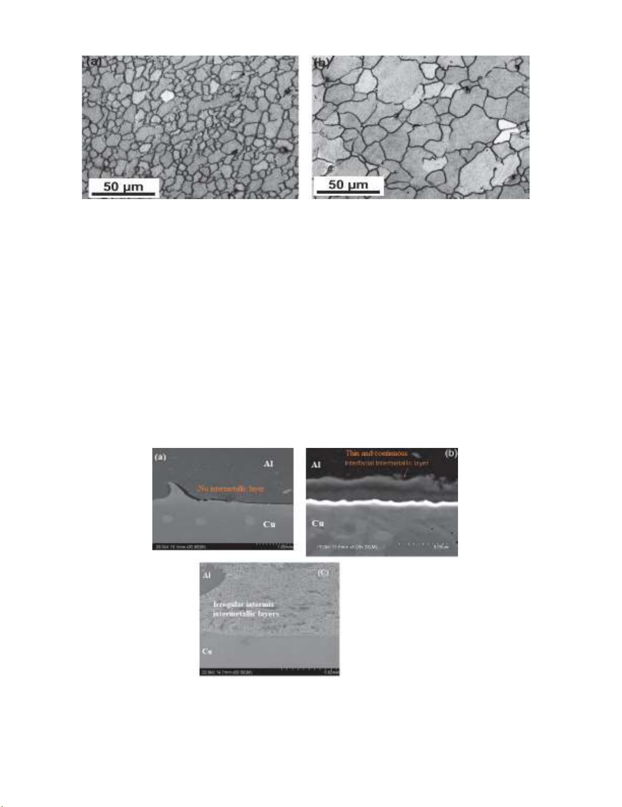
This is due to difference in grain size produced at SZ of these welds, as shown in Fig 7. The grains in the
weld made using ω=1400 rpm is considerably larger than the grains in the weld made using ω=710 rpm.
Traces of temperature at SZ of these welds, during FSLW, are also presented in Fig5. Consequently, the
recrystallized grains at SZ of the weld made using ω=1400 rpm could grow more, resulting in larger
grains with subsequent reduced hardness.
Fig. 6. Knoop hardness distribution (transverse to welding direction measured for the two welds made
using ω =1400 rpm, 710 rpm and v=60mm/min
S. R. Narasimharaju and S. Sankunny
/ Engineering Solid Mechanics 7 (2019)
221
Fig. 7. Microstructure of SZ for the welds made using ν =60 mm/min: (a) ω =710 rpm and (b) ω =1400 rpm
3.3 Microstructure analysis
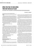
Three selected samples are shown here to illustrate the importance of interface microstructures and
based on this illustration a suggestion of FSLW control for maximum strength can then be made. Fig.
8(a) is the first example where no intermetallic compound layer (IMC) were formed for Dp≈0, It should
be noted that there is no research work available in literature for this condition especially for Al-Cu
FSLW. The reason for not forming any intermetallic layer at the Al-Cu weld interface may be because
copper has conducted heat faster, since copper has higher thermal conductivity, but for the similar FSLW
conditions (pin penetration, Dp≈0) for Al-Steel FSLW, a continuous and thin intermetallic layer has been
reported (Shubhavardhan & Surendran 2018). This is just to compare the effect of FSLW pin penetration
(Dp) on different large ∆T Melting couple, however, FSLW of Al-steel and Al-copper is totally different,
cannot compare the results), with maximum value of σLap. When Dp≈0.4 as shown in in fig. 8(b), a thin
and continuous interface intermetallic layer (up to 3μm in thickness) is observed. When the pin
penetration is further increased a non-uniform, irregular intermix MSZ can be observed which is shown
in fig 8(c). The area of MSZ largely corresponds to the area of the pin penetrated copper and this zone is
a mixture of Al-Cu intermetallic thin pieces embedded in the recrystallized Cu grains.
Fig. 8. Cross sectional view of an Al-Cu FSL weld made with ω = 1,400 rpm, v = 60 mm/min, (a) Dp≈0
with no intermetallic layer formed at the interface, (b) Dp≈0.4 mm thin and continuous intermetallic layer
formed, and (c) Dp>0.4 mm displaying irregular intermix intermetallic layer (MSZ)


![Thép cán kết cấu hàn: [Thông tin chi tiết/Báo giá/Hướng dẫn lựa chọn]](https://cdn.tailieu.vn/images/document/thumbnail/2020/20201014/maryland93/135x160/2381602661478.jpg)


![Giáo trình Cấu trúc dữ liệu và giải thuật - Trường CĐ Cơ điện Hà Nội [Mới nhất]](https://cdn.tailieu.vn/images/document/thumbnail/2026/20260323/lionelmessi01/135x160/58171774381670.jpg)


![Giáo trình Tiện nâng cao (Nghề Cắt gọt kim loại, Trình độ Cao đẳng) - Trường Cao đẳng Cơ điện Hà Nội [Mới nhất]](https://cdn.tailieu.vn/images/document/thumbnail/2026/20260323/lionelmessi01/135x160/48101774403543.jpg)


