Chapter 18
426
(++5(++9
When transferring data, the two states on the bus are Differential 0 and Differ-
ential 1. A Differential 0 exists when D+ is a logic low and D- is a logic high. A
Differential 1 exists when D+ is a logic high and D- is a logic low. Chapter 19
has details about the voltages.
The Differential 0/1s don’t translate directly into zero and one data states but
instead indicate either a change in logic level, no change in logic level, or a bit
stuff, as explained later in this chapter.
# 25
The Single-ended 0 (SE0) state occurs when both D+ and D- are logic low. The
bus uses the SE0 state when entering the EOP, Disconnect, and Reset states.
# 29
The complement of SE0 is the Single-ended 1 (SE1). This state occurs when
both D+ and D- are logic high. This is an invalid bus state and should never
occur except as specified in the USB battery-charging specification.
((0
In addition to the Differential 0 and Differential 1 states, which are defined by
voltages on the lines, USB also defines two Data bus states, J and K. These are
defined by whether the bus state is Differential 0 or Differential 1 and the speed
of the cable segment:
Defining the J and K states in this way makes it possible to use one terminology
to describe an event or logic state even though the voltages on low- and
full-speed lines differ. For example, a Start-of-Packet state exists when the bus
changes from Idle to the K state. On a full-speed segment, the state occurs
when D- becomes more positive than D+, while on a low-speed segment, the
state occurs when D+ becomes more positive than D-.
%
) 3
Differential 0 Data J Data K
Differential 1 Data K Data J

Packets on the Bus
427
In the Idle state, no drivers are active. On a full-speed segment, D+ is more pos-
itive than D-, while on a low-speed segment, D- is more positive than D+.
Shortly after device attachment, a hub determines whether a device is low or
full speed by checking the voltages on the Idle bus at the device’s port.
$"
When a device is in the Suspend state, a Data K state at the device’s port signi-
fies a resume from Suspend.
#2+2%
The Start-of-Packet (SOP) bus state exists when the lines change from the Idle
state to the K data state. Every transmitted low- or full-speed packet begins with
an SOP.
2+2%
The End-of-Packet (EOP) state exists when a receiver has been in the SE0 state
for at least one bit time followed by a Data J state for at least one bit time. A
receiver may optionally accept a shorter minimum time for the Data J state. At
the driver, an SE0 is approximately two bit widths. Every transmitted low- or
full-speed packet ends with an EOP.
(
A downstream port is in the Disconnect state when an SE0 has persisted for at
least 2.5 µs.
A downstream port enters the Connect state when the bus has been in the Idle
state for at least 2.5 µs and no more than 2.0 ms.
$
When an SE0 has lasted for 10 ms, the device must be in the Reset state. A
device may enter the Reset state after an SE0 of at least 2.5 µs. A full-speed
device that is capable of high-speed communications performs the high-speed
handshake during the Reset state.
Chapter 18
428
On exiting the Reset state, a device must be operating at its correct speed and
must respond to communications directed to the default address (00h).
)5GG G
Many of the high-speed bus states correspond to states for low and full speed,
but a few are unique to high speed, and some low/full-speed states have no
equivalents at high speed.
. 2(++5(++9
The two bus states that exist when transferring high-speed data are High-speed
Differential 0 and High-speed Differential 1. As with low and full speeds, a
High-speed Differential 0 exists when D+ is a logic low and D- is a logic high,
and a High-speed Differential 1 exists when D+ is a logic high and D- is a logic
low. The voltage requirements differ at high speed, however, and high speed has
additional requirements for AC differential levels.
. 2((0
The definitions for High-speed Data J and Data K states are identical to those
for full-speed J and K.
0
The Chirp J and Chirp K bus states are present only during the high-speed
detection handshake. The handshake occurs when a USB 2.0 hub has placed a
downstream bus segment in the Reset state. In a Chirp J, D+ is more positive
than D-, and in a Chirp K, D- is more positive than D+.
A high-speed device must use full speed on attaching to the bus. The
high-speed detection handshake enables a high-speed device to tell a USB 2.0
hub that the device supports high speed and to transition to high-speed com-
munications.
As Chapter 4 explained, shortly after detecting device attachment, a device’s
hub places a device’s port and bus segment in the Reset state. When a
high-speed-capable device detects the Reset, the device places its line in the
% !
Differential 0 High-speed Data K
Differential 1 High-speed Data J

Packets on the Bus
429
Chirp K state for 1–7 ms. A hub that communicates upstream at high speed
detects the Chirp K and in response, sends an alternating sequence of Chirp K
and Chirp J. The sequence continues until shortly before the Reset state ends.
On detecting the Chirp K and Chirp J sequence, the device disconnects its
full-speed pull-up, enables its high-speed terminations, and enters the Default
state. A hub that communicates upstream at low/full speed ignores the device’s
Chirp K. The device doesn’t see the answering sequence and knows that com-
munications must take place at full speed.
. 2#-"
The High-speed Squelch state indicates an invalid signal. High-speed receivers
must include circuits that detect the Squelch state, indicated by a differential
bus voltage of 100 mV or less.
. 2
In the High-speed Idle state, no high-speed drivers are active and the
low/full-speed drivers assert SE0. Both D+ and D- are between -10 and +10
mV.
#+. 2%
A Start-of-High-speed Packet (HSSOP) exists when a segment changes from
the High-speed Idle state to the High-speed Data K state. Every high-speed
packet begins with a Start of High-speed Packet.
+. 2%
An End of High-speed Packet (HSEOP) exists when the bus changes from the
High-speed Data K or Data J state to the High-speed Idle state. Every
high-speed packet ends with an End of High-speed Packet.
. 2(
Removing a high-speed device from the bus also removes the high-speed line
terminations at the device. Removing the terminations causes the differential
voltage at the hub’s port to double. A differential voltage of at least 625 mV on
the data lines indicates the High-speed Disconnect state. A USB 2.0 hub con-
tains circuits that detect this voltage.
Chapter 18
430
PP5
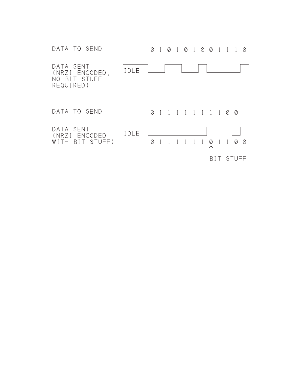
All data on a USB 2.0 bus is encoded using a format called non-return to zero
inverted (NRZI) with bit stuffing. The encoding ensures that the receiver
remains synchronized with the transmitter without the overhead of sending a
separate clock signal or Start and Stop bits with each byte.
If you use an oscilloscope or logic analyzer to view USB data on the bus, you’ll
find that reading the bits isn’t as easy as matching voltage levels to logic levels.
Instead of defining logic zeroes and ones as voltages, NRZI encoding defines
logic zero as a voltage change, and logic one as a voltage that remains the same.
Figure 18-1 shows an example. Each logic zero results in a change from the pre-
vious state. Each logic one results in no change in the voltages. The bits trans-
mit least-significant-bit first.
Fortunately, USB hardware performs the encoding and decoding automatically
so device developers and programmers don’t have to do it. The encoded data is
harder to interpret on an oscilloscope or logic analyzer, but as Chapter 17
showed, a protocol analyzer will decode the data for you.
Figure 18-1. In NRZI encoding, a 0 causes a change and a 1 causes no change.
Bit stuffing adds a 0 after six consecutive 1s.


![Ngân hàng đề thi trắc nghiệm Kiến trúc máy tính [mới nhất]](https://cdn.tailieu.vn/images/document/thumbnail/2026/20260514/hoahongxanh0906/135x160/49281779160279.jpg)


%20--%3e%3cdefs%3e%3cstyle%3e%20.st0%20{%20fill:%20%23fff;%20}%20.st1%20{%20fill:%20%237800fa;%20}%20%3c/style%3e%3c/defs%3e%3cpath%20class='st1'%20d='M117.78,12.18H43.11c2.9,3.47,4.65,7.94,4.65,12.82,0,5.6-2.3,10.66-6.01,14.29h76.02l7.22-13.56-7.22-13.56Z'/%3e%3cg%3e%3cpath%20class='st0'%20d='M53.58,26.17h-.59v-1.46h.59v-4.96h2.83c1.78,0,2.67.94,2.67,2.82v5.76c0,1.87-.89,2.81-2.67,2.81h-2.83v-4.96ZM55.36,21.37v3.34h1.1v1.46h-1.1v3.34h1.01c.61,0,.91-.37.91-1.1v-5.93c0-.74-.3-1.1-.91-1.1h-1.01Z'/%3e%3cpath%20class='st0'%20d='M65.99,31.14h-1.8l-.31-2.07h-2.19l-.31,2.07h-1.64l1.82-11.39h2.62l1.82,11.39ZM65.28,18.04c-.25.46-.51.77-.75.94-.21.15-.47.22-.79.22-.26,0-.57-.07-.92-.22l-.38-.15c-.14-.05-.26-.07-.37-.07-.3,0-.53.18-.71.54l-.91-.68c.25-.46.51-.77.75-.94.21-.14.48-.21.79-.21.26,0,.57.07.92.21l.38.15c.14.05.26.07.37.07.3,0,.53-.18.71-.54l.91.68ZM61.91,27.52h1.73l-.87-5.76-.87,5.76Z'/%3e%3cpath%20class='st0'%20d='M74.53,26.89v1.52c0,1.91-.89,2.86-2.67,2.86s-2.67-.95-2.67-2.86v-5.93c0-1.91.89-2.86,2.67-2.86s2.67.95,2.67,2.86v1.11h-1.69v-1.22c0-.75-.31-1.12-.93-1.12s-.93.37-.93,1.12v6.15c0,.74.31,1.11.93,1.11s.93-.37.93-1.11v-1.63h1.69Z'/%3e%3cpath%20class='st0'%20d='M81.4,31.14h-1.8l-.31-2.07h-2.19l-.31,2.07h-1.64l1.82-11.39h2.62l1.82,11.39ZM75.9,19.2l1.52-1.91h1.71l1.51,1.91h-1.61l-.76-.95-.75.95h-1.61ZM77.32,27.52h1.73l-.87-5.76-.87,5.76ZM83.1,15.99l-1.76,1.91h-1.26l1.17-1.91h1.86Z'/%3e%3cpath%20class='st0'%20d='M84.86,19.75c1.78,0,2.67.94,2.67,2.82v1.48c0,1.87-.89,2.81-2.67,2.81h-.85v4.28h-1.79v-11.39h2.64ZM84.01,21.37v3.86h.85c.58,0,.87-.36.87-1.08v-1.71c0-.71-.29-1.07-.87-1.07h-.85Z'/%3e%3cpath%20class='st0'%20d='M93.51,19.75c1.78,0,2.67.94,2.67,2.82v1.48c0,1.87-.89,2.81-2.67,2.81h-.85v4.28h-1.79v-11.39h2.64ZM92.66,21.37v3.86h.85c.58,0,.87-.36.87-1.08v-1.71c0-.71-.29-1.07-.87-1.07h-.85Z'/%3e%3cpath%20class='st0'%20d='M98.8,31.14h-1.79v-11.39h1.79v4.88h2.03v-4.88h1.83v11.39h-1.83v-4.88h-2.03v4.88Z'/%3e%3cpath%20class='st0'%20d='M105.36,24.55h2.46v1.62h-2.46v3.34h3.09v1.63h-4.88v-11.39h4.88v1.63h-3.09v3.18ZM108.17,17.29l-1.76,1.91h-1.26l1.17-1.91h1.86Z'/%3e%3cpath%20class='st0'%20d='M112.2,19.75c1.78,0,2.67.94,2.67,2.82v1.48c0,1.87-.89,2.81-2.67,2.81h-.85v4.28h-1.79v-11.39h2.64ZM111.35,21.37v3.86h.85c.58,0,.87-.36.87-1.08v-1.71c0-.71-.29-1.07-.87-1.07h-.85Z'/%3e%3c/g%3e%3ccircle%20class='st1'%20cx='25'%20cy='25'%20r='20'/%3e%3cpath%20class='st0'%20d='M32.78,19.27c2.92,0,4.43,2.55,5.28,5.33l.71,2.17c.14.38-.33.75-.71.75h-5.61c.19-.33.24-.71.09-1.08l-.75-2.45c-.43-1.32-.99-2.64-1.79-3.77.75-.57,1.65-.94,2.78-.94h0ZM25,18.38c3.25,0,4.9,2.78,5.89,5.89l.76,2.45c.14.42-.33.8-.8.8h-11.69c-.42,0-.94-.38-.8-.8l.75-2.45c.99-3.11,2.64-5.89,5.89-5.89h0ZM25,11.35c1.74,0,3.11,1.37,3.11,3.11s-1.37,3.11-3.11,3.11-3.11-1.41-3.11-3.11,1.41-3.11,3.11-3.11h0ZM17.27,19.27c1.08,0,1.98.38,2.73.94-.8,1.13-1.37,2.45-1.74,3.77l-.8,2.45c-.14.38-.05.75.09,1.08h-5.56c-.42,0-.9-.38-.75-.75l.71-2.17c.9-2.78,2.41-5.33,5.33-5.33h0ZM17.27,12.91c1.51,0,2.78,1.27,2.78,2.83s-1.27,2.83-2.78,2.83-2.83-1.27-2.83-2.83,1.27-2.83,2.83-2.83h0ZM32.78,12.91c1.56,0,2.78,1.27,2.78,2.83s-1.23,2.83-2.78,2.83-2.83-1.27-2.83-2.83,1.27-2.83,2.83-2.83h0ZM27.07,28.56v.09c0,.57-.24,1.08-.61,1.46h0v.05c-.38.33-.9.57-1.46.57s-1.08-.24-1.46-.61h0c-.38-.38-.61-.9-.61-1.46v-.09h1.41v.09c0,.19.05.38.19.47v.05c.09.09.28.19.47.19s.38-.09.47-.19v-.05c.14-.09.24-.28.24-.47t-.05-.09h1.41ZM30.99,28.56v.09c0,1.65-.66,3.16-1.74,4.24-1.08,1.08-2.59,1.79-4.24,1.79s-3.16-.71-4.24-1.79l-.05-.05c-1.04-1.08-1.7-2.55-1.7-4.2v-.09h1.41v.09c0,1.27.47,2.4,1.27,3.25h.05c.85.85,1.98,1.37,3.25,1.37s2.4-.52,3.25-1.37c.85-.8,1.37-1.98,1.37-3.25v-.09h1.37ZM34.99,28.56v.09c0,2.78-1.13,5.28-2.92,7.07-1.79,1.79-4.29,2.92-7.07,2.92s-5.23-1.13-7.07-2.92c-1.79-1.79-2.92-4.29-2.92-7.07v-.09h1.41v.09c0,2.4.94,4.53,2.5,6.08,1.56,1.56,3.72,2.5,6.08,2.5s4.52-.94,6.08-2.5c1.56-1.56,2.5-3.68,2.5-6.08v-.09h1.41Z'/%3e%3c/svg%3e)