http://www.iaeme.com/IJMET/index.asp 567 editor@iaeme.com
International Journal of Mechanical Engineering and Technology (IJMET)
Volume 10, Issue 03, March 2019, pp. 567-575. Article ID: IJMET_10_03_058
Available online at http://www.iaeme.com/ijmet/issues.asp?JType=IJMET&VType=10&IType=3
ISSN Print: 0976-6340 and ISSN Online: 0976-6359
© IAEME Publication Scopus Indexed
VORTEX DYNAMIC INVESTIGATION OF WING
SLOTTED GAP OF SAAB JAS GRIPEN C-LIKE
FIGHTER
Sutrisno
Department of Mechanical and Industrial Engineering, Faculty of Engineering, Universitas
Gadjah Mada, Yogyakarta, Indonesia 55281
Setyawan Bekti Wibowo
Department of Mechanical and Industrial Engineering, Faculty of Engineering, Universitas
Gadjah Mada, Yogyakarta, Indonesia 55281
Sigit Iswahyudi
Department of Mechanical and Industrial Engineering, Faculty of Engineering, Universitas
Gadjah Mada, Yogyakarta, Indonesia 55281
Department of Mechanical Engineering, Faculty of Engineering, Universitas Tidar, Magelang,
Indonesia 56116
Tri Agung Rohmat
Department of Mechanical and Industrial Engineering, Faculty of Engineering, Universitas
Gadjah Mada, Yogyakarta, Indonesia 55281,
ABSTRACT
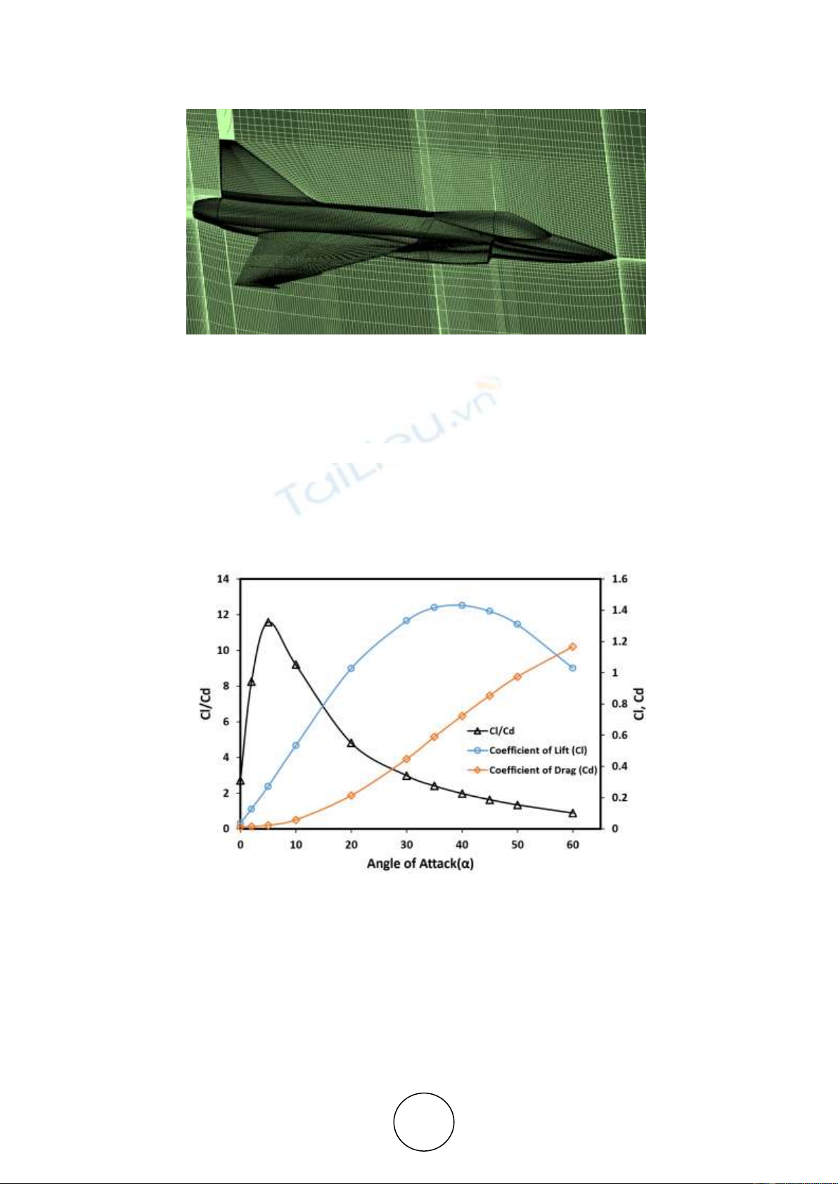
Canard fighters generally configured with wing canard-deltas and would generate
an airflow phenomenon producing vortex cores and lifts. The lift distribution would
stall at a high angle of attack (AoA). This study investigated the vortex dynamic of
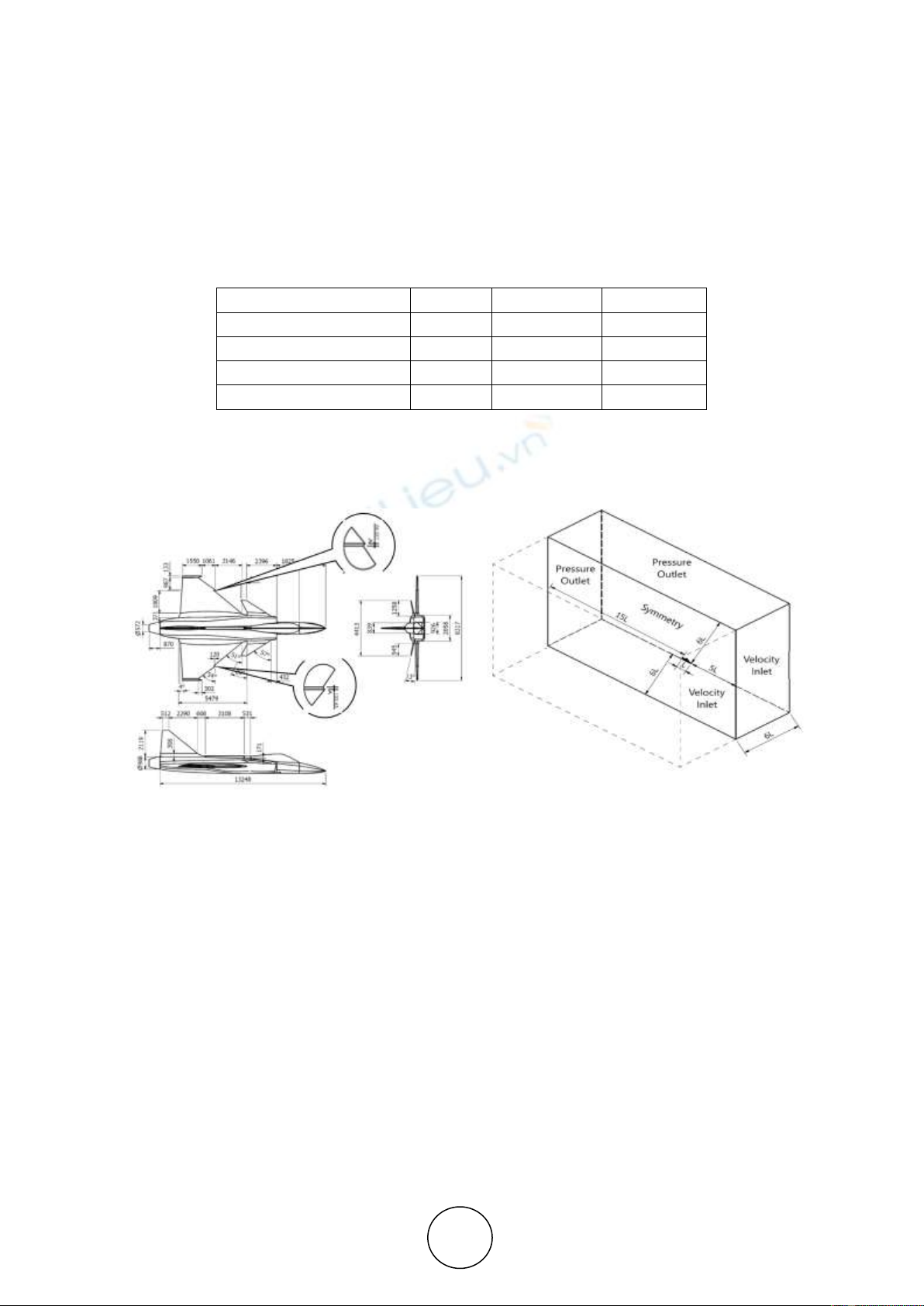
wing canard delta configurations of the Saab JAS Gripen C-like model which create
different wing planform than other fighters. The slotted leading edge of the Gripen
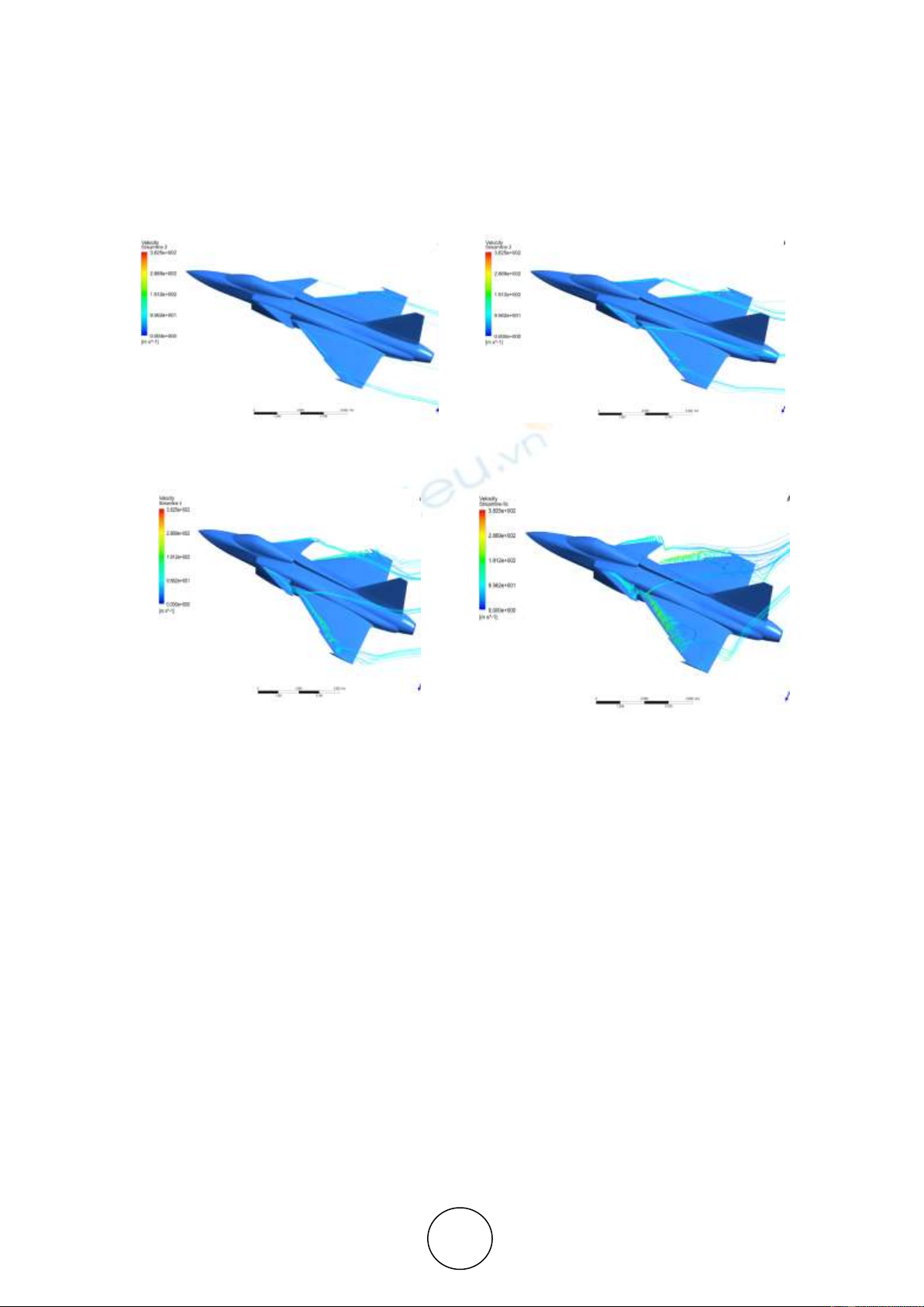
would develop a strong vortex core on the outer wing, on the same direction with the
spin of wing vortex; the outer core would drag the inner vortex core and strengthened.
Consequently, the vortex core streamlined in a leading edge of the wing would begin
to detach, resulting rolled-up vortices in the wing leading edge followed by a solid
laminar stream which tends to curl out. The trailing edge of the wing tended to
laminarize backward. The result would be a negative surface pressure on the leading
edge above the canard and on the wing which causes more negative surface pressures.
An increase in AoA will generate a closer vortex breakdown location to the wing
leading edge. The location was calculated as the ratio of the axial velocity value to
Vortex Dynamic Investigation of Wing Slotted Gap of Saab Jas Gripen C-Like Fighter
http://www.iaeme.com/IJMET/index.asp 568 editor@iaeme.com
free velocity (U/U∞) at a value of 0.1. As the AoA increased, the vortex breakdown
location moved forwards, upwards, and moved away from the fuselage.
Keywords : slotted leading edge, outer vortex core, high AoA, laminarize backward.
Cite this Article Sutrisno, Setyawan Bekti Wibowo, Sigit Iswahyudi and Tri Agung
Rohmat, Vortex Dynamic Investigation of Wing Slotted Gap of Saab Jas Gripen C-
Like Fighter, International Journal of Mechanical Engineering and Technology, 10(3),
2019, pp. 567-575.
http://www.iaeme.com/IJMET/issues.asp?JType=IJMET&VType=10&IType=3
1. INTRODUCTION
The delta wing study with computational processes generally uses the κ-ω turbulent model.
The reason is that using a turbulent Shear Stress Transport (SST) κ-ω model will predict high
accuracy flow separation, as the most appropriate choice for delta wing flow [1][3]. This
CFD simulation was strengthened by mesh independence test [4].
Zhang et al. have numerically investigated the canard-forward swept aircraft focusing on
interference between canard and wings [5]. Simulation of numerical fighter F-16XL models
for geometry and computational grids with structured and unstructured grids have also been
carried out using delayed detached-eddy simulations, as well as on flight conditions using
fluid dynamics computational near-body CFD / off body hybrid [6][8].
Several prominent scientists have investigated several fighters. Boelens has modeled CFD
flow around the X-31 fighter at high AoA [9]. Chen et al. have explored the sideslip effect of
high AoA vortex flow in close pair canard configuration [10]. Ghoreyshi et al. have validated
the simulation of Canard TransCruiser's static and forced flow of motion [11]. Ghoreyshi et
al. have modeled the transonic aerodynamic load of pitching X-31 aircraft [12]. Schütte and
Rein have examined numerically and experimentally unstable simulations around X-31 [13].
The purpose of this paper is to analyze the vortex dynamics of the SAAB JAS Gripen C-
like aircraft model in terms of performance, visualization of flowline above the canard and
wing, streamlined visualization above the canard and wing, streamline above the limiting wall
shear streamline on aircraft surface, wall-pressure distribution as well as pressure and surface
breakdown location. By knowing the characteristics of the dynamic vortex of the SAAB JAS
Gripen C-like aircraft model one can identify its excellence and find suggestions for
improvements that might be sought and improved further towards improving performance and
achievement.
2. RESEARCH METHODS
The model observed in this research was the SAAB JAS Gripen C-Like fighter model, as
shown in Figure 1, with several simplifications in symmetrical models, and several detailed
images, such as antennas. In this research, nets on fighter planes were made by identifying
parts of the plane and then dividing them into several blocks based on changes in the plane's
surface. Hexahedral nets were arranged by changing the size of the net, starting from the part
of the wall as the smallest size and enlarging logarithmic to the outside [8].
The optimal number of cells was obtained by conducting a mesh independence test, as
shown in Table 1. The previous test with 5 million cells, had reached a convergence of lift
strength coefficient values. In the case of this model, the number of cells made was 6,012,908
(~ 6 million). To determine the smallest mesh size on the wall, the y+ value was 4, with the
lowest cell value 0.017 mm.
Dogfighting of the fighter was conducted at slow speeds, i.e. at 0.3 M. When a Mach
number was at a higher value, it caused drag divergence. This was caused by the shock waves
Sutrisno, Setyawan Bekti Wibowo, Sigit Iswahyudi and Tri Agung Rohmat
http://www.iaeme.com/IJMET/index.asp 569 editor@iaeme.com
formation at the upper surface of the airfoil, causing flow separation and an adverse pressure
gradient on the back of the wing. Thus the vortex dynamics pattern around the fighter would
be symmetrical, and the calculation was done by a half model to save time. Figure 2 displays
the net and the grid shape above the canard. The computational domain was square with half a
symmetrical model. The boundary conditions in the computational domain were determined,
including the inlet or speed inlet, outlet or pressure outlet, and the symmetrical plane.
Table 1 Mesh independent test for different cell number [14]
Criteria
AoA
Cl
Error
Boelens, 2012
300
1.02157
1.3 million grids
300
1.074078
5.14%
3.1 million grids
300
1.042085
2.01%
5.2 million grids
300
1.026022
0.44%
This study involved several variations of the AoA ranging from 200 to 700. The flow rate
was set at an inlet velocity of 0.3 M (114. m/s) flowing on the surface of the plane with a
0.08% turbulence intensity. The flow analysis employed the finite volume method based on
the Navier-Stokes equation.
(a)
(b)
Figure 1 Geometrical model (a) SAAB JAS Gripen C-like (b) computational domain structure
(modified [14]).
Vortex Dynamic Investigation of Wing Slotted Gap of Saab Jas Gripen C-Like Fighter
http://www.iaeme.com/IJMET/index.asp 570 editor@iaeme.com
Figure 2 Structured grid SAAB JAS Gripen C like.
Vortex dynamics analysis was used to analyze the fuselage and RuV effects of the Gripen-
like fighter canard [15]. Vortex dynamics analysis involved flow visualization to analyze
fighters and a review of the measurement results. The flow visualization plot of the primary
vortex center was also presented, which may also generate the second vortex center.
Afterward, the measurement results were analyzed.
3. RESULT AND DISCUSSION
3.1. Performance
Figure 3 Distribution curve of CFD simulation of CL, CD and CL/CD of SAAB JAS Gripen C-like
aircraft
The simulation results in the form of CL, CD, and lifts to drag ratio was shown in Figure 3.
In Figure 3, the CL of a) SAAB JAS Gripen C-like aircraft became higher and b) the
distribution curve of CD simulation of SAAB JAS Gripen C-like aircraft were exposed.
Sutrisno, Setyawan Bekti Wibowo, Sigit Iswahyudi and Tri Agung Rohmat
http://www.iaeme.com/IJMET/index.asp 571 editor@iaeme.com
3.2. Streamline simulation on canard and wing at AoA 100, 200, 300 and 600
In Figure 4 displayed flow pathline speed of 102,9 m/s at AoA variation 300 and 600. In the
beginning, swirling flow pathlines described two vortex cores. Figure 4.a described a flow
pathline as well as a picture of the vortex core above the canard on AoA 100, along with a
picture of the vortex core above the wing.
(b)
(d)
Figure 4 Streamline visualization/ flow pathline above the canard and the wing at AoA a) 100, b) 200,
c) 300 and d) 600.
It appeared that the vortex core above the canard started dragging the vortex core above
the wing. Figure 4.b and c illustrated the vortex cores, above the canard from the canard and
above the wing began to coalesce became one core, gave strong drag on the vortex core in the
leading edge of the wing so that it started to release. In Figure 4.b and c, the rolled-up vortex
from the vortex core in leading edge wing started to release and to weaken, so that the laminar
flow behind it tended to weaken. The appearance in Figure 4.b and c showed the effect of the
slotted leading edge gave rise to a strong vortex core that dragged strong vortex core with the
direction getting stronger but tend to escape after the leading edge.
3.3. Limiting streamline on the aircraft surface above the wing at AoA 300 and
600.
In Figure 5.a and b one could see the wall-shear-streamlines above the wing at AoA 300 and
600. In Figure 5.a one could see the limiting streamline above canard flows laminar, as a result
of the flow path line in Figure 5.a flow over the canard tend to curl out, as well as above the
wing at the end of the leading edge tends to rolled up and behind it tends to laminate curved
out, with the trailing edge tends to be laminar straight backward. Whereas the streamlined