ISSN: 2615-9740
JOURNAL OF TECHNICAL EDUCATION SCIENCE
Ho Chi Minh City University of Technology and Education
Website: https://jte.edu.vn
Email: jte@hcmute.edu.vn
JTE, Volume 20, Issue 01, 02/2025
12
XNOR-Popcount, an Alternative Solution to the Accumulation Multiplication
Method for Approximate Computations, to Improve Latency and Power
Efficiency
Van-Khoa Pham1* , Lai Le2, Thanh-Kieu Tran Thi1
1Ho Chi Minh City University of Technology and Education, Vietnam
2Renesas Design Vietnam
*Corresponding author. Email: khoapv@hcmute.edu.vn
ARTICLE INFO
ABSTRACT
10/03/2024
Convolutional operations on neural networks are computationally intensive
tasks that require significant processing time due to their reliance on
calculations from multiplication circuits. In binarized neural networks,
XNOR-popcount is a hardware solution designed to replace the conventional
multiplied accumulator (MAC) method, which uses complex multipliers.
XNOR-popcount helps optimize design area, reduce power consumption, and
increase processing speed. This study implements and evaluates the
performance of the XNOR-popcount design at the transistor-level on the
Cadence circuit design software using 90nm CMOS technology. Based on
the simulation results, for the same computational function, if MAC operation
uses XNOR-popcount, the power consumption, processing time, and design
complexity can be maximally reduced by up to 69%, 50%, and 48%
respectively when compared to the method using conventional multipliers.
Thus, the XNOR-popcount design is a useful method to apply to edge-
computing platforms with minimalist hardware design, small memory space,
and limited power supply.
15/04/2024
15/04/2024
28/02/2025
KEYWORDS
Multiplyaccumulate operation;
XNOR-popcount;
Adder;
Latency;
Power consumption.
Doi: https://doi.org/10.54644/jte.2025.1537
Copyright © JTE. This is an open access article distributed under the terms and conditions of the Creative Commons Attribution-NonCommercial 4.0
International License which permits unrestricted use, distribution, and reproduction in any medium for non-commercial purpose, provided the original work is
properly cited.
1. Introduction
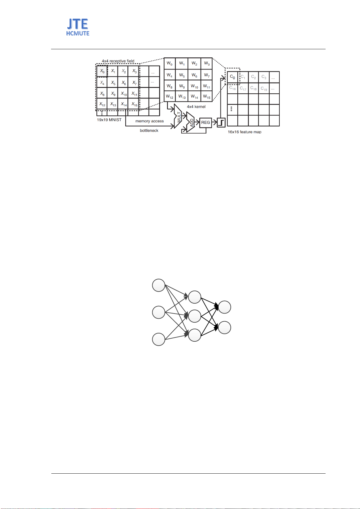
In convolutional neural networks, the convolution operation with MultiplyAccumulate (MAC)
requires complex computational hardware and high power consumption [1], [2]. The image pixels of
the receptive field are multiplied with the kernel (training weights). This multiplication is repeated until
the last pixel in the image, shifted by one pixel at a time [3]. As illustrated in Figure 1, assumed that the
convolution operation processes an input image of size 19×19 with the receptive field and the kernel
size of 4×4. To obtain a 16×16 feature map, 4096 times of multiplication, addition, and memory access
are needed. If floating-point numbers represent each value in the image pixels of the receptive field, the
convolution processing consumes a large amount of time and power due to the computation of
multiplication on floating-point data and frequent data movement between memory and processor [4],
[5]. Thus, if the data movement between memory and processor can be limited and the multiplication
with complex hardware is replaced by an approximate calculation method, the computational processing
performance will significantly increase [1], [6]. The Binary Neural Network (BNN) model uses binary
values to represent training weights and input values to reduce the network model size while still
achieving acceptable accuracy [7]-[9]. This helps save memory space and energy, and makes the model
easily deployable on edge-computing platforms with limited power and hardware resources. This study
analyzes the operation of the convolution on the BNN using the conventional multiplication and an
approximate computation method. The operation of the two designs will be executed and analyzed using
the 90nm CMOS microchip technology.
ISSN: 2615-9740
JOURNAL OF TECHNICAL EDUCATION SCIENCE
Ho Chi Minh City University of Technology and Education
Website: https://jte.edu.vn
Email: jte@hcmute.edu.vn
JTE, Volume 20, Issue 01, 02/2025
13
2. MultiplyAccumulate (MAC) in Convolution Operation
Binarized Neural Networks (BNN) are a special case of Quantum Neural Networks (QNN) [7]-[9]
where both the training parameters and activation signals are quantized into binary values, as illustrated
in Figure 2. Thus, during the network training process, the algorithm changes the values of the
parameters to become -1 or +1. The activation function used in the BNN is Sign(x), instead of using
complex functions that are difficult to implement with hardware such as Sigmoid or ReLU. The Sign(x)
function is used to determine the sign for the result of the MultiplyAccumulate operation (x) to satisfy
the following equation:
𝑓(𝑥)= sign(Y) = {+1 , x 0
−1 , x < 0
(1)
Where: Y=(Xn Wn)
n
0=X0*W00 + X1*W10 + X2*W20 +….+ Xn*Wn0
By binarizing the training parameters, inputs, and output values of the activation function, the
convolution operation, which includes multiplication and accumulation, requires simpler hardware than
calculations on floating-point values. Multiplication and addition are the main components in the
convolution operation. The multiply-accumulate unit consists of two types: sequential multiplication
and parallel multiplication as shown in Figure 3. Considering the design in Figure 3a, the values of the
input data X and the training parameters W are entered in sequential order, leading to a large delay. In
this design, the number of addition operations will only depend on two factors: the size of the adder and
the size of the accumulator, because as more additions are performed, the accumulated value is likely to
increase and at this point, the value returned to enter the adder also increases. In the parallel multiplier
in Figure 3b, the operations are performed almost simultaneously, so the calculation speed is
significantly improved. However, the limitation is that the number of operations is only limited by the
number of multipliers, to perform more operations, more multipliers and adders will have to be added,
and this makes the design have a large size. Thus, the sequential multiply-accumulate will perform many
Figure 1. The convolution multiplication operation on the input image of size 19×19 with the receptive
field and the kernel size of 4×4
Figure 2. Binarized Neural Networks
y0
y1
ym
zk
z0
+1
...
...
x0
x1
xn
-1
...
+1
-1
+1
-1
+1
-1/+1
-1/+1
-1/+1
-1/+1
-1/+1
-1/+1
W00
W01
W0m
ISSN: 2615-9740
JOURNAL OF TECHNICAL EDUCATION SCIENCE
Ho Chi Minh City University of Technology and Education
Website: https://jte.edu.vn
Email: jte@hcmute.edu.vn
JTE, Volume 20, Issue 01, 02/2025
14
operations, however, the speed will be slow and the size is smaller, suitable for devices that need to
calculate large data blocks and do not need high calculation speed. The parallel multiplier then improves
the calculation time. However, it will be more limited in the number of operations, suitable for problems
with a fixed number of operations and requiring high-speed response.
In addition to arithmetic operations, the computer processor also contains bitwise operations.
Compared to the hardware design of arithmetic operations, the hardware to execute bitwise operations
is simpler [4]. Therefore, the power consumption and calculation time on bit processing operations will
yield better performance [4], [6]. As illustrated in Figure 4, in the case of processing convolution
multiplication with binary input data and training parameters, XNOR-popcount is an effective solution
when achieving similar calculation results with low hardware cost.
The processing method of the XNOR-popcount design is represented by the following equation:
𝑓(𝑥)= 2𝑝 𝑁 = 2𝑋𝑁𝑂𝑅(𝑋𝑖,𝑊𝑖) 𝑁
𝑁−1
𝑖=0
(2)
Here, X is the vector of the input image or the output of the activation function, W is the vector
formed from the training parameters, and N is the vector length. Suppose the input value X[3:0] = {1; -
1; -1; 1} and the training parameter W[3:0] = {-1; -1; -1; 1} as shown in Figure 4a, four multiplications
and a 2-bit signed addition are used to obtain a convolution result of value 2. However, the memory
space to store the training parameters and the hardware to process the convolution can be maximally
simplified by using only 1 bit if an encoding operation is performed to remove the sign bit, converting
the values +1 and -1 into 1 and 0 respectively as shown in Figure 4b. The general XNOR-popcount
architecture design is illustrated in Figure 5a with three main operations: (1) performing XNOR
processing on two 1-bit binary numbers, (2) performing Popcount to count the total number of 1 bits in
the XNOR result, and (3) performing 2×S N where S is the total number of 1 bits, and N is the fixed
length of the vector. As illustrated in Figure 5b, the hardware needed to process XNOR-popcount
Figure 3. Design of the multiply-accumulate operation a) sequential structure b) parallel structure
Vedic Multiplier
W[1:0]
X[1:0]
Adder
Accumulator
A0[5:0]
X0[1:0]
W0[1:0]
Adder
X1[1:0]
W1[1:0]
Vedic
Multiplier
X7[1:0]
W7[1:0]
X8[1:0]
W8[1:0]
Adder
Adder
A0[5:0]
Vedic
MultiplierVedic
MultiplierVedic
Multiplier
a) b)
Figure 4. The execution method and results of multiply-accumulate operations on binary numbers a) the
MAC method b) the XNOR-popcount method
-1 -1
-1 -1 -1
MULT
-1 111
X
W
1001
0001
XNOR
0111
=2*bitON-(N+1)=
2*3-(3+1) =
2
Conventional
multiplication XNOR-Popcount
(a) (b)
D0
Dn=3
=(-1*-1)+(-1*1)+(-1*1)+(1*1) =
2
+1 +1
+1
X
W
ISSN: 2615-9740
JOURNAL OF TECHNICAL EDUCATION SCIENCE
Ho Chi Minh City University of Technology and Education
Website: https://jte.edu.vn
Email: jte@hcmute.edu.vn
JTE, Volume 20, Issue 01, 02/2025
15
includes XNOR gates with two 4-bit inputs, an adder circuit to sum the one bits of the XNOR result, a
left shift circuit to perform multiplication by two, and a 4-bit subtraction circuit. Especially to maximize
hardware simplification, the second operand in the subtraction operation can be fixed by the value N
that is the size of the filter and has been predefined. Compared to the multiply-accumulate method, the
XNOR-popcount hardware in Figure 5b is simplified but the calculation result is equivalent. Assuming
that W and X are 9-bit vectors. The binary adder performs the addition operation by performing binary
addition on each corresponding pair of bits. To execute the accumulation operations, many adders must
be used, the adders used can be up to dozens (if X or W is 18 bits) and many types of adders have
different numbers of bits for each input such as 2 bits, 3 bits, 4 bits…
3. Approximate Computation using XNOR-Popcount
As analyzed above, XNOR-popcount is designed from two main components: the XNOR block
formed from XNOR gates and the accumulation block formed by an adder tree. Thus, optimizing the
XNOR-popcount design will focus on these two main components. The full adder of two 1-bit numbers
is an important component in the accumulation operation. Therefore, choosing an appropriate full adder
design will greatly affect the operation and computational efficiency of the XNOR-popcounts design.
In CMOS technology, choosing a suitable configuration, the power consumption of the design, and
processing speed are very important aspects for the circuit to operate at high performance. Since XNOR-
popcount is designed using many adders, optimizing the adder design can significantly reduce
processing time, power consumption, and design size. This study surveys the design of some 1-bit Full-
Adder in different configurations such as 54 transistors (54T) [10], 28 transistors (28T) [11], 10
transistors (10T) [12], eight transistors (8T) [12]. The 1-bit Full-Adder using 54T uses two 1-bit Half-
Adder implemented by NAND logic gates. The adder using 54T is an adder that is quite commonly used
in old designs due to the stability of the design; however, this adder has many disadvantages in terms of
processing speed and size. The Full Adder 28T, 10T, and 8T are other configurations of the 1-bit Full-
Adder to reduce design size, optimize delay, and power consumption. This study simulates the operation
of the adders using Cadence Virtuoso software and 90nm CMOS technology at an operating frequency
of 500MHz, operating voltage of 1V, and a room temperature environment of 27oC.
Figure 6 shows the operation waveform of the adder designs. In which, the Sum output of the adder
designs with 28 transistors, 10 transistors, and eight transistors are represented by S28T, S10T, and S8T
respectively. Similarly, the Carry-out output of the adder designs will be C28T, C10T, and C8T
respectively. Based on the waveform, it can be seen that all adder designs provide the proper logic level
output. However, in different designs, the delay response of the output for the same input has a large
difference. In the 8T adder, the logic level of the output is not stable at high frequencies. A solution to
stabilize the logic level at the output of the 8T design is to add more buffers. However, this will double
the design area. Because at least four transistors are needed for each buffer. In the case of the
Figure 5. The XNOR-popcount method a) Block diagram b) Circuit design
a)
b)
ADDER TREE SUBTRACTION
MULTI-
PLICATION
XNOR_output p2p
2p-N
1-bit
Full Adder
1-bit
Full Adder
2-bit
Full Adder
[1:0]
[1:0]
Xnor_out0 [0]
Xnor_out2 [0]
Xnor_out6 [0]
Xnor_out1 [0]
Xnor_out3 [0]
Xnor_out5 [0]
Xnor_out4 [0]
3-bit
Full
Adder
Xnor_out7 [0]
[2:0]
Xnor_out8 [0]
5-bit
Full
Subtractor
GND
[3:0]
A[0]
Bin
GND
A[4:1]
B[4:0]
N
A[5:0]
ISSN: 2615-9740
JOURNAL OF TECHNICAL EDUCATION SCIENCE
Ho Chi Minh City University of Technology and Education
Website: https://jte.edu.vn
Email: jte@hcmute.edu.vn
JTE, Volume 20, Issue 01, 02/2025
16
conventional adder with 54 transistors with the corresponding output is S2HA and C2HA as well as the
28T and 10T adder, the Sum and Cout signals are stable. To evaluate the performance of the adder
designs, this study conducts an evaluation of delay time and power consumption at an operating
frequency of 500 MHz, operating voltage of 1V, and at a room temperature environment of 27oC.
The simulation results on delay and power consumption are detailed in Figure 7. It can be seen that
the adder with the design using 28T and 10T has a low delay at 25pS and 16pS respectively. Thus, the
10T adder has the lowest delay. The delay value of the 10T adder is eight times smaller than the
traditional adder using 54T, and five times smaller than the adder using 28T. When compared to the 10T
adder, the 28T adder has a low delay but requires a larger design area. Considering power consumption,
the design of the 10T and 28T adders consumes 3µW and 6.9µW respectively at an operating frequency
of 500 MHz. The power consumption of the 10T adder is only 8 times smaller than the conventional
adder design with 54T consuming 24.1µW and less than twice as small as the 8T adder design. Thus,
based on the analysis results of power consumption and delay time of the adder designs, the adder design
with 10 transistors is suitable and chosen to implement the hardware of the XNOR-popcount design as
it achieves the lowest power consumption and processing time.
Figure 7. Delay and power consumption of various 1-bit Full-Adder designs
81
16 25
133
6.3 36.9
24.1
8T 10T 28T 54T
0
20
40
60
80
100
120
140
160
180 Delay
Power
Design
Delay (pS)
0
20
40
60
80
100
Power (uW)
Figure 6. The operation waveform of various 1-bit Full-Adder designs