EXERCISES OF CHAPTER 1 + 2 + 3
Exercise 1:
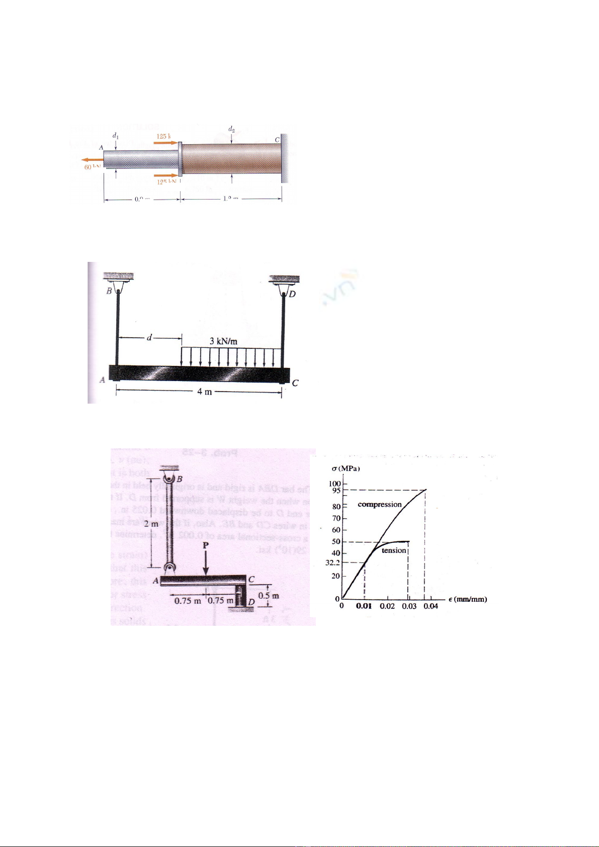
Two solid cylindrical rods AB and
BC are welded together at B and
loaded as shown (Fig. 1).
Knowing that the everage normal
stress must not exceed 150 MPa
in either rod, determine the
smallest allowable values of the
the diameters d1 and d2.
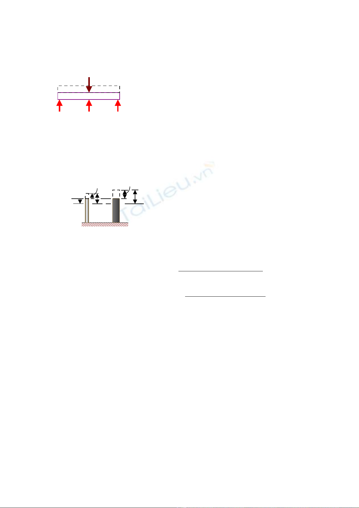
Exercise 2:
The uniform beam is
supported by two rods AB
and CD that have cross-
sectional areas of 10 mm2
and 15 mm2, respectively
(Fig. 2). Determine the
position d of the
distributed load so that
the average normal stress
in each rod is the same
Exercise 3:
Fig.3a Fig.3b
The stress-strain diagram for a polyester resin is given in the figure
3b. If the rigid beam is supported by a strut AB and post CD, both
made from this material, and subjected to a load of P = 80 kN
(Fig.3a), determine the angle of tiltof the beam when the load is
applied. The diameter of the strur is 40 mm and the diameter of the
post is 80 mm.
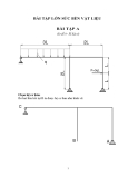
Exercise 4:
Fig. 1
Fig.2
125kN
125kN
60kN
0.9m 1.2m
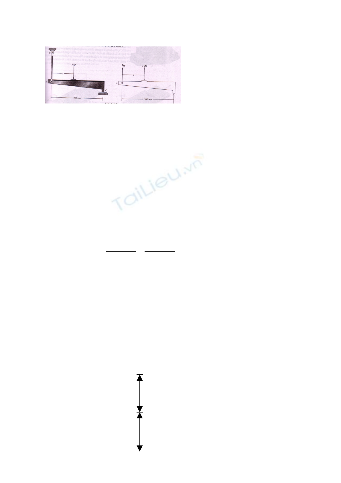
Member AC is subjected to
a vertical force of 3 kN.
Determine the position x of
this force so that the
compressive stress at C is
equal to the tensile stress
in the tie rod AB (Fig.4a).
The rod has a cross
sectional area of 400 mm2
and the contact area at C is
650 mm2.
Solution
Internal loading. The free body diagram for member AC is shown
in Fig. (4b). There are three unknowns, namely, FAB, FC, and x. The
equilibrium of AC will give:
( ) ( )
(1)
+ (2)
y AB C
AC
F 0 F F 3000N 0
M 0 - 3000N (x) F 200m m 0
+ ↑ = ⇒ + − =
= ⇒ + =
∑
∑
∑
Average Normal Stress. A necessary third equation can be written
that requires the tensile stress in the bar AB and the compressive
stress at C to be equivalent: i.e.,
( )
3
CAB A B
C
2 2
F
FF 1.625F
400 m m 650 m m
σ = = → =
Substituting (3) into Eq. 1, solving for FAB then solving for FC, we
obtain:
AB C
F 1143 N; F 1857 N= =
The position of the applied load is determined from Eq. 2.: x = 124
mm
Note that 0 < x < 200 mm, as required.
Exercise 5:
The steel column is used to support
the symmetric loads from the two
floors of a building (Fig.5).
Determine the loads P1 and P2 if A
moves downward 3 mm and B
moves downward 2 mm when the
loads are applied. The column has a
cross-sectional area of 645 mm2. Est
= 200 Gpa.
Fig.4
F
Fig.5
3,6
m
3,6m
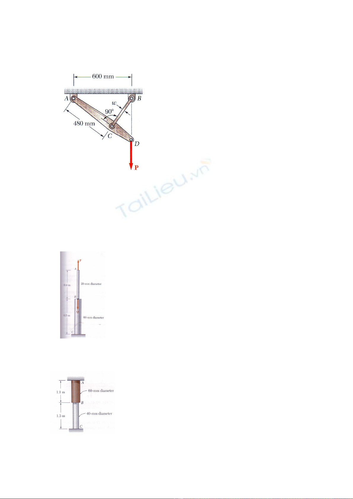
Exercise 6:
Link BC is 6 mm thick, has a
width w = 25 mm, and is made of
a steel of 480-MPa ultimate
strength in tension (Fig.6). What
was the safety factor used if the
structure shown was designed to
support a 16-kN load P?
Exercise 7:
In the figure 6 of the precedent exercise, suppose that link BC
is 6 mm thick and is made of a steel with a 450-MPa ultimate strength
in tension. What should be its width w if the structure shown is
beeing designed to support a 20-kN load P with a factor of safety of
3?
Exercise 8:
Both portions of the rod ABC are made of an
aluminum for which E = 70 Gpa (Fig.7). Knowing
that the magnitude of P is 4 kN. Determine:
(a) the value of Q so that the deflection at A is
zero;
(b) the corresponding deflection of B;
Fig.7
Exercise 9:
A rod consisting of two cylindrical portions AB
and BC is restrained at both ends. Portion AB
is made of brass (Eb = 105 GPa, αb = 20.9 x 10-
6/0C) and portion BC is made of aluminum (Ea
= 72 GPa, αa = 23.9 x 10⁻⁶/0C) (Fig.8). Knowing
that the rod is initially unstressed, determine
(a) the normal stresses induced in portions AB
and BC by a temperature rise of 420C; (b) the
corresponding deflection of point B.
Fig.6
Fig.8
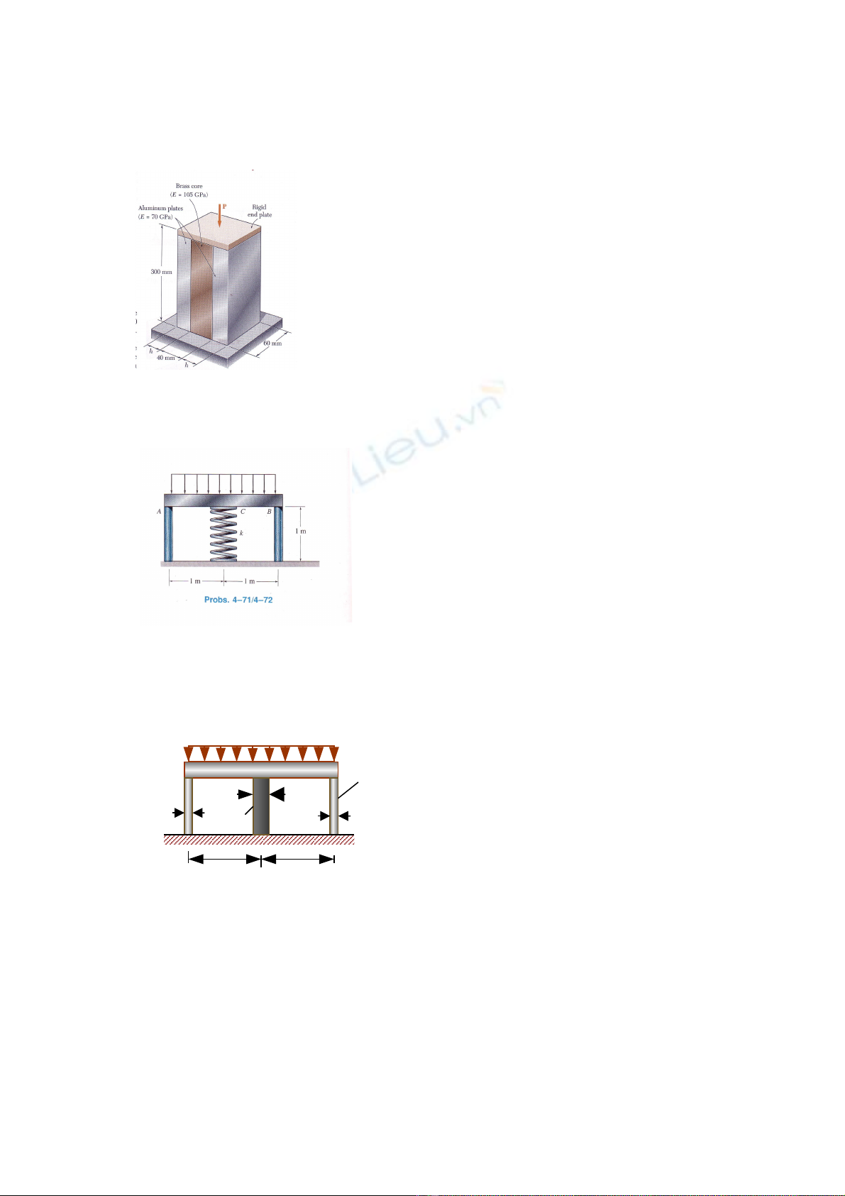
Exercise 10:
A axial centric force of magnitude P =
450 kN is applied to the composite
block shown by means of a rigid end
plate (Fig.9). Knowing that h = 10 mm,
determine the normal stress in (a) the
brass core, (b) the aluminum plate
Exercise 11:
The rigid bar is supported by the two
short white spruce wooden posts and a
spring. If each of the posts has an
unloaded length of 1 m and a cross-
sectional area of 600 mm2 , and the
spring has a stiffness of k = 2 MN/m
and an unstretched length of 1.02 m,
determine the vertical displacement of
A and B after the load is applied to the
bar
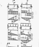
Exercise 12
The rigid bar shown in the figure is
fixed to the top of the three posts
made of steel and aluminum. The
posts each have a length of 250
mm when no load is applied to the
bar and the temperature is T1 =
200C. Determine the force
supported by each post if the bar is
subjected to a uniform distributed
load of 150 kN/m and the
temperature is raised to T2 = 800C.
The diameter of each post and its
material properties are listed in the
figure.
Fig.9
Fig.10
40m
m
40m
m
60mm
150kN/m
300mm 300mm
Steel
Steel
Est = 200 Gpa
αst = 12(10-6)/0C
Al.
Aluminum
EAl = 70 Gpa
αst = 23(10-6)/0C
Fig. 11
Solution
Equilibrium:
( )
1) (
3
y st Al
F 0; 2N N -90 10 0+ ↑ = → + =
∑
Compatibility: Due to load, geometry, and material symmetry, the
top of each post is displaced by an equal amount. Hence:
( )
( )
st Al
2+ ↓ δ = δ
The final position of the top of each post is equal to its
displacement caused by temperature, plus its displacement caused
by the internal axial force.
( )
( ) ( )
(3)
st st st
T N
+ ↓ δ = − δ + δ
( )
( ) ( )
(4)
Al A l Al
T N
+ ↓ δ = − δ + δ
Introducing into (2) gives:
( ) ( )
( ) ( )
st st Al A l
T N T N
− δ + δ = − δ + δ
(5)
Using Eqs. (2) – (5) , we get:
( ) ( )
( ) ( )
( )
( )
( ) ( )
( ) ( )
( )
( )
st
-6 0 0 0
29 2
Al
-6 0 0 0
29 2
N 0.250m
- 12 10 / C 80 C - 20 C 0.250m +p 0.02m 200 10 N/m
N 0.250m
=- 23 10 / C 80 C - 20 C 0.250m +p 0.03m 70 10 N/m
or
( )
3
st Al
N =1.270N -165.9 10
(6)
Solving (1) and (6) simultaneously yields:
Nst = - 14.6 kN NAl = 119 kN
The negative value of Nst indicate that this force acts opposite to that
shown in figure. In other words, the steel posts are in tension and the
aluminum post is in compression.
90
kN
Nst Nst
NAl
(δst)
T
(δst)
N
(δAl)T
(δAl)N
Final position
Initial
position


![Gia Công & Lắp Đặt Cốt Thép: Kỹ Thuật Xây Dựng Bê Tông [Chuẩn Nhất]](https://cdn.tailieu.vn/images/document/thumbnail/2026/20260531/alfredodistefano10/135x160/58891780257145.jpg)
![Gia Công Ván Khuôn: Lắp Dựng, Tháo Dỡ và Kỹ Thuật Xây Dựng [Chi Tiết A-Z]](https://cdn.tailieu.vn/images/document/thumbnail/2026/20260531/alfredodistefano10/135x160/4261780257147.jpg)

![Giáo Trình Công Tác Xây Dựng: Kỹ Thuật và Vật Liệu Xây Dựng [A-Z]](https://cdn.tailieu.vn/images/document/thumbnail/2026/20260531/alfredodistefano10/135x160/9351780261637.jpg)


%20--%3e%3cdefs%3e%3cstyle%3e%20.st0%20{%20fill:%20%23fff;%20}%20.st1%20{%20fill:%20%237800fa;%20}%20%3c/style%3e%3c/defs%3e%3cpath%20class='st1'%20d='M117.78,12.18H43.11c2.9,3.47,4.65,7.94,4.65,12.82,0,5.6-2.3,10.66-6.01,14.29h76.02l7.22-13.56-7.22-13.56Z'/%3e%3cg%3e%3cpath%20class='st0'%20d='M53.58,26.17h-.59v-1.46h.59v-4.96h2.83c1.78,0,2.67.94,2.67,2.82v5.76c0,1.87-.89,2.81-2.67,2.81h-2.83v-4.96ZM55.36,21.37v3.34h1.1v1.46h-1.1v3.34h1.01c.61,0,.91-.37.91-1.1v-5.93c0-.74-.3-1.1-.91-1.1h-1.01Z'/%3e%3cpath%20class='st0'%20d='M65.99,31.14h-1.8l-.31-2.07h-2.19l-.31,2.07h-1.64l1.82-11.39h2.62l1.82,11.39ZM65.28,18.04c-.25.46-.51.77-.75.94-.21.15-.47.22-.79.22-.26,0-.57-.07-.92-.22l-.38-.15c-.14-.05-.26-.07-.37-.07-.3,0-.53.18-.71.54l-.91-.68c.25-.46.51-.77.75-.94.21-.14.48-.21.79-.21.26,0,.57.07.92.21l.38.15c.14.05.26.07.37.07.3,0,.53-.18.71-.54l.91.68ZM61.91,27.52h1.73l-.87-5.76-.87,5.76Z'/%3e%3cpath%20class='st0'%20d='M74.53,26.89v1.52c0,1.91-.89,2.86-2.67,2.86s-2.67-.95-2.67-2.86v-5.93c0-1.91.89-2.86,2.67-2.86s2.67.95,2.67,2.86v1.11h-1.69v-1.22c0-.75-.31-1.12-.93-1.12s-.93.37-.93,1.12v6.15c0,.74.31,1.11.93,1.11s.93-.37.93-1.11v-1.63h1.69Z'/%3e%3cpath%20class='st0'%20d='M81.4,31.14h-1.8l-.31-2.07h-2.19l-.31,2.07h-1.64l1.82-11.39h2.62l1.82,11.39ZM75.9,19.2l1.52-1.91h1.71l1.51,1.91h-1.61l-.76-.95-.75.95h-1.61ZM77.32,27.52h1.73l-.87-5.76-.87,5.76ZM83.1,15.99l-1.76,1.91h-1.26l1.17-1.91h1.86Z'/%3e%3cpath%20class='st0'%20d='M84.86,19.75c1.78,0,2.67.94,2.67,2.82v1.48c0,1.87-.89,2.81-2.67,2.81h-.85v4.28h-1.79v-11.39h2.64ZM84.01,21.37v3.86h.85c.58,0,.87-.36.87-1.08v-1.71c0-.71-.29-1.07-.87-1.07h-.85Z'/%3e%3cpath%20class='st0'%20d='M93.51,19.75c1.78,0,2.67.94,2.67,2.82v1.48c0,1.87-.89,2.81-2.67,2.81h-.85v4.28h-1.79v-11.39h2.64ZM92.66,21.37v3.86h.85c.58,0,.87-.36.87-1.08v-1.71c0-.71-.29-1.07-.87-1.07h-.85Z'/%3e%3cpath%20class='st0'%20d='M98.8,31.14h-1.79v-11.39h1.79v4.88h2.03v-4.88h1.83v11.39h-1.83v-4.88h-2.03v4.88Z'/%3e%3cpath%20class='st0'%20d='M105.36,24.55h2.46v1.62h-2.46v3.34h3.09v1.63h-4.88v-11.39h4.88v1.63h-3.09v3.18ZM108.17,17.29l-1.76,1.91h-1.26l1.17-1.91h1.86Z'/%3e%3cpath%20class='st0'%20d='M112.2,19.75c1.78,0,2.67.94,2.67,2.82v1.48c0,1.87-.89,2.81-2.67,2.81h-.85v4.28h-1.79v-11.39h2.64ZM111.35,21.37v3.86h.85c.58,0,.87-.36.87-1.08v-1.71c0-.71-.29-1.07-.87-1.07h-.85Z'/%3e%3c/g%3e%3ccircle%20class='st1'%20cx='25'%20cy='25'%20r='20'/%3e%3cpath%20class='st0'%20d='M32.78,19.27c2.92,0,4.43,2.55,5.28,5.33l.71,2.17c.14.38-.33.75-.71.75h-5.61c.19-.33.24-.71.09-1.08l-.75-2.45c-.43-1.32-.99-2.64-1.79-3.77.75-.57,1.65-.94,2.78-.94h0ZM25,18.38c3.25,0,4.9,2.78,5.89,5.89l.76,2.45c.14.42-.33.8-.8.8h-11.69c-.42,0-.94-.38-.8-.8l.75-2.45c.99-3.11,2.64-5.89,5.89-5.89h0ZM25,11.35c1.74,0,3.11,1.37,3.11,3.11s-1.37,3.11-3.11,3.11-3.11-1.41-3.11-3.11,1.41-3.11,3.11-3.11h0ZM17.27,19.27c1.08,0,1.98.38,2.73.94-.8,1.13-1.37,2.45-1.74,3.77l-.8,2.45c-.14.38-.05.75.09,1.08h-5.56c-.42,0-.9-.38-.75-.75l.71-2.17c.9-2.78,2.41-5.33,5.33-5.33h0ZM17.27,12.91c1.51,0,2.78,1.27,2.78,2.83s-1.27,2.83-2.78,2.83-2.83-1.27-2.83-2.83,1.27-2.83,2.83-2.83h0ZM32.78,12.91c1.56,0,2.78,1.27,2.78,2.83s-1.23,2.83-2.78,2.83-2.83-1.27-2.83-2.83,1.27-2.83,2.83-2.83h0ZM27.07,28.56v.09c0,.57-.24,1.08-.61,1.46h0v.05c-.38.33-.9.57-1.46.57s-1.08-.24-1.46-.61h0c-.38-.38-.61-.9-.61-1.46v-.09h1.41v.09c0,.19.05.38.19.47v.05c.09.09.28.19.47.19s.38-.09.47-.19v-.05c.14-.09.24-.28.24-.47t-.05-.09h1.41ZM30.99,28.56v.09c0,1.65-.66,3.16-1.74,4.24-1.08,1.08-2.59,1.79-4.24,1.79s-3.16-.71-4.24-1.79l-.05-.05c-1.04-1.08-1.7-2.55-1.7-4.2v-.09h1.41v.09c0,1.27.47,2.4,1.27,3.25h.05c.85.85,1.98,1.37,3.25,1.37s2.4-.52,3.25-1.37c.85-.8,1.37-1.98,1.37-3.25v-.09h1.37ZM34.99,28.56v.09c0,2.78-1.13,5.28-2.92,7.07-1.79,1.79-4.29,2.92-7.07,2.92s-5.23-1.13-7.07-2.92c-1.79-1.79-2.92-4.29-2.92-7.07v-.09h1.41v.09c0,2.4.94,4.53,2.5,6.08,1.56,1.56,3.72,2.5,6.08,2.5s4.52-.94,6.08-2.5c1.56-1.56,2.5-3.68,2.5-6.08v-.09h1.41Z'/%3e%3c/svg%3e)