EURASIP Journal on Applied Signal Processing 2004:9, 1299–1307 c(cid:1) 2004 Hindawi Publishing Corporation
A Combined Antenna Arrays and Reverse-Link Synchronous DS-CDMA System over Frequency-Selective Fading Channels with Power Control Error
Yong-Seok Kim Communication System Lab., School of Electrical and Electronics Engineering, Yonsei University, 134 Sinchon-dong, Seodaemun-gu, Seoul 120-749, Korea Email: dragon@yonsei.ac.kr
Seung-Hoon Hwang Standardization and System Research Group, Mobile Communication Technology Research Laboratory, LG Electronics, 533 Hogye-dong, Dongan-gu, Anyang-shi, Kyungki-do, Korea
School of Electronics and Computer Sciences, University of Southampton, Highfield, Southampton, SO17 1BJ, UK Email: shwang@ieee.org
Hyo-Yol Park Communication System Lab., School of Electrical and Electronics Engineering, Yonsei University, 134 Sinchon-dong, Seodaemun-gu, Seoul 120-749, Korea Email: seahog@commsys.yonsei.ac.kr
Keum-Chan Whang Communication System Lab., School of Electrical and Electronics Engineering, Yonsei University, 134 Sinchon-dong, Seodaemun-gu, Seoul 120-749, Korea Email: kcwhang@yonsei.ac.kr
Received 26 May 2003; Revised 28 January 2004
An improved antenna array (AA) has been introduced, in which reverse-link synchronous transmission technique (RLSTT) is incorporated to effectively make better an estimation of covariance matrices at a beamformer-RAKE receiver. While RLSTT is effective in the first finger at the RAKE receiver in order to reject multiple-access interference (MAI), the beamformer estimates the desired user’s complex weights, enhancing its signal and reducing cochannel interference (CCI) from the other directions. In this work, it is attempted to provide a comprehensive analysis of user capacity which reflects several important factors such as the shape of multipath intensity profile (MIP), the number of antennas, and power control error (PCE). Theoretical analysis, confirmed by the simulations, demonstrates that the orthogonality provided by employing RLSTT along with AA may make the DS-CDMA system insensitive to the PCE even with fewer numbers of antennas.
Keywords and phrases: antenna arrays, reverse-link synchronous DS-CDMA, frequency-selective fading channel, power control error.
1. INTRODUCTION
multiusers, and intersymbol interference (ISI) which arises from the existence of different transmission paths. A promis- ing approach to increase the system capacity is the use of spa- tial processing with an antenna array (AA) at base station (BS) [1, 2, 3, 4, 5, 6]. Generally, the AA system consists of spatially distributed antennas and a beamformer which gen- erates a weight vector to combine the array output. Several al- gorithms have been proposed in the spatial signal processing DS-CDMA systems exhibit a user capacity limit in the sense that there exist a maximum number of users that can simul- taneously communicate over multipath fading channels and maintain a specified level of performance per user. This lim- itation is caused by cochannel interference (CCI) which in- cludes both multiple-access interference (MAI) between the
4πde cos θ λ
2πde cos θ λ
1300 EURASIP Journal on Applied Signal Processing
θ
de
de
de
4th element
3rd element
2nd element
1st element
to design the weights in the beamformer. For example, a new space-time processing framework for the beamforming with AA in DS-CDMA has been proposed in [2], where a code- filtering approach was used in each receiving antenna in or- der to estimate the optimum weights in the beamformer.
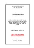
Figure 1: Antenna array model geometry.
(cid:5)
(cid:6)
(cid:5)
(cid:6)
(cid:2)
L(k)−1(cid:4)
N = T/Tc. We assume, for simplicity, that Tg equals Tc. The complex lowpass impulse response of the vector channel as- sociated with the kth user may be written as [3]
(cid:3) ,
l=0
exp V (2) δ hk(τ) = β(k) l jϕ(k) l θ(k) l τ − τ(k) l For a terrestrial mobile system, reverse-link synchronous transmission technique (RLSTT) has been proposed to re- duce interchannel interference over a reverse link [7]. In the RLSTT, the synchronous transmission in the reverse link can be achieved by adaptively controlling the transmission time in each mobile station (MS). In a similar way to the closed- loop power control technique, the BS computes the time dif- ference between the reference time generated in the BS and the arrival time of the dominant signal transmitted from each MS, and then transmits timing control bits, which order MSs to “advance” or “delay” their transmission times. The consid- ered DS-CDMA system uses orthogonal reverse-link spread- ing sequences and the timing control algorithm that allows the main paths to be synchronized.
l
l
l
(cid:6)
=
(cid:5) θ(k) l
is the Rayleigh fading strength, ϕ(k) is its phase is the propagation delay. The kth user’s lth path where β(k) shift, and τ(k) array response vector is expressed as
(cid:9)
(cid:9)(cid:10)T
l
l
V (cid:7)
· · · exp
(cid:8) − j2πd cos θ(k) λ
(cid:8) − j2(M−1)πd cos θ(k) λ
. 1 exp
(3)
In this paper, an improved AA has been introduced, in which RLSTT is incorporated to effectively make better an es- timation of covariance matrices at a Beamformer-RAKE re- ceiver. While RLSTT is effective in the first finger at the RAKE receiver in order to reject MAI, the beamformer estimates the desired user’s complex weights, enhancing its signal and re- ducing CCI from the other directions. In this work, it is at- tempted to provide a comprehensive analysis of user capac- ity which reflects several important factors such as the shape of multipath intensity profile (MIP), the number of anten- nas, and power control error (PCE). Of particular interest are the trade-offs encountered among parameters such as the number of receiving antennas and PCE. The paper is orga- nized as follows. In Section 2, channel and system models are described. The AA system with RLSTT is introduced and its theoretical analysis is derived to investigate the trade-offs among the system parameters in Section 3. Section 4 shows numerical results mainly focusing on the system capacity. Fi- nally, a concluding remark is given in Section 5. Throughout this paper, we consider that the array geometry, which is the parameter of the antenna aperture gain, is a uni- form linear array (ULA) of M identical sensors in Figure 1. All signals from MS arrive at the BS AA with mean angle of arrival (AOA) θ(k) l which is uniformly distributed in [0, π). Assuming Rayleigh fading, the probability density function (pdf) of signal strength associated with the kth user’s lth propagation path, l = 0, 1, . . . , L(k) − 1, is presented as
(cid:6)2
(cid:6)
−
2. CHANNEL AND SYSTEM MODEL
,
(cid:5) β(k) l
= 2β(k) l Ω(k) l
(cid:5) β(k) l Ω(k) l
exp (4) p
(cid:17)∞ l=0
l
l with
(cid:1)
(cid:2)
(cid:3)
We consider a BPSK-modulated DS-CDMA system over a multipath fading channel. Assuming K active users (k = 1, 2, . . . , K), the low-pass equivalent signal transmitted by user k is presented as is the second moment of β(k)
= Ω(k)
for exponentially decaying MIP as , (1) where Ω(k) Ωl = 1, and we assume it is related to the second moment of the ini- tial path strength Ω(k) 0 s(k)(t) = 2Pkb(k)(t)g (k)(t)a(t) cos ωct + φ(k)
0 exp(−lδ),
(5) for 0 < l ≤ L(k) − 1, δ ≥ 0, Ω(k) l
where δ reflects the rate at which the decay of average path strength as a function of path delay occurs. Note that a more realistic profile model may be the exponential MIP.
The receiver is a coherent RAKE receiver with AA, where the number of fingers Lr is a variable less than or equal to L(k) which is the number of resolvable propagation paths as- sociated with the kth user. Perfect estimates of the channel where a(t) is a pseudonoise (PN) randomization sequence which is common to all the channels in a cell to maintain the CDMA orthogonality, g (k)(t) is an orthogonal channel- ization sequence, and b(k)(t) is user k’s data waveform. In (1), Pk is the average transmitted power of the kth user, ωc is the common carrier frequency, and φ(k) is the phase angle of the kth modulator to be uniformly distributed in [0, 2π). The orthogonal chip duration Tg and the PN chip interval Tc is related to data bit interval T through processing gain
1301 A Combined Antenna Arrays and Reverse-Link Synchronous DS-CDMA System
(cid:1)
(cid:5)
(cid:5)
(cid:6)
K(cid:4)
L(k)−1(cid:4)
√
parameters are assumed. The complex received signal is ex- pressed as From (7) and (8), the corresponding beamformer output for the lth path of interest user is
(cid:6) b(k)
= W(1)H l = ˆS(1)
l + ˆI (1)
· y(1) l l,mai + ˆI (1)
l,si + ˆI (1) l,ni,
(cid:3)
(cid:2)
l=0 (cid:6)
× g (k)
l
k=1 (cid:5) t − τ(k) l
=
(cid:1) Pλ1/2β(1)
l C(1,1)
ll
l
L(k)−1(cid:4)
K(cid:4)
(cid:21)
=
l j
(cid:22)
(cid:2)
j C(l,k) β(k) (cid:3)
(cid:2)
(cid:3)(cid:24)
(cid:3)
×
ˆz(1) l r(t) = 2P (11) λk t − τ(k) l θ(k) l (cid:6) cos β(k) l V (cid:5) a + n(t), ωct + ψ(k) t − τ(k) l where (6) b(1) 0 T, ˆS(1) l (cid:1) P/2 λk ˆI (1) l,mai
k=2 b(k) −1RWk1
j=0 τ(k) l j
(cid:2) Ψ(k) l j
(cid:1)
(cid:3)
L(1)−1(cid:4)
=
, cos + b(k) 0 τ(k) l j
(cid:22) b(1) −1RW11
j C(1,1) β(1)
l j
(cid:23)RW k1 (cid:2) τ(1) l j
j=0 j(cid:5)=l
(cid:3)(cid:24)
(cid:3) ,
Pλ1/2 ˆI (1) l,si
(cid:2) τ(1) l j
(cid:2) Ψ(1) l j
(cid:18)
(cid:23)RW 11 (cid:5)
(cid:6)
τ(1) l +T
=
cos + b(1) 0
τ(1) l
· n(t)g (1) (cid:2) (cid:6)
l
(cid:18)
(cid:6)
(cid:6)
(cid:2)
(cid:3)
τ(1) l +T
=
(cid:5) a
(cid:5) t−τ(1) l
l
τ(1) l l + I(1) = S(1)
l,mai + I(1)
l,si + I(1) l,ni.
= ψ(k) j
0 being the information bit to be detected, b(1) − τ(1) l
ˆI (1) l,ni t − τ(1) l (cid:3) where P is the average received power and ψ(k) is the phase of the lth path associated to the kth carrier. λk corresponds to the PCE of the kth user which is a random variable due to im- perfect power control [8]. We consider λk to be log-normally distributed with standard deviation σλk dB. In other words, λk = 10(x/10), where the variable x follows a normal distribu- tion. n(t) is an M × 1 spatially and temporally white Gaus- sian noise vector with a zero mean and covariance which is nI, where I is the M × M iden- given by E{n(t)nH (t)} = σ 2 tity matrix, σ 2 n is the antenna noise variance with η0/2, and the superscript H denotes the Hermitian-transpose operator. When the received signal is matched to the reference user’s code, the lth multipath matched filter output for the interest user (k = 1) can be expressed as cos W(1)H l (cid:5) × a dt, ωct + ψ(1) t − τ(1) l (12) cos r(t) · g (1) dt ωct + ψ(1) t−τ(1) l y(1) l
l,2
· V(θ(k)
l j
= I(1)
l,mai + I(1)
l,si + I(1)
l
(7)
l
l=0 β(1) Lr
· ˆz(1) l
l
When a reference signal is not available, a common crite- rion for optimizing the weight vectors and this criterion is to maximize the signal-to-interference plus noise ratio (SINR). In (7), u(1) l,ni is a total interference plus noise for the lth path of interest user. By solving the follow- ing problem, we can obtain the optimal weights to maximize the SINR [9]:
l(opt)
W(1) , (8)
= max W(cid:5)=0
l Ry yW(1) l RuuW(1)
l
W(1)H W(1)H
(cid:20) ,
where Ry y and Ruu are the second-order correlation matri- ces of the received signal subspace and the interference plus noise subspace, respectively. Here, Ruu can be estimated by the code-filtering approach in [2], which is presented as with b(1) −1 the = τ(k) − ψ(1) , and ψ(k) preceding bit, τ(k) . j l l j l j · · · w(1) W(1) l,1 w(1) = [w(1) l,M]T is the M × 1 weight vector for l = W(1)H the lth path of the first user. C(1,k) j ) rep- l resents the spatial correlation between the array response vector of the kth user at the jth multipath and the weight vector of the interest user at the lth path. RW and (cid:23)RW are Walsh-PN continuous partial cross-correlation functions de- (cid:25) τ 0 g (k)(t − τ)a(t − τ) · g (1)(t)a(t)dt and fined by RWk1(τ) = (cid:25) (cid:23)RW k1(τ) = T τ g (k)(t − τ)a(t − τ)g (1)(t)a(t)dt. From (11), we can obtain the Rake receiver output from MRC combin- (cid:17) ing ˆz(1) = and see that the outputs of the lth branch, l = 0, 1, . . . , Lr − 1, consist of four terms. The first term represents the desired signal component to be detected. The second term represents the MAI from (K − 1) other si- multaneous users in the system. The third term is the self- interference (SI) for the reference user. Finally, the last term is AWGN.
(9) Ruu = N Ry y 3. PERFORMANCE OF AA WITH RLSTT IN RAYLEIGH N − 1
(cid:19) Rrr − 1 N
FADING CHANNEL WITH PCE
where Rrr means the covariance matrix of the received sig- nal prior to RAKE. The solution corresponds to the largest eigenvalue (λmax) of the generalized eigenvalue problem in the matrix pair (Ry y, Ruu). Therefore, we can obtain the max- imum SINR when the weight vector W(1) l(opt) equals the prin- cipal eigenvector of the matrix pair, which is presented as
= λmax · Ruu · W(1)
l(opt)
l(opt).
(10) In our analysis, the evaluation is carried out for the case in which the arrival time of paths is modeled as synchronous in the first branch (i.e., for main paths) but as asynchronous in the rest of the branches (i.e., for multipaths). With the well- known Gaussian approximation, we model the MAI terms in the first branch and the other branches as a Gaussian process with variances equal to the MAI variances for l = 0 and for l ≥ 1, respectively. Extending the derived results in [7], the Ry y · W(1)
l
1302 EURASIP Journal on Applied Signal Processing
(cid:22)
(cid:24)2
(cid:22)
L(k)−1(cid:4)
(cid:28)
(cid:24)2 K(cid:4)
·
variance of MAI for l = 0, conditioned on the values of β(1) and λk, is At the output of the receiver, SNR may be written in a more compact form as γs:
! (2N −3)
" −1 λI
j ζ (1,k)2
0 j
·
= EbT(2N − 3) 12N(N − 1)
(cid:24)2
j=1
k=2
(cid:27) Lr, δ 6N(N − 1)
(cid:22) ζ (cid:9) · 0
(cid:22) β(1) l
(cid:17)
Lr −1 l=1
(cid:27) Lr, δ
(cid:28) λI
·
(cid:22)
Lr −1 l=1 (cid:24)2 β(1) l (cid:17)
(cid:24)2
L(k)−1(cid:4)
(cid:24)2 K(cid:4)
Lr −1 l=1
j ζ (1,k)2
(cid:22) β(1) l
l j
(cid:22)
= EbT(N − 1) 6N 2
(cid:17)
(cid:22) β(1) 0 (cid:24)2
(cid:24)2
j=0
k=2
!
(cid:28)
·
Ω(k) q (13) . λk β(1) 0 σ 2 mai,0 γs = β(1) 0 (cid:17) ζ 2 0 (cid:24)2 β(1) 0 + ζ (cid:9)· (cid:22) Similarly, the variance of MAI for l ≥ 1 is (N − 1)q + ζ 2 · (cid:24)2 3N 2 +ζ (cid:9) · Ω(k) ζ (cid:9) 0 , (14) λk σ 2 mai,l
Lr −1 l=1
" − 1 λ1
(cid:27) Lr, δ
·
(cid:22)
(cid:17)
(cid:24)2
(cid:24)2
=
l j
· (cid:22) β(1) 0 (cid:22) β(1) 0
Lr −1 l=1
(cid:24)2
· (cid:24)2
(cid:9)2 ·
·
(cid:9)2 0
·
Lr −1 l=1 (cid:22)
(cid:17)
(cid:24)2
(cid:22) β(1) 0 (cid:22) β(1) 0
Lr −1 l=1
(cid:22) β(1) l (cid:24)2 β(1) l (cid:20)
(cid:24)2
· (cid:24)2
·
(cid:22) β(1) 0
(cid:22) β(1) l
Lr −1 l=1
×
(cid:22)
(cid:24)2 L(1)−1(cid:4)
j ζ (1,1)2
l j
≈ Ebλ1T 4N
(cid:17)
j=0 j(cid:5)=l
= ζ 2
l j
+ ζ 2 · ζ 2 0 q + 2N ζ (cid:9) 0 + ζ (cid:9) · (cid:17) β(1) l β(1) l β(1) l −1 + ζ ζ + ζ (cid:9) 0 η0 2MΩ0Eb (cid:19) + ζ (cid:9) · (cid:17) λ1 ζ (cid:9) 0 where Eb = PT is the signal energy per bit, and ζ (1,k)2 E(cid:6){C(1,k) }2(cid:7) is the second-order characterization of the spa- l j tial correlation between the array response vector of the kth user at the jth multipath and the weight vector of interest user at the lth path, of which more detailed derivation is de- scribed in the appendix. The conditional variance of σ 2 si,l is approximated by [10]: , + ζ (cid:9) · Ω0 (19) Ω(1) (15) . σ 2 si,l β(1) l
l j
= ζ
(cid:22)
(cid:24)2
·
, is calculated as The variance of the AWGN term, conditioned on the value of β(1) l
= Tη0ζ (1,1)2 ll 4M
(16) . σ 2 ni,l β(1) l
(cid:26)
Lr −1 l=0 exp(−lδ) = 1 − exp(−Lrδ)/1 − where q(Lr, δ) = (cid:17) = Ω0. ζ (k,m)2 k=2 λk, and Ω(k) K exp(−δ), λI = 0 when 0 k (cid:5)= m or l (cid:5)= j for l = 0, ζ (k,m)2 = ζ 2 when k (cid:5)= m or l (cid:5)= j for l > 0, ζ (k,m)2 (cid:9)2 0 when k = m and l = j for l = 0, and l j ζ (k,m)2 (cid:9)2 when k = m and l = j for l > 0. In [11], the pdf = ζ l j (cid:17) K of λI = k=2 λk for K − 1 users is an approximately lognor- mal distribution, with the following logarithmic mean and variance, which is presented as (cid:7)
(cid:10)
(cid:27)
(cid:22)
Lr −1(cid:4)
(cid:28)2
(cid:24)2
(cid:28)
Therefore, the output of the receiver is a Gaussian random process with mean
=
−
(cid:27) λI
l=0
1√ (17) Us = exp , (20) β(1) l ζ (1,1) ll p Ebλ1T 2 2πσλI λI ln λI − mλI 2σ 2 λI
(cid:19)
(cid:20)
(cid:27)
(cid:28)
where
= ln
Lr −1(cid:4)
Lr −1(cid:4)
(cid:28)
and the total variance equal to the sum of the variance of all the interference and noise terms. From (13), (14), (15), and (16), we have exp , + σ 2 I 1 K − 1 K − 2 K − 1
= σ 2
mai,0 +
(cid:27) si,l + σ 2 σ 2 ni,l
(cid:19)
l=1
l=0
(cid:28)
(cid:27)
(21) mI = ln(K − 1) + m + σ 2 T σ 2 mai,l + σ 2 λI σ 2 λI 2
(cid:20) .
− 1 2
!
(cid:28)
(cid:24)2
= EbTΩ0
·
" − 1
(cid:22) β(1) 0
×
(cid:22)
(cid:17)
(cid:24)2
ln + exp σ 2 λI K − 2 K − 1 1 K − 1 (2N − 3) q λI ζ 2 0
(cid:28)
Lr −1 l=1
(cid:20)
(cid:22)
(cid:28)
!
(cid:17)
(cid:24)2
(cid:24)2
(cid:28)Lr −1(cid:4)
(cid:28)
(cid:27)
(cid:27)(cid:21)
·
=
" −1
(cid:27) Lr, δ
(cid:27) Lr, δ 12N(N − 1) (cid:28) (cid:27) λI ζ 2 · Lr, δ 6N 2 (cid:19) ζ 2 0
(cid:22) β(1) l
Lr −1 l=1
(cid:28) dx d y,
− y/Ω0
(cid:27) −x/Ωk exp
0
0
· 1 Ω0
k=1
(cid:20)
(cid:22)
(cid:24)2
(cid:24)2
(cid:9)2 ·
·
(cid:19) ζ
(cid:9)2 0
(cid:22) β(1) l
Lr −1 l=1
(N − 1)q β(1) l + Pl e This method is valid for a logarithmic standard deviation σλ less than 4 dB. To evaluate the average bit error probability, Pl e(λ1, λI ), conditioning on the values of λ1 and λI follows as (cid:27) λ1, λI (cid:18) ∞ (cid:18) ∞ q +ζ 2 · λ1 β(1) 0 exp Q γs πk Ωk + 4N (cid:17) η0 (22) β(1) 0 + . + ζ 4MEbΩ0
i=1,i(cid:5)=k(Ωk/(Ωk − Ωi)), (cid:25) ∞ x exp(−u2/2)du. The average bit error
where πk = ΠLr −1 i=1,i(cid:5)=k(xk/(xk − xi)) = ΠLr −1 √ Q(x) = (1/ 2π) (18)
10−1
10−1
10−2
10−2
10−3
10−3
R E B
R E B
10−4
10−4
10−5
10−5
0
5
15
20
0
5
15
20
10 Eb/N0 (dB)
10 Eb/N0 (dB)
Sync, PCE = 0 dB (analysis) Async, PCE = 0 dB (analysis) Sync, PCE = 0 dB (simulation) Async, PCE = 0 dB (simulation) Sync, PCE = 3 dB (analysis) Async, PCE = 3 dB (analysis) Sync, PCE = 3 dB (simulation) Async, PCE = 3 dB (simulation)
Sync, PCE = 0 dB (analysis) Async, PCE = 0 dB (analysis) Sync, PCE = 0 dB (simulation) Async, PCE = 0 dB (simulation) Sync, PCE = 3 dB (analysis) Async, PCE = 3 dB (analysis) Sync, PCE = 3 dB (simulation) Async, PCE = 3 dB (simulation)
(a)
(b)
A Combined Antenna Arrays and Reverse-Link Synchronous DS-CDMA System 1303
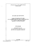
Figure 2: Analytical results versus simulation results. (Number of users = 12, M = 4, Lr = L(k) = 2, PCE = 0 and 3 dB.) (a) δ = 1.0, (b) δ = 0.2.
(cid:18) ∞
(cid:27)
(cid:27)√
−∞
−∞
(cid:27)√
(cid:28) , (cid:28)(cid:28)
probability Pe is calculated as (cid:18) ∞ exp 2σλ1 z1 + mλ1 Pl e Pe = 1√ π 1√ π in RAKE is assumed to be the same for all users and denoted by two. The decaying factor is considered as 1.0 or 0.2 for the exponential MIP. The sensor spacing is half of the carrier wavelength.
’
× exp
− z2 1
− z2 I
√
√
exp & 2σλI zI + mλI & ’ dz1 exp dzI , (23)
2σλ1 and zI = (ln λI − mλI )/
where z1 = (ln λ1 − mλ1 )/ 2σλI . This integration can be easily obtained by using the Hermite polynomial approach, which requires only summation and no integration [12]:
h(cid:4)
h(cid:4)
(cid:27)
(cid:27)√
(cid:28) ,
n=1
l=1
(cid:27)√
Figure 2 shows uncoded BER performance as a function of Eb/N0, when the number of users is twelve and the number of antennas is four in the exponential MIP. Two decay factors are considered, and both perfect power control (PCE = 0 dB) and imperfect power control (PCE = 3 dB) are assumed. The results confirm that the analytical results are well matched to the simulation results. It is noted that using RLSTT to- gether with AA may enhance the performance, since RLSTT tends to make better the estimation of covariance matrices for beamformer-RAKE receiver. exp wl 2σλ1 xn + mλ1 wnPl e Pe = 1 π (24)
(cid:28)(cid:28) .
exp 2σλI xl + mλI
4. NUMERICAL RESULTS
The BER curves are plotted as functions of the number of users in Figure 3 when Eb/N0 = 20 dB and power con- trol is perfect. The number of antennas is chosen among one, four, or eight. It is shown that AA with RLSTT demon- strates significant performance gain when the number of users increases, even though the performance improvement decreases when the number of antenna increases. For exam- ple, in the case of four antennas, while AA without RLSTT supports 60 users, AA with RLSTT supports more than 96 users at a BER of 10−3, showing an enhancement of 50%.
In this section, we have investigated the user capacity of AA system both with RLSTT and without RLSTT, considering several important factors such as the shape of MIP, the num- ber of antennas, and the PCE. In all evaluations, processing gain is assumed to be 128, and the number of paths and taps Figure 4 shows the BER system performance as a func- tion of the number of users, when M = 4, Eb/N0 = 20 dB,
10−1
10−1
10−2
10−2
10−3
10−3
R E B
R E B
10−4
10−4
10−5
10−5
10−6
10−6
12
24
36
48
60
72
84
96
12
24
36
48
60
72
84
96
Number of users
Number of users
M = 4 M = 8
M = 4 M = 8
with RLSTT without RLSTT M = 1
with RLSTT without RLSTT M = 1
(a)
(b)
1304 EURASIP Journal on Applied Signal Processing
Figure 3: BER versus number of users in AA with RLSTT and AA without RLSTT (Eb/N0 = 20 dB, M = 1, 4, and 8, Lr = L(k) = 2, PCE = 0 dB). (a) δ = 1.0, (b) δ = 0.2.
10−2
10−2
10−3
10−3
R E B
R E B
10−4
10−4
10−5
10−5
12
24
36
60
72
84
12
24
36
60
72
84
48 Number of users
48 Number of users
PCE = 2 dB PCE = 3 dB PCE = 4 dB
PCE = 2 dB PCE = 3 dB PCE = 4 dB
with RLSTT without RLSTT PCE = 0 dB PCE = 1 dB
with RLSTT without RLSTT PCE = 0 dB PCE = 1 dB
(a)
(b)
Figure 4: BER versus number of users in AA with RLSTT and AA without RLSTT (Eb/N0 = 20 dB, M = 4, Lr = L(k) = 2, PCE = 0, 1, 2, 3, and 4 dB). (a) δ = 1.0, (b) δ = 0.2.
and power control is imperfect. The curves are parameter- ized by different PCE values such as PCE = 0, 1, 2, 3, and 4[dB], and show that RLSTT makes DS-CDMA system with AA insensitive to the PCE and thus increases the achievable overall system capacity. At BER = 5 × 10⁻⁴, AA with RLSTT when PCE = 2 dB can support even greater number of users, about 35% more than AA without RLSTT when power con- trol is perfect (PCE = 0 dB), even though its capacity when PCE = 2 dB is degraded about 28% in comparison to the perfect power control.
100
90
90
80
80
70
70
60
60
50
50
40
40
s r e s u f o r e b m u N
s r e s u f o r e b m u N
30
30
20
20
10
10
0
0
0
0
1
2
3
1
2
3
PCE (dB)
PCE (dB)
with RLSTT without RLSTT
with RLSTT without RLSTT
M = 4 M = 8
M = 4 M = 8
(a)
(b)
A Combined Antenna Arrays and Reverse-Link Synchronous DS-CDMA System 1305
Figure 5: Number of users versus PCE in AA with RLSTT and AA without RLSTT (Eb/N0 = 20 dB, M = 4 and 8, Lr = L(k) = 2, BER = 10−4) (a) δ = 1.0 (b) δ = 0.2.
APPENDIX
SPATIAL CORRELATION STATISTICS
(cid:6) ;
From (10), we can obtain the optimal beamformer weight presented as
= ξ · R(k)−1
uu,l V
(cid:5) θ(k) l
= σ (k)2 s,l
(A.1) W(k) l
In Figure 5, the maximum allowable number of users to achieve BER of 10−4 is shown as a function of PCE when the number of antenna elements is four or eight. The fig- ure demonstrates while in eight-element AA without RLSTT PCE is required to keep less than 1 dB in order to achieve the user capacity of 50 users, AA with RLSTT may make loose the requirement to 3 dB. The figure can also be used to find the overall system capacity for a given PCE and the num- ber of antenna elements. These results, however, do not take into account effects such as coding and interleaving. Addi- tionally, it is apparent that RLSTT has superior performance and/or reduces the complexity of the system since AA with RLSTT with fewer numbers of antennas can obtain better performance than AA without RLSTT.
= I(k)
since ξ does not affect the SINR, we can set ξ = 1. When the total number of paths is large, a large code length yields R(k) ·I [2]. However, it means that the total undesired uu,l signal vector can be modeled as a spatially white Gaussian random vector. Here, σ (k)2 is the total interference-plus-noise s,l power. From (7), the total interference-plus-noise for the lth path of the kth user in the matched filter output is shown as 5. CONCLUSIONS
l,si + I(k)
l,mai + I(k) l,ni.
l,si + I(k)
(A.2) u(k) l
)
If we assume that the angles of arrival of the multipath com- ponents are uniformly distributed over [0, π), the total inter- ference vector I(k) l,mai will be spatially white [2, Chapter 6]. In this case, the variance of the undesired signal vector is calculated as
E
( u(k) l
· u(k)H l
(cid:6)
=
· I,
= σ (k)2 · I s,l (cid:5) mai,l + σ (k)2 σ (k)2
si,l + σ (k)2
ni,l
mai,l and σ (k)2
(A.3)
where σ (k)2 si,l are the noise variance of MAI and SI in one-dimension antenna system. For the RLSTT model [7], all active users are synchronous in the first branch. Therefore, In this paper, we presented an improved AA, in which RLSTT is incorporated to effectively make better an estimation of co- variance matrices at a beamformer-RAKE receiver, and inves- tigated the user capacity and the performance analysis which reflects several important factors such as the shape of mul- tipath intensity profile (MIP), the number of antennas, and power control error (PCE). The results show that the orthog- onality provided by employing RLSTT along with AA may make the DS-CDMA system insensitive to the PCE even with fewer numbers of antennas. Additionally, RLSTT has supe- rior performance and/or reduces the complexity of the sys- tem since AA with RLSTT with fewer numbers of antennas can obtain better performance than AA without RLSTT. The consideration of estimation technique such as diagonal load- ing employed in the proposed system may be an interesting issue for future study.
1306 EURASIP Journal on Applied Signal Processing
l
h have uniform distri-
+
*(cid:22)
(cid:24)2
(cid:28)
and θ(m) The mean angles of arrival θ(k) bution in [0, π) independently. So, we can obtain the different variance of the total interference- plus-noise for l = 0 and for l ≥ 1, conditions on the value of λk, respectively, expressed as follows:
(cid:27) λ1, λI
(cid:28)
!
(cid:19)
(cid:6)
π
π
" − 1
=
= EbTΩ0
l dθ(m)
h
(cid:5) θ(k) l
0
!
(cid:20)
0
M−1(cid:4)
E σ (k)2 s,0 CR(k,m) lh (cid:18) (cid:18) (2N − 3)λI dθ(k) A , θ(m) h
(cid:27) Lr, δ q 12N(N − 1) " (cid:28) (cid:27) − 1 Lr, δ q 4N
(cid:28)
(cid:27) λ1, λI
λ1 + + for l = 0, (i + 1)J0(π si)J0(−π si) η0 4EbΩ0
i=0 2(M−1)(cid:4)
=
(cid:28)
(cid:19)
(cid:27) Lr, δ
= EbTΩ0
i=M
(cid:28)
!
(cid:20)
σ (k)2 s,l + k (cid:5)= m or l (cid:5)= h, (2M − i − 1)J0(π si)J0(−π si),
" − 1
M2, k =m, l =h, λ1 + + for l ≥ 1. (A.9) (N − 1)λI q 6N 2 (cid:27) Lr, δ q 4N η0 4EbΩ0 (A.4)
where J0(x) is the zero-order Bessel function of the first kind.
= σ (k)−2
·V(θ(k) l
s,l
REFERENCES
[1] L. C. Godara, “Application of antenna arrays to mobile com- munications. II. Beam-forming and direction-of-arrival con- siderations,” Proceedings of the IEEE, vol. 85, no. 8, pp. 1195– 1245, 1997.
(cid:6)
(cid:5)
(cid:6)
Using the Hermite polynomial approach, we can evaluate the average total interference-plus-noise power per AA element. With these assumptions, the optimal beamformer weight of the kth user at the lth multipath can be shown to be W(k) ). Therefore, between the array response l vector of the mth user at the hth multipath and the weight vector of the kth user’s lth path, the spatial correlation can be expressed as
[2] A. F. Naguib, Adaptive antennas for CDMA wireless networks, Ph.D. dissertation, Electrical Engineering Department, Stan- ford University, Stanford, Calif, USA, 1996.
(cid:5) θ(m) h
=
= CR(k,m) lh σ (k)2 s,l
VH θ(k) l , (A.5) C(k,m) lh V σ (k)2 s,l
where
[3] G. Raleigh, S. N. Diggavi, A. F. Naguib, and A. Paulraj, “Char- acterization of fast fading vector channels for multi-antenna communication systems,” in Proc. 28th Asilomar Conference on Signals, Systems and Computers, vol. 2, pp. 853–857, Pacific Grove, Calif, USA, October–November 1994.
(cid:5)
(cid:6)(cid:6)
(cid:5)
(cid:5)
M−1(cid:4)
=
(cid:6)(cid:6) ,
− jπ si cos
(cid:5) θ(k) l
i=0
exp exp jπ si cos CR(k,m) lh θ(m) h
. s = 2d λ
[4] A. Stephenne and B. Champagne, “Effective multi-path vector channel simulator for antenna array systems,” IEEE Trans. Vehicular Technology, vol. 49, no. 6, pp. 2370–2381, 2000. [5] J. S. Thompson, P. M. Grant, and B. Mulgrew, “Smart antenna arrays for CDMA systems,” IEEE Personal Communications, vol. 3, no. 5, pp. 16–25, 1996.
(A.6)
The second-order characterization of the spatial correla-
[6] A. J. Paulraj and C. B. Papadias, “Space-time processing for wireless communications,” IEEE Signal Processing Magazine, vol. 14, no. 6, pp. 49–83, 1997.
+
*(cid:22)
(cid:24)2
+
*(cid:22)
tion is calculated as
(cid:24)2
E
[7] E.-K. Hong, S.-H. Hwang, K.-J. Kim, and K.-C. Whang, “Syn- chronous transmission technique for the reverse link in DS- CDMA terrestrial mobile systems,” IEEE Trans. Communica- tions, vol. 47, no. 11, pp. 1632–1635, 1999.
=
= E
, (A.7) ζ (k,m)2 lh C(k,m) lh CR(k,m) lh σ (k)4 s,l
[8] W. Ye and A. M. Haimovich, “Performance of cellular CDMA with cell site antenna arrays, Rayleigh fading, and power con- trol error,” IEEE Trans. Communications, vol. 48, no. 7, pp. 1151–1159, 2000.
(cid:6)
(cid:24)2
(cid:5) = A
(cid:6)
(cid:5)
(cid:6)
M−1(cid:4)
=
− jπ si cos θ(m)
l
h
where (cid:22) CR(k,m) lh , θ(m) θ(k) h l (cid:5) exp (i + 1) exp jπ si cos θ(k)
[9] J. Litva and T.-K. Lo, Digital Beamforming in Wireless Commu- nications, Artech House Publisher, Boston, Mass, USA, 1996. [10] T. Eng and L. B. Milstein, “Coherent DS-CDMA performance in Nakagami multipath fading,” IEEE Trans. Communications, vol. 43, no. 234, pp. 1134–1143, 1995.
i=0
[11] R. Prasad, CDMA for Wireless Personal Communications,
(cid:5)
(cid:6)
2(M−1)(cid:4)
Artech House Publisher, Boston, Mass, USA, 1996.
l
i=M
(cid:5)
+ (2M − i − 1) exp jπ si cos θ(k)
[12] M. Abramowitz and I. A. Stegun, Handbook of Mathematical Functions, National Bureau of Standards Applied Mathemat- ics Series, Dover Publications, New York, NY, USA, 1965.
× exp
− jπ si cos θ(m)
(cid:6) .
h
(A.8)
A Combined Antenna Arrays and Reverse-Link Synchronous DS-CDMA System 1307