
Compression of line-drawing images
using vectorizing and feature-based filtering
Pasi Fränti, Eugene I. Ageenko
Department of Computer Science, University of Joensuu
P.O. Box 111, FIN-80101 Joensuu, FINLAND
Alexander Kolesnikov, Igor O. Chalenko
Institute of Automation and Electrometry, Russian Academy of Sciences
Pr-t Ak. Koptyuga, 1, Novosibirsk-90, 630090, RUSSIA
Abstract:
A three-stage method for compressing bi-level line-drawing
images is proposed. In the first stage, the raster image is
vectorized using a combination of skeletonizing and line
tracing algorithm. A feature image is then reconstructed
from the extracted vector elements. In the second stage, the
original image is processed by a feature-based filter for
removing noise near the borders of the extracted line
elements. This improves the image quality and results in
more compressible raster image. In the final stage, the
filtered raster image is compressed using the baseline JBIG
algorithm. For a set of test images, the method achieves
a compression ratio of 40:1, in comparison to 32:1 of the
baseline JBIG.
Keywords: image compression, JBIG, raster-to-vector
conversion, context modeling, feature based filtering.
1. INTRODUCTION
Lossless compression of bi-level images has been well
studied in the literature and several standards already exist
[1]. In the baseline JBIG the image is coded pixel by pixel
in scan raster order using context-based probability model
and arithmetic coding [2]. The combination of already
coded neighboring pixels defines the context. In each
context the probability distribution of the black and white
pixels are adaptively determined. The current pixel is then
coded by QM-coder [3], the binary arithmetic coder
adopted in JBIG.
The baseline JBIG achieves compression ratios from 10 to
50 for typical A4-size images. The pixelwise dependencies
are well utilized and there is no much room for
improvement. Remarkable improvement has been achieved
only by specializing to some known image types and
exploiting global dependencies, or extending the methods
to lossy compression. For example, the methods in [4, 5]
includes pattern matching technique to extract symbols
from text images. The compressed file consists of bitmaps
of the library symbols coded by a JBIG-style compressor,
location of the extracted marks as offsets, and a pixelwise
coding of the matched symbols using two-layer context
template.
We study similar approach for line-drawing images by
utilizing global dependencies in images such as engineering
drawings, cartographic maps, architectural and urban plans,
schemes, and circuits (radio electrical and topological).
These kinds of images contain mainly of straight-line
elements. Global information can be gathered by extracting
line features from the image and utilizing them in the
compression of the raster image.
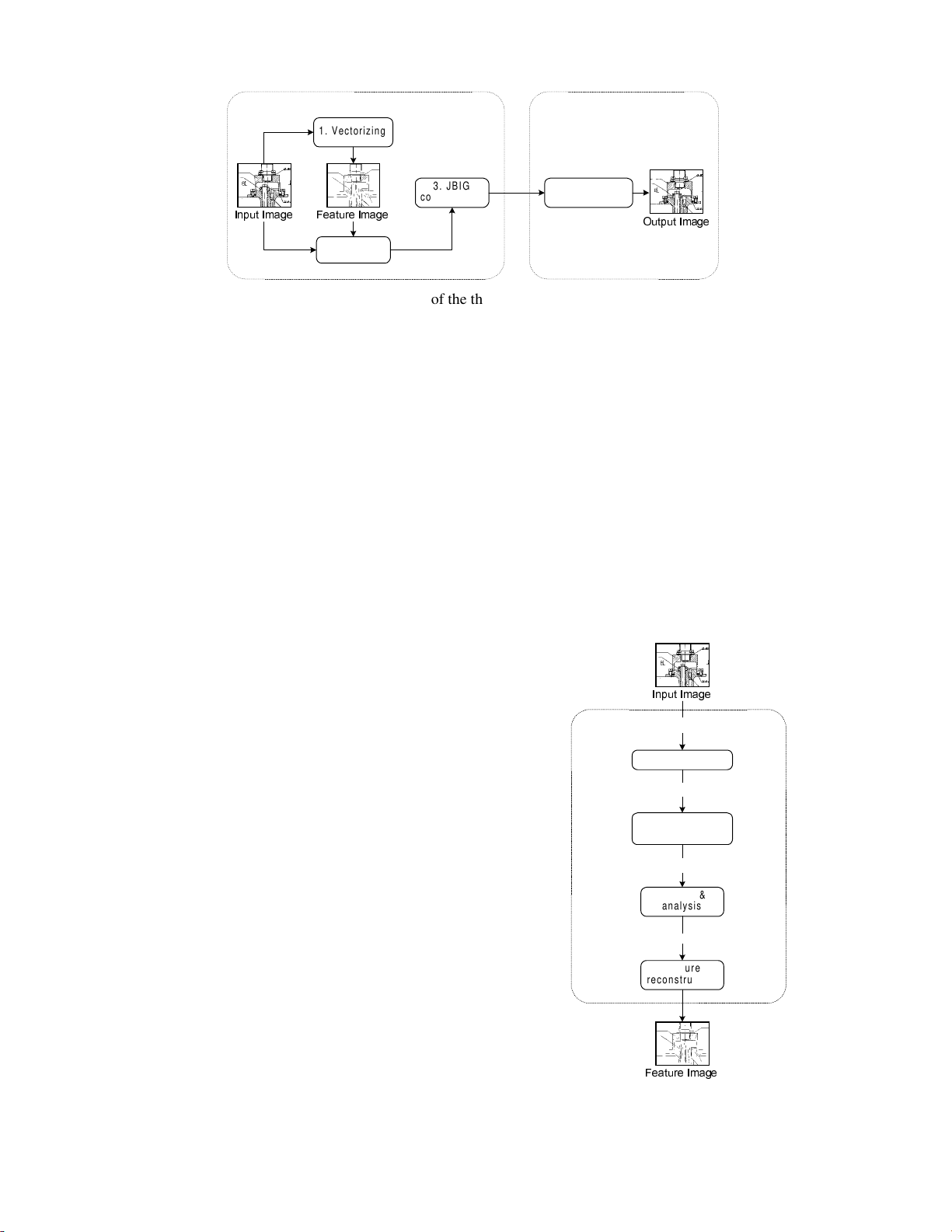
We propose a three-stage compression method as outlined
in Figure 1. In the first stage (vectorizing), vector elements
are extracted from the image using raster-to-vector
conversion. Equal size feature image is created from the
extracted line segments to approximate the input image. In
the second stage (filtering), the original raster image is
preprocessed by a feature-based filtering for improving
image quality. The feature image is used as a semantic
model of the image, consisting of non-local information
from the image, which cannot be utilized using local spatial
filters. In the third stage (compression), the filtered image is
compressed by the baseline JBIG. The feature file is used
only in the compression phase and therefore it is not needed
to store in the compressed file.
The feature extraction and filtering are considered as
preprocessing and they are invisible in the decompression
phase. The method uses standard image compression
component – the baseline JBIG. The resulting output files
are therefore standard JBIG files and the decompression is
exactly the same as the baseline JBIG. The method can thus
be easily integrated into existing compression systems. The
vectorizing and filtering parts can be implemented as
optional components, and used on-demand only.
International Conference Graphicon 1998, Moscow, Russia, http://www.graphicon.ru/
The method is near-lossless because only isolated groups of
noise pixels can be inverted. Moreover, undetected objects
(such as text characters) are untouched allowing their
lossless reconstruction. Uncontrolled loss of image quality
cannot therefore appear.
The vectorizing is an essential part of the new method but
the method itself is independent on the chosen vectorizing
component. The quality of the vectorizing affects only on
the amount of compression improvement that can be
achieved. The quality of the output image is controlled by
the filtering method. The details of the three stages are
discussed next in the following sections.
2. FEATURE EXTRACTION USING
VECTORIZING
The vectorizing process is outlined in Figure 2. We apply
the method described in [6]. The motivation is to find rigid
fixed-length straight lines from the image. Each line
segment is represented as its two end-points and as the
width of the line. A feature image is then reconstructed
from the line segments and utilized in the filtering. The
vector features are not stored in the compressed files but the
vectorizing is considered as an intelligent preprocessing
stage. The details of the vectorizing process are described
in the following subsections.
2.1 Skeletonization
The black-and-white raster image is processed by a distance
transform (defined by 4-connectivity). The resulting width-
labeled image is then skeletonized using the algorithm in
[7]. It proceeds the pixels layer by layer starting from
contour pixels (pixels with distance value 1). The 3×3
neighborhood of each pixel is checked. The pixels
satisfying one of the so-called “multiplicity condition” are
marked as skeletal pixels. The process is then iterated for
the pixels of the next layer (pixels with distance value 2)
and so on until all layers are processed. The result of the
algorithm is a width-labeled skeletal image. Fast and
memory efficient implementation of the algorithm was
constructed using the ideas presented in [8].
2.2 Extraction of elementary vectors
Vector primitives are extracted from the skeletal image
using a fast and simple line-tracing algorithm. We trace all
branches of the skeleton, one pixel at a time, from one
delimiter (line end or crossroad) to another. At this stage,
no digression from the current direction is allowed during
the traversal. The length of the vector primitives is limited
to be at most five pixels. The extracted lines are stored as
single vector elements using the average width of the
skeletal pixel as the line width.
The actual implementation uses LUT and cellular logic.
Each pixel is processed by examining its neighborhood in
a 3×3 window. An index is constructed from neighboring
pixel values and a precalculated look-up table (of size 29) is
2. Filtering
2XWSXW ,PDJH
)HDWXUH ,PDJH
1. Vectorizing
3. JBIG
compression JBIG
decompression
COMPRESSION DECOMPRESSION
,QSXW ,PDJH
Figure 1: Block diagram of the three-stage compression method.
Vector element
extraction
,QSXW ,PDJH
Skeletonization
VECTORIZING
)HDWXUH ,PDJH
Pruning &
analysis
Final vectors elements
Feature
reconstruction
Elementary vectors
Skeletal pixels
Figure 2: Block diagram of the vectorizing.
International Conference Graphicon 1998, Moscow, Russia, http://www.graphicon.ru/
accessed. The current direction is the second index for the
LUT. Actions for all situations are precalculated in advance
and stored. The LUT gives a binary answer whether the
current pixel is accepted or rejected. The algorithm works
extremely fast in practice.
2.3 Pruning and analysis
The vector primitives are further analyzed for constructing
larger elements. There are four classes of the combined
vector elements, each described by the two end-points and
the width of the line:
• Single point: (x 1, y1, w1).
• Single vector: (x1, y1, w1), (x2, y2, w2).
• Chain of n vectors: {(xk, yk, wk) | k = 1,…, n+1}.
• Ring of n vectors: {(xk, yk, wk) | k = 1,…, n+1} where
x1=xn and y1=yn.
Vector elements are combined (pruned) from primitives
having a common end-point and same orientation (within
a certain error marginal). Small gaps between the lines are
filled and false branches are removed. The remaining vector
chains are then classified either as “good” (linear) or “bad”
(noise and non-linear). The good chains are stored by their
coordinate differentials using a variable-length code. The
bad chains are symbols and spots, and they are stored as
raster objects.
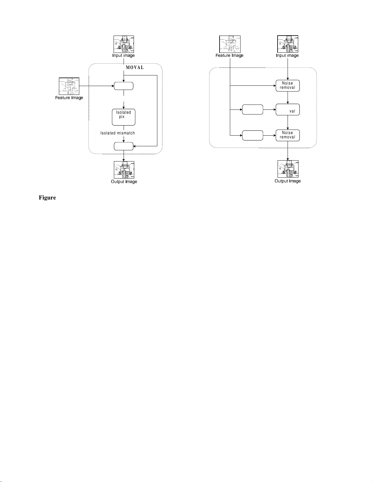
3. FEATURE-BASED FILTERING
In the second stage, the original image is processed by
a feature-based filter for removing noise near the borders of
the extracted line elements. This improves the image quality
and results in more compressible raster image. The filtering
is based on a simple noise removal procedure, as shown in
Figure 3. Mismatch image is constructed from the
differences between the original and the feature image.
Isolated mismatch pixels (and pixel groups up to two
pixels) are detected and the corresponding pixels in the
original image are inverted. This removes random noise and
smoothes edges along the detected line segments.
The noise removal procedure is successful if the feature
image is accurate. The vectorizing method, however, does
not always provide exact width of the lines. The noise
removal procedure is therefore iterated three times as
shown in Figure 4. In the first stage the feature image is
applied as such, in the 2nd stage the feature image is
dilated, and in the 3rd stage it is eroded before input into
the noise removal procedure. This compensates most of the
inaccuracies in the width detection. See [9] for the details
of the morphological dilation and erosion.
The stepwise process is demonstrated in Figure 5 for
a small image sample. Most of the noise is detected and
removed in the first phase. However, in some cases there
are too many mismatch pixels grouped together because of
a wrong estimation of the line width and therefore no pixels
can be filtered. Even if these inaccuracies may have visually
2XWSXW ,PDJH
Isolated
pixel
detection
XOR
,QSXW LPDJH
)HDWXUH ,PDJH
XOR
NOISE REMOVAL
Isolated mismatch pixels
Mismatch pixels
2XWSXW ,PDJH
,QSXW LPDJH)HDWXUH ,PDJH
FILTERING
Dilation
Erosion
Noise
removal
Noise
removal
Noise
removal
Figure 3: Block diagram of the noise removal procedure. Figure 4: Block diagram of the three-stage filtering
procedure.
International Conference Graphicon 1998, Moscow, Russia, http://www.graphicon.ru/
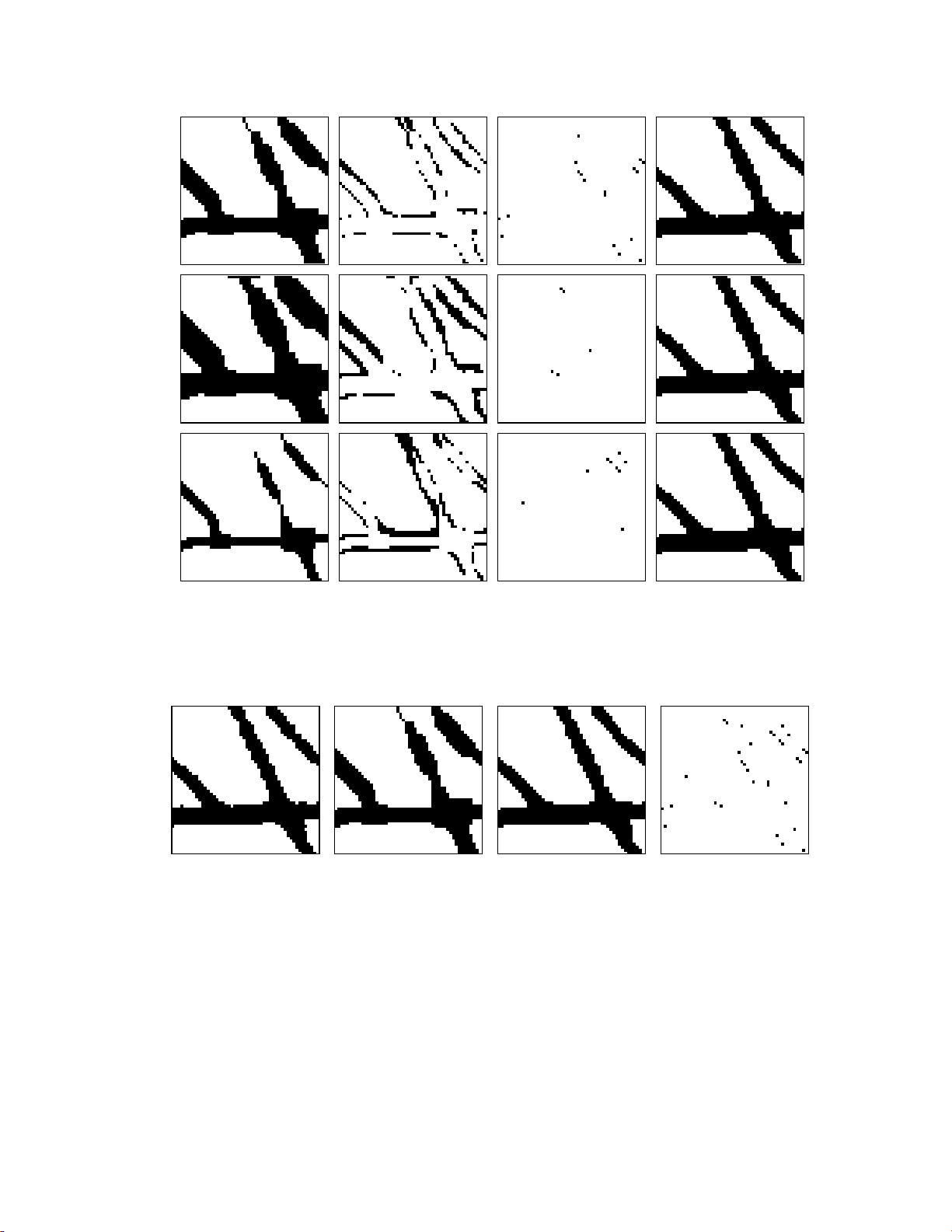
unpleasant appearance in the feature image, they do not
necessarily prevent effective filtering. For example, the
rightmost diagonal line in the feature image is too wide and
the pixels are not filtered in the first two stages. The eroded
version, however, gives a more accurate version of the line
and the noise pixels can be detected and filtered in the 3rd
stage. The result of the entire filtering process is illustrated
in Figure 6.
4. CONTEXT-BASED COMPRESSION
We apply the baseline JBIG as the compression component,
but basically there is no restrictions to use any other
compression method. For example, the progressive mode of
JBIG [2] could also be utilizes. In the baseline JBIG the
pixels are coded by arithmetic coding in scan raster order
using context-based probability model. The combination of
already coded neighboring pixels defines the context. In
each context the probability distribution of the black and
Feature image Mismatch pixels Filtered pixels Filtered image
1
2
3
Figure 5: Illustration of the three-stage filtering procedure. The first line corresponds to the first stage, the second line when
the feature image is dilated, and the last line when the feature image is eroded.
Input image Feature image Output image Filtered pixels
Figure 6: Overall illustration of the feature-dependent filtering process.
International Conference Graphicon 1998, Moscow, Russia, http://www.graphicon.ru/
white pixels are adaptively determined. The current pixel is
then coded by QM-coder [3, 10], the binary arithmetic
coder adopted in JBIG. Statistics start from scratch and they
are updated after the coding of each pixel. The model thus
dynamically adapts to the image statistics during the coding
process. The probability estimation and update are
performed using the state automaton of QM-coder.
5. TEST RESULTS
We compare the proposed method with the existing
compression standards. The following methods are
considered:
• Uncompressed raster file
• Compressed vector file
• ITU Group 3
• ITU Group 4
• Baseline JBIG
• Our method
The compressed vector file represents the result of the
vectorizing when the chain-coded elements are compressed
by ZIP (commonly used universal data compression
method). Baseline JBIG is the basic implementation of the
JBIG binary image compression standard. ITU Group 3 and
Group 4 are the older facsimile standards based on run-
length encoding and two-dimensional READ-code [11, 12].
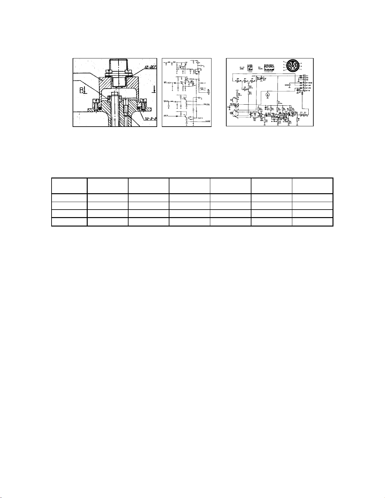
The methods are evaluated by compressing the test images
shown in Figure 7. The compression results are summarized
in Table 1. The vector representation is not space efficient
because it cannot represent small objects efficiently. At the
same time, our method and JBIG can compress the raster
images using less than half of the size required by the
vector file. The corresponding compression ratios (in total)
are 15:1 for the vector file, 32:1 for the JBIG, and 40:1 for
our method.
To sum up, the proposed compression method outperforms
the Group 4 method by 40 % and the baseline JBIG by
20 %. At the same time, the quality of the decompressed
images is visually the same as the original since only
isolated mismatch pixels were reversed. The quality is
sometimes even better because the reversed pixels are
mainly random noise or scanning noise near the line
segments.
6. CONCLUSIONS
A three-stage compression method for compressing bi-level
line-drawing images was proposed. In the first stage, the
raster image is vectorized and a feature image is
reconstructed from the extracted vector elements. In the
second stage, the original image is processed by a feature-
based filtering for removing noise from the original image.
It improves the image quality and therefore results in better
Bolt Module Plus
1765 × 1437
317,590 bytes 1480 × 2053
379,805 bytes 2293 × 1787
512,199 bytes
Figure 7: The set of test images.
Table 1: Summary of the compression results (in bytes).
Original
raster image Compressed
vector file ITU
Group 3 ITU
Group 4 Baseline
JBIG Our
method
Bolt 317,590 28,842 26,409 17,203 12,966 10,210
Module 379,805 12,430 18,979 10,801 7,671 5,798
Plus 512,199 38,837 32,269 21,461 17,609 14,581
TOTAL: 1,209,043 80,109 77,657 49,465 38,246 30,589
International Conference Graphicon 1998, Moscow, Russia, http://www.graphicon.ru/

![Đề thi cuối kỳ môn đồ họa máy tính và lời giải [kèm đáp án chi tiết]](https://cdn.tailieu.vn/images/document/thumbnail/2011/20111224/anlove100/135x160/de_va_giai_3486.jpg)


%20--%3e%3cdefs%3e%3cstyle%3e%20.st0%20{%20fill:%20%23fff;%20}%20.st1%20{%20fill:%20%237800fa;%20}%20%3c/style%3e%3c/defs%3e%3cpath%20class='st1'%20d='M117.78,12.18H43.11c2.9,3.47,4.65,7.94,4.65,12.82,0,5.6-2.3,10.66-6.01,14.29h76.02l7.22-13.56-7.22-13.56Z'/%3e%3cg%3e%3cpath%20class='st0'%20d='M53.58,26.17h-.59v-1.46h.59v-4.96h2.83c1.78,0,2.67.94,2.67,2.82v5.76c0,1.87-.89,2.81-2.67,2.81h-2.83v-4.96ZM55.36,21.37v3.34h1.1v1.46h-1.1v3.34h1.01c.61,0,.91-.37.91-1.1v-5.93c0-.74-.3-1.1-.91-1.1h-1.01Z'/%3e%3cpath%20class='st0'%20d='M65.99,31.14h-1.8l-.31-2.07h-2.19l-.31,2.07h-1.64l1.82-11.39h2.62l1.82,11.39ZM65.28,18.04c-.25.46-.51.77-.75.94-.21.15-.47.22-.79.22-.26,0-.57-.07-.92-.22l-.38-.15c-.14-.05-.26-.07-.37-.07-.3,0-.53.18-.71.54l-.91-.68c.25-.46.51-.77.75-.94.21-.14.48-.21.79-.21.26,0,.57.07.92.21l.38.15c.14.05.26.07.37.07.3,0,.53-.18.71-.54l.91.68ZM61.91,27.52h1.73l-.87-5.76-.87,5.76Z'/%3e%3cpath%20class='st0'%20d='M74.53,26.89v1.52c0,1.91-.89,2.86-2.67,2.86s-2.67-.95-2.67-2.86v-5.93c0-1.91.89-2.86,2.67-2.86s2.67.95,2.67,2.86v1.11h-1.69v-1.22c0-.75-.31-1.12-.93-1.12s-.93.37-.93,1.12v6.15c0,.74.31,1.11.93,1.11s.93-.37.93-1.11v-1.63h1.69Z'/%3e%3cpath%20class='st0'%20d='M81.4,31.14h-1.8l-.31-2.07h-2.19l-.31,2.07h-1.64l1.82-11.39h2.62l1.82,11.39ZM75.9,19.2l1.52-1.91h1.71l1.51,1.91h-1.61l-.76-.95-.75.95h-1.61ZM77.32,27.52h1.73l-.87-5.76-.87,5.76ZM83.1,15.99l-1.76,1.91h-1.26l1.17-1.91h1.86Z'/%3e%3cpath%20class='st0'%20d='M84.86,19.75c1.78,0,2.67.94,2.67,2.82v1.48c0,1.87-.89,2.81-2.67,2.81h-.85v4.28h-1.79v-11.39h2.64ZM84.01,21.37v3.86h.85c.58,0,.87-.36.87-1.08v-1.71c0-.71-.29-1.07-.87-1.07h-.85Z'/%3e%3cpath%20class='st0'%20d='M93.51,19.75c1.78,0,2.67.94,2.67,2.82v1.48c0,1.87-.89,2.81-2.67,2.81h-.85v4.28h-1.79v-11.39h2.64ZM92.66,21.37v3.86h.85c.58,0,.87-.36.87-1.08v-1.71c0-.71-.29-1.07-.87-1.07h-.85Z'/%3e%3cpath%20class='st0'%20d='M98.8,31.14h-1.79v-11.39h1.79v4.88h2.03v-4.88h1.83v11.39h-1.83v-4.88h-2.03v4.88Z'/%3e%3cpath%20class='st0'%20d='M105.36,24.55h2.46v1.62h-2.46v3.34h3.09v1.63h-4.88v-11.39h4.88v1.63h-3.09v3.18ZM108.17,17.29l-1.76,1.91h-1.26l1.17-1.91h1.86Z'/%3e%3cpath%20class='st0'%20d='M112.2,19.75c1.78,0,2.67.94,2.67,2.82v1.48c0,1.87-.89,2.81-2.67,2.81h-.85v4.28h-1.79v-11.39h2.64ZM111.35,21.37v3.86h.85c.58,0,.87-.36.87-1.08v-1.71c0-.71-.29-1.07-.87-1.07h-.85Z'/%3e%3c/g%3e%3ccircle%20class='st1'%20cx='25'%20cy='25'%20r='20'/%3e%3cpath%20class='st0'%20d='M32.78,19.27c2.92,0,4.43,2.55,5.28,5.33l.71,2.17c.14.38-.33.75-.71.75h-5.61c.19-.33.24-.71.09-1.08l-.75-2.45c-.43-1.32-.99-2.64-1.79-3.77.75-.57,1.65-.94,2.78-.94h0ZM25,18.38c3.25,0,4.9,2.78,5.89,5.89l.76,2.45c.14.42-.33.8-.8.8h-11.69c-.42,0-.94-.38-.8-.8l.75-2.45c.99-3.11,2.64-5.89,5.89-5.89h0ZM25,11.35c1.74,0,3.11,1.37,3.11,3.11s-1.37,3.11-3.11,3.11-3.11-1.41-3.11-3.11,1.41-3.11,3.11-3.11h0ZM17.27,19.27c1.08,0,1.98.38,2.73.94-.8,1.13-1.37,2.45-1.74,3.77l-.8,2.45c-.14.38-.05.75.09,1.08h-5.56c-.42,0-.9-.38-.75-.75l.71-2.17c.9-2.78,2.41-5.33,5.33-5.33h0ZM17.27,12.91c1.51,0,2.78,1.27,2.78,2.83s-1.27,2.83-2.78,2.83-2.83-1.27-2.83-2.83,1.27-2.83,2.83-2.83h0ZM32.78,12.91c1.56,0,2.78,1.27,2.78,2.83s-1.23,2.83-2.78,2.83-2.83-1.27-2.83-2.83,1.27-2.83,2.83-2.83h0ZM27.07,28.56v.09c0,.57-.24,1.08-.61,1.46h0v.05c-.38.33-.9.57-1.46.57s-1.08-.24-1.46-.61h0c-.38-.38-.61-.9-.61-1.46v-.09h1.41v.09c0,.19.05.38.19.47v.05c.09.09.28.19.47.19s.38-.09.47-.19v-.05c.14-.09.24-.28.24-.47t-.05-.09h1.41ZM30.99,28.56v.09c0,1.65-.66,3.16-1.74,4.24-1.08,1.08-2.59,1.79-4.24,1.79s-3.16-.71-4.24-1.79l-.05-.05c-1.04-1.08-1.7-2.55-1.7-4.2v-.09h1.41v.09c0,1.27.47,2.4,1.27,3.25h.05c.85.85,1.98,1.37,3.25,1.37s2.4-.52,3.25-1.37c.85-.8,1.37-1.98,1.37-3.25v-.09h1.37ZM34.99,28.56v.09c0,2.78-1.13,5.28-2.92,7.07-1.79,1.79-4.29,2.92-7.07,2.92s-5.23-1.13-7.07-2.92c-1.79-1.79-2.92-4.29-2.92-7.07v-.09h1.41v.09c0,2.4.94,4.53,2.5,6.08,1.56,1.56,3.72,2.5,6.08,2.5s4.52-.94,6.08-2.5c1.56-1.56,2.5-3.68,2.5-6.08v-.09h1.41Z'/%3e%3c/svg%3e)