
EURASIP Journal on Applied Signal Processing 2003:3, 312–316
c
2003 Hindawi Publishing Corporation
Chebyshev Functions-Based New Designs of Halfband
Low/Highpass Quasi-Equiripple FIR Digital Filters
Ishtiaq Rasool Khan
Department of Information and Media Sciences, The University of Kitakyushu, 1-1 Hibikino, Wakamatsu-ku,
Kitakyushu 808-0135, Japan
Collaboration Center, Kitakyushu Foundation for the Advancement of Industry, Science and Technology,
2-1 Hibikino, Wakamatsu-ku, Kitakyushu 808-0135, Japan
Email: ir khan@hotmail.com
Ryoji Ohba
Division of Applied Physics, Graduate School of Engineering, Hokkaido University, Sapporo 060-8628, Japan
Email: rohba@eng.hokudai.ac.jp
Received 12 April 2002 and in revised form 7 August 2002
Chebyshev functions, which are equiripple in a certain domain, are used to generate equiripple halfband lowpass frequency re-
sponses. Inverse Fourier transformation is then used to obtain explicit formulas for the corresponding impulse responses. The
halfband lowpass FIR digital filters designed in this way are quasi-equiripple, having performances very close to those of true
equiripple filters, and are comparatively much simpler to design.
Keywords and phrases: digital filters, FIR, halfband, equiripple, Chebyshev functions.
1. INTRODUCTION
The simplest way of designing finite impulse response (FIR)
digital filters (DFs) is to truncate the infinite Fourier series
of the desired frequency responses, using a window of finite
length [1]. These windows-based designs provide very simple
formulas for the impulse responses (tap coefficients); how-
ever, truncation of the Fourier series results in large ripples
on the frequency responses, especially close to the transition
edges. This builds up a need for development of new design
procedures of FIR DFs having better frequency responses.
One approach to a better frequency response leads to
maximally flat (MAXFLAT) designs [2,3], which have com-
pletely ripple-free frequency responses. However, a price
is paid in terms of wider transition bands, which limits
the applications of these otherwise excellent filters. Classi-
cal MAXFLAT designs have closed form expressions for the
frequency responses, and inverse Fourier transformation is
needed to find the corresponding impulse responses. Some
recent developments [4,5,6,7]havemadeMAXFLATde-
signs as simple as window-based designs by giving explicit
formulas for the impulse responses.
An entirely different approach to better frequency re-
sponse is to spread the ripple uniformly over the entire fre-
quency band. This ensures the minimum of the maximum
size of ripple for a certain set of design specifications. The Re-
mez exchange algorithm [8]offers a very flexible design pro-
cedure for such equiripple filters, and gives excellent trade-
offbetween the transition width and the ripple size. However,
this procedure is relatively complex as it calculates the filter
coefficients in an iterative manner and each iteration involves
intensive search of extrema over the entire frequency band.
Several other filter design techniques can be found in
literature [9,10,11,12,13,14,15,16] and some of them
allow quasi-equiripple frequency responses [11,12,13,14]
in order to pass up the complexity of true equiripple de-
signs. Such a technique is presented in this paper for half-
band low/highpass DFs which have received much attention
of researchers [3,5,12,14,15,16] due to their numerous ap-
plications, like in sampling rate alteration and signal splitting
and reconstruction [1], and so forth. In this paper, we use
Chebyshev functions to obtain halfband lowpass frequency
responses and then use inverse Fourier transformation to
obtain explicit formulas for the corresponding impulse re-
sponses. The resultant filters obtained in this way are not
truly equiripple but simplicity of their design makes them
quite attractive.
2. HALFBAND LOWPASS FREQUENCY RESPONSES
A Chebyshev function of order N,
f(ω)=cos Ncos−1ω,(1)

Chebyshev Functions-Based New Designs of Halfband Low/Highpass Quasi-Equiripple FIR Digital Filters 313
1
0.5
0
−π0π
Figure 1: A Chebyshev functions-based halfband lowpass fre-
quency response given by (2)forN=4.
is an equiripple function of unit amplitude in the interval
|ω|≤1, and it increases sharply with ωfor |ω|>1. The
function f(ω) always has unit magnitude of opposite signs at
ω=+1 and ω=−1foroddvaluesofN, and of the same sign
for even values of N. For the latter case, f(ω)canbeusedto
generate the frequency response of a halfband lowpass digital
filter, as would be shown later in this section. From this point,
Nis assumed to be even in all the subsequent discussion.
It can be noted that 1 −δf(ω), where δ=0.5/f(π/2),
represents the passband of an equiripple halfband lowpass
filter for |ω|≤π/2. A complete halfband lowpass frequency
response can be written as
H(ω)=
δf(−π−ω),−π≤ω≤−π
2,
1−δf(ω),−π
2≤ω≤π
2,
δf(π−ω),π
2≤ω≤π,
(2)
where
δ=1
2cosNcos−1(π/2)(3)
is the amplitude of the ripple on the frequency response.
A typical halfband lowpass response obtained by (2), for
N=4, is shown in Figure 1.
3. THE IMPULSE RESPONSE
The impulse response of an FIR filter, corresponding to the
frequency response given by (2), can be obtained as
hn=1
2ππ
−πH(ω)ejnωdω
=δ
2π−π/2
−πf(−π−ω)ejnωdω −π/2
−π/2f(ω)ejnωdω
+π
π/2f(π−ω)ejnωdω+1
2ππ/2
−π/2ejnωdω,
(4)
where f(ω) takes only even values of Nand is defined by (1).
Direct evaluation of the integrals in (4) seems impossible
for arbitrary values of N. We evaluated them for a large set of
different values of Nand established the following relations:
f(ω)ejnωdω =cos Ncos−1ωejnωdω
=ejnω
N
k=0
akωN−k,
f(π−ω)ejnωdω =ejnω
N
k=0
ak(ω−π)N−k,
f(−π−ω)ejnωdω =ejnω
N
k=0
ak(ω+π)N−k.
(5)
Defining int[x] as the maximum integer less than or equal to
xand j=√−1, akcan be written as
ak=2N−1jk−1N
n1+k(N−k)!
int[k/2]
i=0
(N−i−1)!
i!n
22i
.(6)
The above expressions for the integrals and akwere estab-
lished by looking at pattern of the results obtained by using
different numerical values of Nin (4). They have been veri-
fied for all even values of Nbelow 30, and therefore we con-
jecture that they are true for all even values of N.
Using and simplifying these integrals in (4), we get
hn=sin[nπ/2]
nπ 1−jNδ
N
k=0π
2N−k
ak1+(−1)N−k.(7)
As Nhas only even values, the second term in (7)becomes
zero for odd values of kand we obtain
hn=sin[nπ/2]
nπ
×
1−Nδ
N
k=0
k=even
(−1)k/2πN−k
(N−k)!
k/2
i=0
(N−i−1)!
i!n
22i−k
.
(8)
The impulse response given by (8) is of infinite length and
must be truncated beyond a finite number of terms to real-
ize an FIR filter. This truncation, due to Gibbs phenomenon
[1], would deform the shape of the ripple and result in
nonequiripple frequency responses. However, it can be noted
from (8) that the magnitude of hnfalls very sharply as n
increases, and the truncated coefficients are relatively very
small in magnitude. Therefore, the resulting frequency re-
sponses obtained from the remaining coefficients are very
close to equiripple, as would be shown later in Section 4.
For an arbitrary even value of N, the number of peaks
on the passband of the frequency response defined by (2)is
N−1. Furthermore, it is known that for an even value of
M, a true equiripple halfband lowpass filter of length 2M+1
(in fact 2M−1, as two external coefficients are zeros) has

314 EURASIP Journal on Applied Signal Processing
M−1 peaks on the passband. To make our design as close
as possible to a true equiripple, we truncate hnin (8)beyond
n=N−1(hn=0forn=Nas well as all other even val-
ues of n). Here, it should be noted that keeping more terms
beyond n=Nwould certainly make the response closer to
equiripple, but at the cost of increased filter length. On the
other hand, increasing the length by using a higher value of
Nin (8) would reduce the overall size of the ripple on the
entire frequency response.
It should be noted that the second term in (8)canbe
written in a more understandable way in terms of matri-
ces, and therefore an impulse response of length 2N−1,
N=even, can be written as
h±n=
0.5,n=0,
(−1)(n−1)/2
nπ 1−(B·C)(n+1)/2,n=odd,0<n<N,
0,n=even,0<n<N,
(9)
where Bis a vector of length N/2 + 1 and is defined by
bk=δN(−1)k−1πN−2k+2
(N−2k+2)! ,1≤k≤N
2+1,(10)
and Cis an (N/2+1×N/2) matrix defined by
ck,l =
k−1
i=0
(N−i−1)!
i!l−1
22(i−k+1)
,
1≤k≤N
2+1,1≤l≤N
2.
(11)
It should be noted that B·Cneed to be calculated only once
in (9). It should be also noted that the calculation of B·C
involves high precision terms and calculations performed at
low precision can lead to erroneous results. The lower in-
dexed terms have relatively smaller magnitudes that decrease
further as Nincreases, and therefore these terms are affected
the most. However, a simple check on B·Callows perform-
ing the calculations at low precision. It is observed that for
any value of N, the value of the elements of B·Cincreases
with the index. If this is not the case, that is, the magnitude
of an element of B·Cis greater than the next element, then
this is the indication that roundofferror has dominated and
that particular element should be set to zero. This can be un-
derstood by the following example.
For N=20, the elements of Bhave small magnitudes,
as low as the order of 10−17, and therefore a precision of at
least 17 decimal points must be used; otherwise, the roundoff
errors in the elements of Bwould accumulate in B·Cand
dominate its smaller valued elements. In this example, the
true value of the first element of B·Cis 0.003; used in (9),
it gives h1=0.3173. With a lower precision, for example,
using 16 decimal points, the first element of B·Ccomes
to be 0.3219; used in (9), it gives h1=0.2158. If we use a
much lower precision, say 7 decimal points, and then apply
the above check, that is, set the first element of B·Cas zero,
(9)givesh1=0.3183.
Halfband highpass DFs can be designed by replacing
(−1)(n−1)/2in (9)by(−1)(n+1)/2.
4. COMPARISON WITH EQUIRIPPLE DESIGNS
It can be noted that if B·C=0, then (9) simply gives
the impulse response of a rectangular-windows-based half-
band lowpass filter which is notorious for large ripple closer
to the band edges. This vector B·Ctries to make the re-
sponse equiripple by spreading the ripple uniformly on the
entire frequency band. Therefore, B·C, multiplied by the
term outside the brackets in (9), can be defined as the im-
pulse response corresponding to the error function (devia-
tion from true equiripple) of a rectangular-windows-based
halfband lowpass filter. It should however be noted that the
presented designs are not truly equiripple due to the Gibbs
phenomenon [1] that arises due to the truncation of the im-
pulse response given by (8).
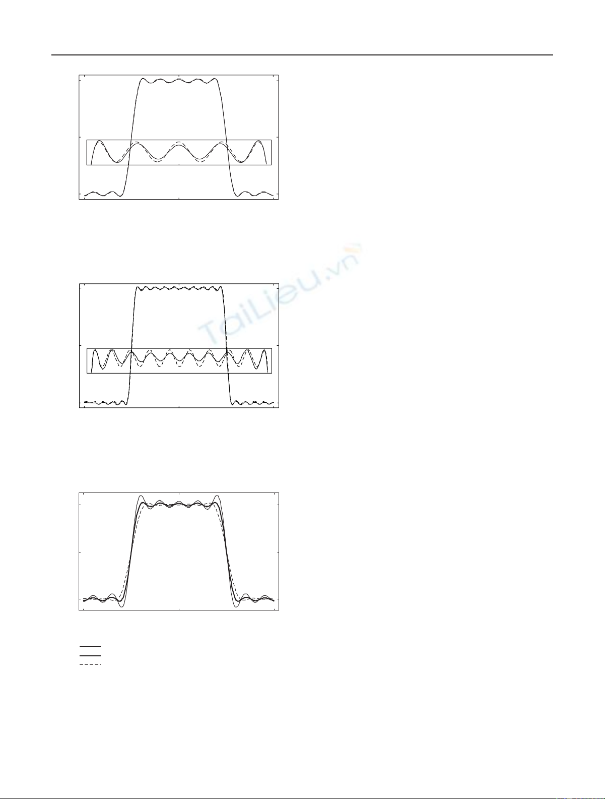
Amplitude responses of halfband lowpass DF designed
using the presented procedure for N=10 and N=20 are
shown in Figures 2and 3, respectively. Clearly, they are very
close to the equiripple responses of the same specifications
obtained by the Remez algorithm, also shown in the figures
for comparison. The smaller windows in the figures show de-
tails of the passbands. It can be noted that the presented fil-
ters have a ripple slightly larger than the Remez algorithm-
based filters near the band edges; however, they appear to be
more accurate in the rest of the bands.
5. A MODIFICATION IN THE DESIGN
It is well known that, in a frequency response, the ripple size
and the transition bandwidth have an inverse relation. Re-
mez exchange algorithm offers high flexibility such that any
desired transition bandwidth can be obtained by suitably ad-
justing the ripple size, and vice versa.
The presented design can be also made little more flex-
ible by multiplying vector B·Cby a nonnegative factor
β. As described earlier, B·Ctends to spread the ripple of
a rectangular-window-based filter over the entire frequency
band. Therefore, a value of β=0 gives the rectangular-
window-based design with shortest transition bandwidth
and large ripple. A value of β=1 gives the presented design,
in which ripple is spread over the entire band at the expense
of relatively wider transition bands. However, as it can be
seen in Figures 2and 3, the designed filters still have ripple of
relatively larger size near the transition edges. From this, we
get the idea that using βslightly greater than 1 would further
reduce the ripple size, and as an obvious consequence, transi-
tion band would be widened. It should however be noted that
if we increase βbeyond a certain value, the actual shape of the
frequency response would start getting deformed. Based on
our experience, we suggest that a value of β>2 should not
be used, and further reduction in the ripple size should be
achieved by increasing the length of the filter.
Chebyshev Functions-Based New Designs of Halfband Low/Highpass Quasi-Equiripple FIR Digital Filters 315
1
0.5
0
−π0π
−1.31 0 1.31
Figure 2: Amplitude responses of halfband lowpass FIR filters de-
signed with the presented procedure (solid line) and the Remez al-
gorithm (dotted line) for N=10. The smaller window shows the
passband details.
1
0.5
0
−π0π
−1.44 0 1.44
Figure 3: Amplitude responses of halfband lowpass FIR filters de-
signed with the presented procedure (solid line) and the Remez al-
gorithm (dotted line) for N=20. The smaller window shows the
passband details.
1
0.5
0
−π0π
β=0
β=1
β=2
Figure 4: Amplitude responses of halfband lowpass FIR filters de-
signed with the modified procedure for N=10 and β=0,1,2. A
value of β=0 gives a rectangular-window-based design, β=1gives
the presented design, and a higher value of βfurther smoothens the
frequency response.
In Figure 4, the magnitude responses of a filter designed
for N=10 and β=0,1,2 are shown.
6. CONCLUSIONS
New designs of Chebyshev functions-based halfband low/
highpass FIR DFs have been presented with explicit formu-
las for the impulse response coefficients. These formulas are
similar to the windows-based formulas with an additional
term that attempts to uniformly spread the ripple over the
entire frequency band, and thus obtains nearly equiripple
frequency responses. Explicit formulas for impulse responses
make the presented designs much simpler as compared to the
available equiripple and quasi-equiripple designs.
ACKNOWLEDGMENTS
The authors wish to thank grant-in-aid for Scientific Re-
search, Ministry of Education, Science, Sports, and Culture
(Kagaku), Japan, and Japan Society for Promotion of Science
(JSPS) for providing financial support for this research.
REFERENCES
[1] P. P. Vaidyanathan, “Design and implementation of digital
FIR filters,” in Handbook of Digital Signal Processing Engineer-
ing Applications, D. F. Elliott, Ed., pp. 55–172, Academic Press,
London, UK, 1987.
[2] O. Herrmann, “On the approximation problem in non-
recursive digital filter design,” IEEE Trans. Circuit Theory, vol.
18, no. 3, pp. 411–413, 1971.
[3] C. Gumacos, “Weighting coefficients for certain maximally
flat non-recursive digital filters,” IEEE Trans. Circuits and Sys-
tems, vol. 25, no. 4, pp. 234–235, 1978.
[4] I. R. Khan and R. Ohba, “New design of full band differentia-
tors based on Taylor series,” IEE Proc. Vision, Image and Signal
Processing, vol. 146, no. 4, pp. 185–189, 1999.
[5] I. R. Khan and R. Ohba, “Efficient design of halfband
low/high pass FIR filters using explicit formulas for tap co-
efficients,” IEICE Trans. Fundamentals, vol. E83-A, no. 11, pp.
2370–2373, 2000.
[6] I. R. Khan and R. Ohba, “Explicit formulas for coefficients
of maximally flat FIR low/high pass digital filters,” Electronics
Letters, vol. 36, no. 23, pp. 1918–1919, 2000.
[7]I.R.KhanandR.Ohba, “Newefficient designs of discrete
and differentiating FIR Hilbert transformers,” IEICE Trans.
Fundamentals, vol. E83-A, no. 12, pp. 2736–2738, 2000.
[8]T.W.ParksandJ.H.McClellan, “Chebyshevapproxima-
tion for non-recursive digital filters with linear phase,” IEEE
Trans. Circuit Theory, vol. 19, no. 2, pp. 189–194, 1972.
[9] A. E. Cetin, O. N. Gerek, and Y. Yardimci, “Equiripple FIR
filter design by the FFT algorithm,” IEEE Signal Processing
Magazine, vol. 14, no. 2, pp. 60–64, 1997.
[10] R. Sakuraba and M. Ikehara, “An analytical design for an
equiripple FIR digital filter by transforming error response,”
Trans. IEICE Japan, vol. J80-A, no. 6, pp. 853–861, 1997.
[11] P. P. Vaidyanathan, “Optimal design of linear phase FIR digi-
tal filters with very flat passbands and equiripple stopbands,”
IEEE Trans. Circuits and Systems, vol. 32, no. 9, pp. 904–917,
1985.
[12] P. Zahradnik, M. Vlcek, and R. Unbehauen, “Almost equirip-
ple FIR half-band filters,” IEEE Trans. Circuits and Systems,
vol. 46, no. 6, pp. 744–748, 1999.

316 EURASIP Journal on Applied Signal Processing
[13] K. Nishikawa, T. Takebe, and A. Kitagawa, “Lowpass FIR dig-
ital filters with flat passband (stopband) and quasi-equiripple
stopband (passband) amplitude characteristics,” Trans. IEICE
Japan, vol. E61, no. 10, pp. 824–825, 1978.
[14] A. N. Willson Jr. and H. J. Orchard, “A design method for
half-band FIR filters,” IEEE Trans. Circuits and Systems-I, vol.
45, no. 1, pp. 95–101, 1999.
[15] P. P. Vaidyanathan and T. Q. Nguyen, “A ‘trick’ for the design
of FIR half-band filters,” IEEE Trans. Circuits and Systems, vol.
34, no. 3, pp. 297–300, 1987.
[16] X. Zhang, K. Intosume, and T. Yoshikawa, “Design of low-
delay FIR half-band filters with arbitrary flatness and its ap-
plication to filter banks,” Electron.Comm.Jpn3, vol. 8, no. 10,
pp. 1–9, 2000.
Ishtiaq Rasool Khan was born in 1969 in
Sialkot, Pakistan. He received his B.S. degree
in electrical engineering from the University
College of Engineering, Taxila, Pakistan in
1992, and his M.S. degree in systems engi-
neering from the Center for Nuclear Stud-
ies (CNS), Islamabad, Pakistan in 1994. He
received his M.S. degree in information en-
gineering and his Ph.D. degree in applied
physics in 1998 and 2000, respectively, from
Hokkaido University, Japan. Dr. Khan worked at Hokkaido Univer-
sity as a Fellow of Japan Society for Promotion of Science (JSPS)
from 2000 to 2002. At present, he is working as the special Re-
searcher at the Foundation for Advancement of Industry and Sci-
ence (FAIS), Kitakyushu, Japan and at the University of Kitakyushu,
Japan. His major research interests include 3D modeling, software
development, and digital signal processing. He is a member of the
Engineering Council, Pakistan, and the Institute of Engineers of
Pakistan.
Ryoji Ohba was born in 1942 in Imaichi,
Japan. He received his M.S. and Ph.D. de-
grees in applied physics in 1967 and 1970,
respectively, from the University of Tokyo,
Japan. He joined Hokkaido University, Sap-
poro, Japan in 1970 and is currently a Pro-
fessor in the Division of Applied Physics,
Graduate School of Engineering, Hokkaido
University. His interests cover instrumenta-
tion, measurement science and technology,
and signal processing. He is the author of Intelligent Sensor Tech-
nology (Wiley). He is a Fellow of the Institute of Physics; and the
Society of Instrumentation and Control Engineers of Japan; and
a member of the Japan Society of Applied Physics; and the Insti-
tute of Electronics, Information, and Communication Engineers of
Japan.


![Báo cáo seminar chuyên ngành Công nghệ hóa học và thực phẩm [Mới nhất]](https://cdn.tailieu.vn/images/document/thumbnail/2025/20250711/hienkelvinzoi@gmail.com/135x160/47051752458701.jpg)


%20--%3e%3cdefs%3e%3cstyle%3e%20.st0%20{%20fill:%20%23fff;%20}%20.st1%20{%20fill:%20%237800fa;%20}%20%3c/style%3e%3c/defs%3e%3cpath%20class='st1'%20d='M117.78,12.18H43.11c2.9,3.47,4.65,7.94,4.65,12.82,0,5.6-2.3,10.66-6.01,14.29h76.02l7.22-13.56-7.22-13.56Z'/%3e%3cg%3e%3cpath%20class='st0'%20d='M53.58,26.17h-.59v-1.46h.59v-4.96h2.83c1.78,0,2.67.94,2.67,2.82v5.76c0,1.87-.89,2.81-2.67,2.81h-2.83v-4.96ZM55.36,21.37v3.34h1.1v1.46h-1.1v3.34h1.01c.61,0,.91-.37.91-1.1v-5.93c0-.74-.3-1.1-.91-1.1h-1.01Z'/%3e%3cpath%20class='st0'%20d='M65.99,31.14h-1.8l-.31-2.07h-2.19l-.31,2.07h-1.64l1.82-11.39h2.62l1.82,11.39ZM65.28,18.04c-.25.46-.51.77-.75.94-.21.15-.47.22-.79.22-.26,0-.57-.07-.92-.22l-.38-.15c-.14-.05-.26-.07-.37-.07-.3,0-.53.18-.71.54l-.91-.68c.25-.46.51-.77.75-.94.21-.14.48-.21.79-.21.26,0,.57.07.92.21l.38.15c.14.05.26.07.37.07.3,0,.53-.18.71-.54l.91.68ZM61.91,27.52h1.73l-.87-5.76-.87,5.76Z'/%3e%3cpath%20class='st0'%20d='M74.53,26.89v1.52c0,1.91-.89,2.86-2.67,2.86s-2.67-.95-2.67-2.86v-5.93c0-1.91.89-2.86,2.67-2.86s2.67.95,2.67,2.86v1.11h-1.69v-1.22c0-.75-.31-1.12-.93-1.12s-.93.37-.93,1.12v6.15c0,.74.31,1.11.93,1.11s.93-.37.93-1.11v-1.63h1.69Z'/%3e%3cpath%20class='st0'%20d='M81.4,31.14h-1.8l-.31-2.07h-2.19l-.31,2.07h-1.64l1.82-11.39h2.62l1.82,11.39ZM75.9,19.2l1.52-1.91h1.71l1.51,1.91h-1.61l-.76-.95-.75.95h-1.61ZM77.32,27.52h1.73l-.87-5.76-.87,5.76ZM83.1,15.99l-1.76,1.91h-1.26l1.17-1.91h1.86Z'/%3e%3cpath%20class='st0'%20d='M84.86,19.75c1.78,0,2.67.94,2.67,2.82v1.48c0,1.87-.89,2.81-2.67,2.81h-.85v4.28h-1.79v-11.39h2.64ZM84.01,21.37v3.86h.85c.58,0,.87-.36.87-1.08v-1.71c0-.71-.29-1.07-.87-1.07h-.85Z'/%3e%3cpath%20class='st0'%20d='M93.51,19.75c1.78,0,2.67.94,2.67,2.82v1.48c0,1.87-.89,2.81-2.67,2.81h-.85v4.28h-1.79v-11.39h2.64ZM92.66,21.37v3.86h.85c.58,0,.87-.36.87-1.08v-1.71c0-.71-.29-1.07-.87-1.07h-.85Z'/%3e%3cpath%20class='st0'%20d='M98.8,31.14h-1.79v-11.39h1.79v4.88h2.03v-4.88h1.83v11.39h-1.83v-4.88h-2.03v4.88Z'/%3e%3cpath%20class='st0'%20d='M105.36,24.55h2.46v1.62h-2.46v3.34h3.09v1.63h-4.88v-11.39h4.88v1.63h-3.09v3.18ZM108.17,17.29l-1.76,1.91h-1.26l1.17-1.91h1.86Z'/%3e%3cpath%20class='st0'%20d='M112.2,19.75c1.78,0,2.67.94,2.67,2.82v1.48c0,1.87-.89,2.81-2.67,2.81h-.85v4.28h-1.79v-11.39h2.64ZM111.35,21.37v3.86h.85c.58,0,.87-.36.87-1.08v-1.71c0-.71-.29-1.07-.87-1.07h-.85Z'/%3e%3c/g%3e%3ccircle%20class='st1'%20cx='25'%20cy='25'%20r='20'/%3e%3cpath%20class='st0'%20d='M32.78,19.27c2.92,0,4.43,2.55,5.28,5.33l.71,2.17c.14.38-.33.75-.71.75h-5.61c.19-.33.24-.71.09-1.08l-.75-2.45c-.43-1.32-.99-2.64-1.79-3.77.75-.57,1.65-.94,2.78-.94h0ZM25,18.38c3.25,0,4.9,2.78,5.89,5.89l.76,2.45c.14.42-.33.8-.8.8h-11.69c-.42,0-.94-.38-.8-.8l.75-2.45c.99-3.11,2.64-5.89,5.89-5.89h0ZM25,11.35c1.74,0,3.11,1.37,3.11,3.11s-1.37,3.11-3.11,3.11-3.11-1.41-3.11-3.11,1.41-3.11,3.11-3.11h0ZM17.27,19.27c1.08,0,1.98.38,2.73.94-.8,1.13-1.37,2.45-1.74,3.77l-.8,2.45c-.14.38-.05.75.09,1.08h-5.56c-.42,0-.9-.38-.75-.75l.71-2.17c.9-2.78,2.41-5.33,5.33-5.33h0ZM17.27,12.91c1.51,0,2.78,1.27,2.78,2.83s-1.27,2.83-2.78,2.83-2.83-1.27-2.83-2.83,1.27-2.83,2.83-2.83h0ZM32.78,12.91c1.56,0,2.78,1.27,2.78,2.83s-1.23,2.83-2.78,2.83-2.83-1.27-2.83-2.83,1.27-2.83,2.83-2.83h0ZM27.07,28.56v.09c0,.57-.24,1.08-.61,1.46h0v.05c-.38.33-.9.57-1.46.57s-1.08-.24-1.46-.61h0c-.38-.38-.61-.9-.61-1.46v-.09h1.41v.09c0,.19.05.38.19.47v.05c.09.09.28.19.47.19s.38-.09.47-.19v-.05c.14-.09.24-.28.24-.47t-.05-.09h1.41ZM30.99,28.56v.09c0,1.65-.66,3.16-1.74,4.24-1.08,1.08-2.59,1.79-4.24,1.79s-3.16-.71-4.24-1.79l-.05-.05c-1.04-1.08-1.7-2.55-1.7-4.2v-.09h1.41v.09c0,1.27.47,2.4,1.27,3.25h.05c.85.85,1.98,1.37,3.25,1.37s2.4-.52,3.25-1.37c.85-.8,1.37-1.98,1.37-3.25v-.09h1.37ZM34.99,28.56v.09c0,2.78-1.13,5.28-2.92,7.07-1.79,1.79-4.29,2.92-7.07,2.92s-5.23-1.13-7.07-2.92c-1.79-1.79-2.92-4.29-2.92-7.07v-.09h1.41v.09c0,2.4.94,4.53,2.5,6.08,1.56,1.56,3.72,2.5,6.08,2.5s4.52-.94,6.08-2.5c1.56-1.56,2.5-3.68,2.5-6.08v-.09h1.41Z'/%3e%3c/svg%3e)