
Hardware Implementation for Entropy Coding and
Byte Stream Packing Engine in H.264/AVC
Ngoc-Mai Nguyen*†, Edith Beigne, Suzanne Lesecq,
and Pascal Vivet
(*)CEA, LETI MINATEC Campus
Grenoble, France
ngoc-mai.nguyen@cea.fr
Duy-Hieu Bui, and Xuan-Tu Tran
(†)VNU University of Engineering and Technology
Hanoi, Vietnam
tutx@vnu.edu.vn
Abstract— Entropy coding and data packing are the major
phases in video coding. The new video coding standard, H.264
Advanced Video Coding (H.264/AVC), has adopted Exp-Golomb
and Context-Adaptive coding methods to increase data
compression ratio. In this paper, we propose hardware
architecture of entropy encoding and byte stream data packing
engines for the H.264/AVC. Our entropy coding engine, that
contains Exp-Golomb and Context-Adaptive Variable Length
Coding (CAVLC), supports baseline and main profile of the
standard. The proposed architecture is implemented using
180nm technology from AMS. The design consumes only 1.56mW
at the operating frequency of 100MHz.
Keywords—H.264/AVC, entropy coding, CAVLC, Exp-Golomb,
Video byte stream
I. INTRODUCTION
Recommended by both the ITU-T Video Coding Experts
Group (VCEG) and the ISO/IEC Moving Picture Experts
Group (MPEG), the H.264 Advanced Video Coding
(H.264/AVC) is the latest, high coding efficiency video coding
standard. An H.264 video encoder contains prediction (intra-
and inter-), transform-quantization and entropy coding phases
as in a regular video encoder. However, it can save
approximately 50% of bit rate in comparison with previous
standards [1] thanks to the adoption of several highlighted
features. The intra-prediction predicts the current block from
encoded pixels in the current frame to remove spatial
redundancies in video data. The H.264/AVC also enables even
neighboring inter-encoded pixels to become reference pixels as
directional spatial prediction for intra-coding [1]. The inter-
prediction estimates the motion of the current block referring to
other frame(s) to remove temporal redundancies in video data.
In H.264/AVC inter-prediction, enhancements such as variable
block size, quarter-sample-accurate motion vector, multiple
reference pictures, improved “skipped” and “direct” motion
inference, weight prediction and de-blocking filter improve
prediction quality and thus coding efficiency [1]. New
transform and quantization were adopted in the H.264/AVC to
process residual data, which is the difference between the
predicted and the current information. Integer-transform on a
smaller block, i.e. 4×4 instead of 8×8, requires only 16-bit
arithmetic computation. It also improves the prediction phase
and enables an exact decoded video quality from all decoders
[1]. In the final phase, i.e. entropy encoding, that removes
statistical redundancies, context-based adapting improves the
coding performance in comparison with previous standards [1].
The H.264/AVC also provides high loss/error robustness
using separated parameter set structures, which keep key
information: NAL (Network Abstraction Layer) unit syntax
structure, FMO (Flexible Macro-block Ordering), ASO
(Arbitrary Slice Ordering), redundant picture, data partitioning
and SP/SI switching pictures enabling decoders to switch data
rate and recover from data losses. For instance, the NAL unit
syntax structure enables “network friendliness” to customize
the use of Video Coded Layer (VCL) for various systems and
networks [1].
Many works propose hardware (HW) implementation of
the standard. However, they mostly focused on the prediction
part of encoders/decoders and on the improvements of
algorithms. In this paper, a full HW implementation of an
Entropy Coding (EC) containing Exp-Golomb and CAVLC
coder for the H.264/AVC baseline profile is proposed. We also
describe briefly the specifications of EC and the H.264/AVC
byte-stream video data and proposed hardware byte-stream
packing engine. The whole design is integrated in an H.264
video encoding system targeting CIF video format. The
synthesis results with a CMOS 180nm technology from AMS
show that our design can work at the frequency of 100MHz to
support 720HD video format. The power consumption result is
the best in comparison with previous ones, only 1.56mW.
The rest of the paper is organized as follows. Section II
briefly introduces the specifications of the entropy coding in
the H.264 and summarizes related works. Section III presents
the entropy coding and the byte stream packing engine is also
proposed in this section. The implementation results are
discussed in Section IV. Finally, Section V highlights the main
contributions and provides future work directions.
II. SPECIFICATIONS AND STATE-OF-THE-ART OVERVIEW
A. Specifications
The output encoded video data is specified by ITU-T
Recommendations [2]. This section will introduce the
specifications of encoded video data and entropy coding.
1) Byte stream encoded video
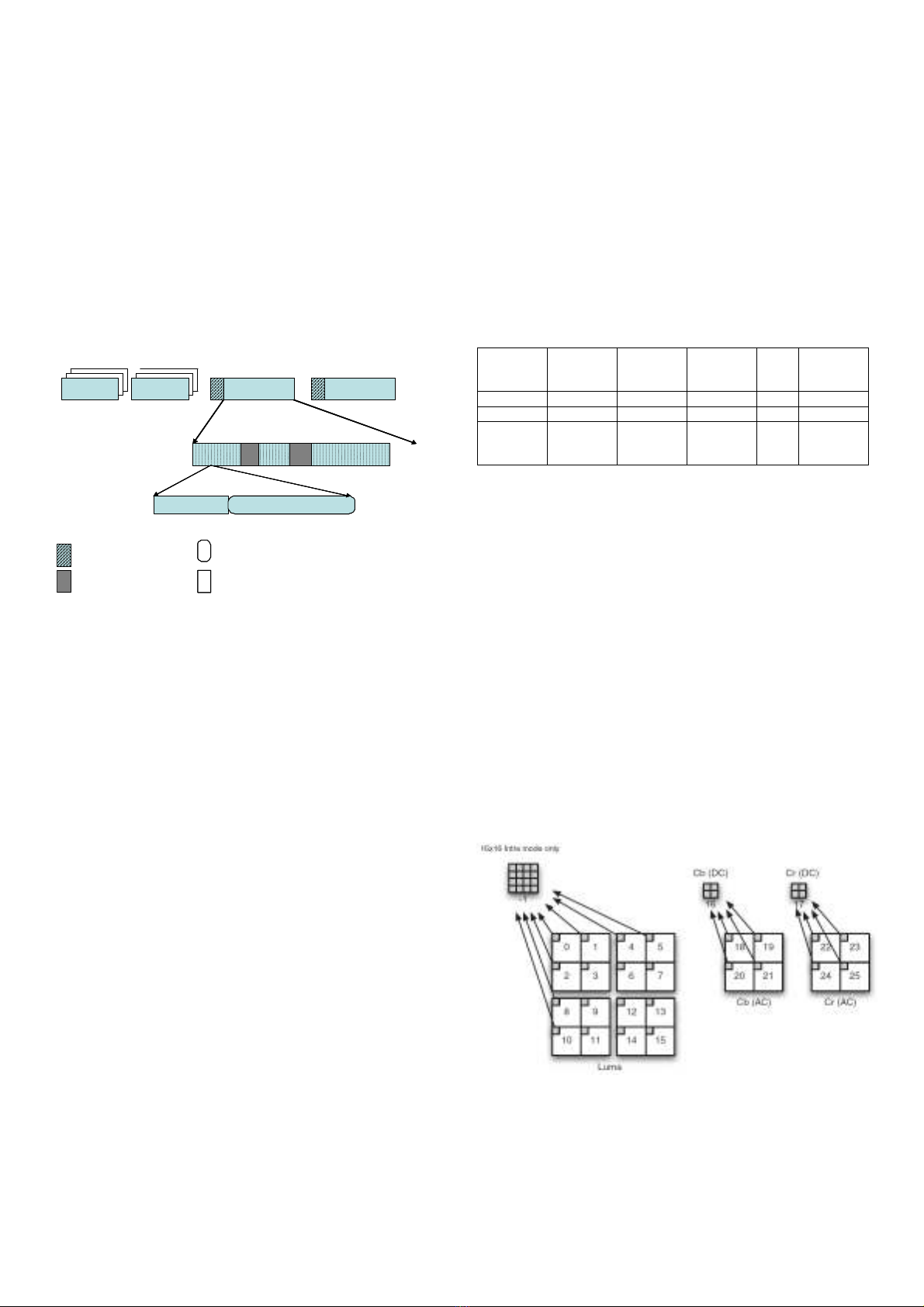
Fig. 1 shows the structure of an encoded video stream.
Video data at Video Coding Layer (VCL) consists of slices.
The first slices of a video sequence are always Instantaneous
Decoder Refresh (IDR) slices forming an IDR frame. Other
IDR slices in the stream start new video sequences. Each slice
is composed of Slice Header (SH) and slice data. SH contains
the information that supports the slice decoding process. Slice
data is a sequence of interchange macroblocks (MBs) and MBs
skipped indication. Each MB contains an MB header and
residual data. The MB header gathers the prediction
information from Intra Prediction (Intra-) and Inter prediction
(Inter-) and other information like Quantization Parameter
(QP) and Coded Block Pattern (CBP). Residual data are
residual post-quantization coefficients.
Fig. 1. Encoded video structure.
Being encapsulated at Network Abstraction Layer (NAL),
the video output data consists of NAL Units (NALUs). Each
VCL NALU contains one slice. Non-VCL NALUs are
Sequence Parameter Set (SPS), Picture Parameter Set (PPS),
End Of Sequence (EOSeq), End Of Stream (EOS), and so on.
SPS is a set of parameters to decode one video sequence. PPS
gathers the parameters for pictures. At least, there are one SPS
and one PPS at the beginning of video stream. EOSeq, EOS,
and many other non-VCL NALUs are optional.
Each NALU starts with one special byte followed by Raw
Byte Sequence Payloads (RBSP) bytes [2].
• The first byte is composed of one forbidden_zero_bit, two
bits representing nal_ref_idc and five bits representing
nal_unit_type. If the NALU is referred by other NALUs,
e.g. NALUs containing SPSs, PPSs, slices of reference
frames, nal_ref_idc is not equal to zero. Otherwise,
nal_ref_idc’s value will be zero. Values of nal_unit_type
are specified in the ITU-T Recommendation.
• Inside RBSP bytes, a byte named
emulation_prevention_three_byte valued 0x03 might be
inserted to prevent the decoder from detecting a start code
inside the content of NALU. Each three bytes having
values in range from 0x000000 to 0x000003 will be
represented as four bytes from 0x00000300 to 0x00000303.
• If the NALU content is already byte-aligned, the final byte
after the content will be 0x80 which contains one bit ‘1’
called rbsp_stop_one_bit and seven bits ‘0’ called
rbsp_alignment_zero_bit. However, normally, the NALU
content is not byte-aligned. The final byte, in this case,
contains firstly the remaining bits of the content, then the
rbsp_stop_one_bit, then the rbsp_alignment_zero_bit(s) if
required.
Byte stream NAL (BSNAL) syntax is specified in the
Annex B of ITU-T Recommendation [2]. A BSNAL unit may
contain the elements as listed in TABLE I. A BSNALU always
starts with a start_code_prefix followed by a NALU.
TABLE I. SYNTAX FOR A BYTE STREAM NAL UNIT
Element Leading
zero
8bits
Zero
byte
Start
code
prefix
NAL
U
Trailing
zero
8bits
Value 0x00 0x00 0x000001 … 0x00
Quantity 0 or more 1 1 1 0 or more
Condition Only the
first
NALU
SPS, PPS,
first slice
of frame
All All Except the
last NALU
In main profile, Exponential Golomb (Exp-Golomb) coding
can be used with Context-based Adaptive Variable Length
Coding (CAVLC) or with Context-based Adaptive Binary
Arithmetic Coding (CABAC). Because of the project’s scope,
we implemented only Exp-Golomb coding and CAVLC in our
main profile entropy coding. As shown in Fig. 1, residual data
is encoded by using CAVLC and the other data by Exp-
Golomb or Fixed-Length Code (FLC). The two entropy coding
techniques will be introduced in the two next sub-sections.
2) Zigzag - CAVLC
Because the TQ engine processes data in blocks of 4×4 or
2×2 coefficients, data entering CAVLC is also in blocks. After
transformation of a block, the DC coefficient is the one having
the lowest frequency, the other coefficients called AC ones.
Input data of each MB contains post-quantization DC
luminance (lumaDC, only in Intra_16×16 mode), lumaAC, DC
chrominance (chromaDC) and chromaAC coefficients. The
order of blocks entering CAVLC in MB is the order of residual
syntax [3], as illustrated in Fig. 2.
Fig. 2. Block scanning order in a MB [3].
SPS PPS SLICE 0 SLICE 1 …
MBs MBs MBs …
MB header Residual data
Slice header
MBs skipped indication
Encoded by CAVLC
Encoded by Exp-Golomb or Fixed-length code
SPS PPS SLICE 0 SLICE 1 …
MBs MBs MBs …
MB header Residual data
Slice header
MBs skipped indication
Encoded by CAVLC
Encoded by Exp-Golomb or Fixed-length code

Coefficients of a block are firstly rearranged in zigzag
order. CAVLC scans the re-ordered coefficients sequence of a
block to find five syntax elements:
• Coefficient token (coeff_token) represents a pair of values,
the total number of non-zero coefficients and the number of
trailing one(s) in the block. Trailing ones are non-zero
coefficients whose values are +/- 1 in the end of the zigzag
sequence. Each block has at most three trailing ones.
• Signs of trailing ones (T1s) are from zero to three bits wide.
They represent the signs of trailing-one coefficients in the
reverse order.
• Levels are values of each non-zero coefficients in the
block, except the trailing one cases. They are also in the
reverse order.
• TotalZeros is the total number of zero coefficients before
the last non-zero coefficient in the zigzag sequence.
• Runs of zeros (run_before) are numbers of zero
coefficients standing before each non-zero coefficients in
the zigzag sequence. Run_before represents the runs of
zeros in the inverse order.
Each syntax element above is encoded using several
different coding tables. The table selection is performed based
on the previous encoded information. This gives the “context-
based adaptive” feature of CAVLC coding technique. For
example, there are five different coding tables to encode
coeff_token. The table selection for coeff_token depends on
number of non-zero coefficients in the upper and left blocks of
the current block. It requires in total 41 different coding tables
in CAVLC encoder.
3) Exp-Golomb encoder
The Exp-Golomb coding principal is to encode each
unsigned code number (codeNum) to produce bit string [2] as
explained below.
The codeNum is represented by the following expression:
codeNum = 2 M + N – 1, where M, N ≥ 0 and 2M > N.
The encoded bit string is then constructed from “prefix”
bits and “suffix” bits. “Prefix” is a series of M zero bits
followed by one bit one. The “suffix” is also M bits long whose
value is equal to N. TABLE II. gives some examples of the
code construction principal.
TABLE II. EXP-GOLOMB CODING EXAMPLES
codeNum Expression Bit string
0 20 + 0 – 1 1
1 21 + 0 – 1 010
2 21 + 1 – 1 011
3 22 + 0 – 1 00100
4 22 + 1 – 1 00101
… … …
Hence, this coding technique is efficient when low-value
codeNums occur more frequently than high-value ones.
In the H.264, Exp-Golomb coding is used alternately with
FLC to represent syntax elements in every NALU. It processes
syntax elements in particular. Based on the statistical
characteristic, each element is represented by a codeNum in
different ways.
• If a syntax element is always larger than or equal to zero
and the more frequently occurred values are the lower
values, the process applied is called Unsigned Exp-Golomb
coding (ue). Value of corresponding codeNum is the same
value of the unsigned element.
• If a syntax element is signed and the expectation value is
zero, the process applied is called Signed Exp-Golomb
coding (se). Value of corresponding codeNum is mapped to
syntax element value k as following:
o codeNum = 2|k| when (k ≤ 0) and
o codeNum = 2|k| - 1 when (k > 0).
• If an unsigned element has different statistical characteristic
from ue, its corresponding codeNum is then mapped to its
value in a special way as indicated in the standard. The
process applied is called Mapped Exp-Golomb coding
(me).
• If an unsigned element has the largest possible value is 1,
then Truncated Exp-Golomb (te) process is applied: the bit
representing syntax element is inversed value of the
element.
B. State-of-Art Overview
In the literature, several hardware entropy coding (EC) and
data packing modules for H.264 video encoding have been
proposed. Here, only the EC in baseline profile (i.e. the Exp-
Golomb and CAVLC coding techniques) is discussed for
comparison purpose.
Actually, the EC is used in the syntax structure of the SPS,
PPS at NAL layer. However, many hardware EC engines only
encode the data at MB level, i.e. the MB header and residual
[4][5][6]. A coding process for SPS, PPS and Slice header has
been implemented in software in [4]. [5] encoded the slice
header in software while the data in SPS and PPS is not
mentioned. Meanwhile, [7] implemented all the EC to encode
SPS, PPS, Slice header and MB in hardware. Hence, [4][7]
proposed full-EC engines with data packer at NAL layer while
other works just present a simple data packer to produce video
data at VCL layer [5] or at a lower one [6].
Many methods, mostly focusing on the CAVLC encoder,
have been introduced to enhance some features of the EC. For
instance, pipelining architectures are usually used for the
CAVLC [8] or for the entire EC [4] to increase the throughput.
The coefficients entering the CAVLC encoder can be pre-
flagged. Actually, the processing time is reduced when the
encoder already knows the characteristic of the data block. In
[4] and [5], some flags indicate the zero coefficients. In [6], the
flags are used not only for zero coefficients but also for the
signs of the non-zero ones. W.J. Lu et al. [7] also tried to
increase throughput in the data packer while avoiding stall state
when the emulation_prevention_three_byte is added into the
data stream. However, the stall state occurs very rarely [4]. As
a consequence, this improvement does not gain much.
To reduce area cost, [6] and [7] tried to reduce the memory
size. Actually, registers block can be implemented instead of
RAM [6] to store reference information of neighboring blocks.
The regularity calculation method decreases the number of
registers in use. Based on the fact that the zero bit sequence
starting codeword is much longer than representation of its
length information, an optimized table to encode coeff_token
is proposed in [7]. In both designs, the level coding process is
realized with calculating circuits instead of a Look-Up Table
(LUT). This latest solution reduces as well the area cost.
Power consumption reduction is another concern. C.Y. Tsai
et al. [5] proposed a low-power EC design that achieves about
69% of power saving in comparison with [4]. The main
features introduced are Side Information Aided (SIA) and
Symbol Look Ahead (SLA) modules to minimize the residual
SRAM access. The SIA module is composed of non-zero and
abs-one flag registers. Each register is a 2-D array of 16×16
flags. Using these two flag registers, the CAVLC encoder can
generate quickly the syntax elements to be encoded. With the
flags in SIA, the SLA module calculates the address of non-
zero coefficients to be read. Hence, accessing all coefficients,
as usual methods do, is not necessary. The design shows
promising power result with 3.7mW at 27MHz and 1.8V for
CIF video. However, with two additional modules, the total
gate count is higher, that is 26.6Kgates in comparison with
23.6Kgates in [4] or 15.86Kgates in [6]. W.J. Lu et al. [7] also
proposed methods to reduce the power consumption. Firstly,
the encoding process for SPS, PPS and slice header in HW
excludes an additional processor to encode this data in
software. This reduces the power consumption and the HW
area of the whole chip. Secondly, since Exp-Golomb and
CAVLC are not working in parallel, the clock is turned off for
non-operating modules to consume less energy. However, the
power result is not reported in [7].Note that [6] shows power
figures of only 2.5mW, even better than the one of the power-
oriented design [5]. This good power figure might be the result
of an effort to reduce the memory its access. However, it is
hard to make a fair comparison because the EC in [6] only
encodes the data in MB level, with a simple data packer.
TABLE III. compares the main features of these designs.
Targeting high throughput quality, both designs [4] and [6]
have promising latency. Operating at 100MHz, the latency of
260cycles/MB [6] enables processing 47.5 HD-frames/s, which
is suitable for real-time applications. However, at the low-
power operating frequency of 27MHz, this design can only
encode 12.8HD-frames/s.
Comparing the two low cost designs [6][7], the latest one
seems to be more suitable with 9.5Kgates compared to
15.86Kgates in [6]. With a slight improvement in the design
techniques, the smaller area of [7] can be explained by a
smaller targeted resolution (i.e. QCIF (171×144) while [6]
deals with HD1080 (1920×1080)), requiring smaller related
memory blocks.
The techniques implemented to reduce the power
consumption in [5] lead to a highest area cost (26.6Kgates). On
the other hand, the design in [7], also targeting low-power, has
the smallest area cost, but its latency of 1905cycles/MB in the
worst case is high, and its resolution is also smaller. To give a
small power consumption, [7] would operate at a frequency
lower than 200MHz. 27MHz might be the frequency suitable
for low-power operation [5][6].
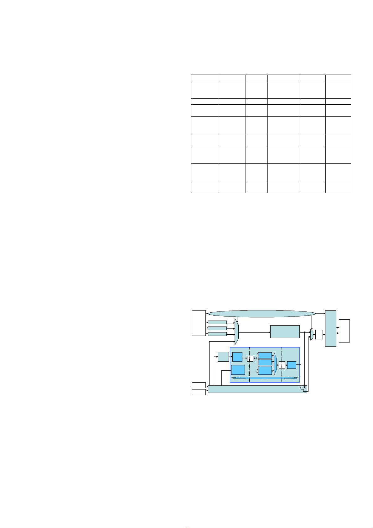
TABLE III. STATE OF THE ART COMPARISON
[4] [5] [6] [7] [8]
Target High
throughput
Low
power
Low cost;
High
throughput
Low cost;
low power
CAVLC &
Exp-
Golomb
Profile Baseline Baseline Baseline Baseline NA
Resolution CIF 30fps to
HD1080
CIF HD1080 QCIF NA
Techno.
(nm)
180 UMC
Artisan
180
TSMC
Artisan
180 TSMC 180 SMIC FPGA
Freq.
(MHz)
100 27 100 200 31.2
Latency
(cycles/MB)
200-500
depends on
QP
NA 260 1905 in the
worst case
NA
Area
(Kgates)
23.6 26.598 15.86 9.504 5731 LUTs
+1562
REGs
Power NA 3.7mW 2.5mW @
(27MHz 1.8V)
NA NA
III. HARDWARE IMPLEMENTATION
A. Overal architecture
Fig. 3 shows the proposed overview architecture of our
entropy coding and data packing engine. Encoded syntax
elements are transferred from entropy coding to data packing
via a FIFO. The main part of entropy coding engine consists of
two encoders, the Exp-Golomb and Fixed-length code (EGF)
and CAVLC modules. SPS, PPS, SH, and MB builders were
implemented to collect the to-be-encoded data and send them
to the EGF module in the specified order. SPS, PPS, SH’s
information is provided by global controller via system
registers. MB header information is received from Intra-, Inter-
and TQ engines.
Fig. 3. Architecture of entropy coder.
Moreover, MB builder also send the residual coefficients
from TQ and related information to zigzag scanner to encode
them by CAVLC module. The data packing engine
concatenates encoded syntax elements into NALUs. The EC
Exp-Golomb &
Fixed-Length Code
CAVLC
EC controller
SPS builder
PPS builder
SH builder
Zigzag
scan
MB builder
NAL
Data
Stream
Packer
FIFO
Global
Control ler
&
register
Prediction
TQ
Statistic
an a lyz e r
Coeff_token
table
selector
LI F O
FIFO Packer
Zero info
encoder
Level
encoder
Coeff-token
&T1s
encoder
CAVLC controller
Memory
access
unit
controller synchronizes the builder and enables data packing
engine to start a new NALU.
Next section will introduce in details the main blocks of the
design.
B. Architecture of main modules
Due to the exponential expression of the codeNum (see
Section II.A), the challenge of implementing Exp-Golomb
encoder in hardware is logarithm operation to calculate M and
then the code length (M = floor (log2(codeNum + 1))). To
solve this problem, some designers implemented coding table
in their Exp-Golomb encoders [4][5]. Another solution was
found and presented in [9] and then applied in several later
designs [6][7][8]. The solution is based on the fact that the
code value is equal to codeNum + 1 and the code word is 2M +
1 bits long, where M is the order of the first one bit in the
binary expression of code value. By this way, output code
words are calculated using combinational circuits.
Our architecture of EGF module (see Fig. 4) also uses the
second solution. The input value is processed up to its type (ue,
se, me or te) in CodeVal calculator sub-block, to calculate code
value. Then, the order of the first ‘1’ bit in code value is
detected in CodeLen calculator sub-block. The code length for
fixed-length code is given by another input port. Code length
and code value are passed through barrel-shifter sub-block to
give out the code output.
Fig. 4. Architecture of Exp-Golomb and Fixed-length coder (EGF).
Zigzag scan module is placed before CAVLC encoder to
re-order the coefficients in blocks from raster scan order into
zigzag order. The three-stage pipelining architecture of
CAVLC module is described in Fig. 3. When zigzag-scanned
coefficients enter the pre-process stage, they are analyzed to
generate five syntax elements of the block. These syntax
elements are then encoded at encoding stage. Finally, the
packing stage receives encoded syntax elements and packs
them into code words of 32-bit length.
We also propose techniques to improve the throughput of
the CAVLC encoder. Using flags to indicate the zero blocks,
zero-skipping technique prevents the zigzag module and the
pre-process stage from scanning all the zero coefficients of a
zero block. This method, thus, saves the time to process zero
blocks that occurs frequently in the post-quantization data.
Moreover, the implementation of table selector for coeff_token
coding inside the CAVLC encoder, instead of in the common
RAM block in H.264 encoder, reduces significantly the
workload of the global controller. This implementation
enhances the global throughput of the H.264 encoding chip but
increases significantly the hardware area of the EC modules.
Moreover, to reduce the area cost for CAVLC encoder, re-
encoded LUT is applied for coeff_token and codeword
calculating is applied for level and run_before syntax
elements. These improving techniques were presented in our
previous work [1][9].
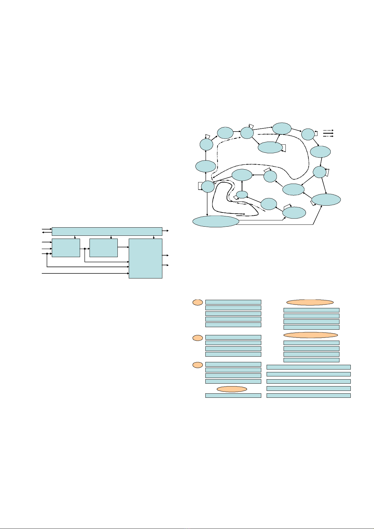
The role of EC controller is to control the builders and
NAL data packing engine to generate a video stream in
NALUs. Our proposed EC controller is implemented as a
Finite State Machine (FSM), see Fig. 5. Before packing and
generating the first video slice, a SPS NALU and then a PPS
NALU are packed. Each video slice starts with a slice header;
the IDR slice starts with IDR slice header due to differences in
syntax. The final video slice of the stream is followed by EoS
NALU.
Fig. 5. Finite state machine to control entropy coder.
According to the specifications, we proposed the syntax of
byte stream NALU as illustrated in Fig. 6. The data packing
engine’s functionalities are to generate the first word with
start_code_prefix; to select the first byte with corresponding
nal_unit_type and nal_ref_idc; to insert the
emulation_prevention_three_byte, if required; and to add
final byte with rbsp_stop_one_bit then one or more
trailing_zero_8bits to 32-bit align the output data.
Fig. 6. Proposed syntax of BSNALU.
Fig. 7 depicts our proposed architecture for NAL data
packing engine. Because the encoded syntax elements from
FIFO can be at any length from 1 to 64 bits, the first step to
packing data is byte aligning the current data and the newly
concatenated element. The byte-aligned data is then checked if
00 00 00 00
00 00 00 01
67 .. .. ..
.. .. .. ..
.. .. .. 00
SPS:
00 00 00 01
68 .. .. ..
.. .. .. ..
.. .. .. 00
PPS:
00 00 00 01
65 .. .. ..
.. .. .. ..
.. .. .. 00
IDR:
00 00 00 01
21 .. .. ..
.. .. .. ..
.. .. .. 00
reference slice, non-IDR
00 00 00 01
01 .. .. ..
.. .. .. ..
.. .. .. 00
non-reference slice, non-IDR
00 00 01 0B
EoStream:
00 00 01 start_code_prefix
00 zero_byte
00 trailing_zero_8bits
00 leading_zero_8bits
XX .. .. NALU
00 00 00 00
00 00 00 01
67 .. .. ..
.. .. .. ..
.. .. .. 00
SPS: 00 00 00 00
00 00 00 01
67 .. .. ..
.. .. .. ..
.. .. .. 00
SPS:
00 00 00 01
68 .. .. ..
.. .. .. ..
.. .. .. 00
PPS: 00 00 00 01
68 .. .. ..
.. .. .. ..
.. .. .. 00
PPS:
00 00 00 01
65 .. .. ..
.. .. .. ..
.. .. .. 00
IDR: 00 00 00 01
65 .. .. ..
.. .. .. ..
.. .. .. 00
IDR:
00 00 00 01
21 .. .. ..
.. .. .. ..
.. .. .. 00
reference slice, non-IDR
00 00 00 01
21 .. .. ..
.. .. .. ..
.. .. .. 00
reference slice, non-IDR
00 00 00 01
01 .. .. ..
.. .. .. ..
.. .. .. 00
non-reference slice, non-IDR
00 00 00 01
01 .. .. ..
.. .. .. ..
.. .. .. 00
non-reference slice, non-IDR
00 00 01 0B
EoStream:
00 00 01 0B
EoStream:
00 00 01 start_code_prefix
00 zero_byte
00 trailing_zero_8bits
00 leading_zero_8bits
XX .. .. NALU
00 00 01 start_code_prefix
00 zero_byte
00 trailing_zero_8bits
00 leading_zero_8bits
XX .. .. NALU
idle
wait_sps_avai
start_isps
isps
start_ipps
ipps
idr_sh
start_idr_sh
sh
start_sh
wait_idr_sh_avai
wait_sh_avai
cycle_for_rst_slheader
start_mbs
mbs
start_eos
eos_end
eos
First slice
Normal slices
Last slice
idle
wait_sps_avai
start_isps
isps
start_ipps
ipps
idr_sh
start_idr_sh
sh
start_sh
wait_idr_sh_avai
wait_sh_avai
cycle_for_rst_slheader
start_mbs
mbs
start_eos
eos_end
eos
First slice
Normal slices
Last slice
CodeVal
calculator
CodeLen
calculator
Barrel-shifter
controller
enable
ack code
valid
mode (Intra/Inter)
type (ue/se/me/te)
input value
fixed-length-code length
code value
code
length
code output
code length
CodeVal
calculator
CodeLen
calculator
Barrel-shifter
controller
enable
ack code
valid
mode (Intra/Inter)
type (ue/se/me/te)
input value
fixed-length-code length
code value
code
length
code output
code length


![Câu hỏi trắc nghiệm Lập trình C [mới nhất]](https://cdn.tailieu.vn/images/document/thumbnail/2025/20251012/quangle7706@gmail.com/135x160/91191760326106.jpg)