
* Corresponding author. Tel./Fax: +98 26-4569555
E-mail addresses: Akbardoost@khu.ac.ir (J. Akbardoost)
© 2014 Growing Science Ltd. All rights reserved.
doi: 10.5267/j.esm.2014.4.005
Engineering Solid Mechanics 2 (2014) 183-192
Contents lists available at GrowingScience
Engineering Solid Mechanics
homepage: www.GrowingScience.com/esm
Size and crack length effects on fracture toughness of polycrystalline graphite
J. Akbardoost*
Faculty of Engineering, Kharazmi University, Mofatteh Avenue, P.O. Box 15719-14911, Tehran, Iran
A R T I C L E I N F O A B S T R A C T
Article history:
Received January 20, 2014
Received in Revised form
April, 10, 2014
Accepted 25 April 2014
Available online
24 April 2014
In this paper, the effects of specimen size and crack length on the fracture toughness
of polycrystalline graphite are studied. The experimental results reported in the
previous studies showed that the fracture toughness of graphite increase in bigger
specimen. It has been also demonstrated that the fracture toughness of graphite is
nearly identical in specimens with crack length ratio less than 0.7 but decreases for
grater crack length ratios. To justify the size and crack length dependency of fracture
toughness, the modified form of maximum tangential stress (MMTS) criterion, which
makes the use of higher order terms in calculating the stress field around the crack tip
is employed. It is shown that the MMTS criterion can provide good estimates for the
fracture toughness of graphite obtained from specimen with different sizes. It is also
indicated that the MMTS criterion can predict very good the reported experimental
fracture toughness data for samples with the crack length ratios less than 0.7.
© 2014 G
r
owin
g
Science Ltd. All ri
g
hts reserved.
Keywords:
Polycrystalline graphite
Fracture toughness
Size effect
Crack length effect
Higher order terms
Modified maximum tangential
stress criterion
1. Introduction
Since graphite has good thermal stability, low permeability, high corrosion resistance, good
performance in electrical and thermal conductivity and good thermal shock resistance, it is employed
frequently in different engineering components such as sliding current connector, refractory graphite
parts, sealing rings, carbon brushes, graphite electrodes, heating elements, etc. However, graphite is
prone to mechanical or thermal failure, especially when graphite parts contain stress concentrators
such as cracks or notches. In other words, the graphite parts might contain cracks, inherent
discontinuities and flaws, which play the role of stress raiser and make the graphite parts very
susceptible to suddenly fracture. The cracks are often created during the manufacturing or machining
processes, or due to the mechanical or thermal loads applied under service conditions. Therefore, it is
urgently required to study the mechanical failure of cracked graphite components. Researchers and

184
engineers have used frequently a fundamental parameter so-called fracture toughness KIf for
determining the strength of cracked components. Fracture toughness presents the resistance of
materials against crack growth under mode I or opening mode loading. Fracture toughness of graphite
is usually measured from standard laboratory specimens with specific geometry, shape and size
limits. It is expected that the fracture toughness obtained from laboratory specimen of different sizes
and shapes is nearly identical. However, experimental results have shown that the fracture toughness
of graphite is significantly dependent on the size, length of initial crack and geometry of specimen
(Chi, 2013; Li et al., 2013; Sakai & Kurita, 1996; Sakai & Nonoyama, 2005; Yamauchi et al., 2000,
2001; Yoon et al., 2011). For example, Li et al. (2013) showed experimentally that the fracture
toughness of NBG graphite obtained from the single-edge-notch beam samples increases by
increasing the size of specimen. For another example, Yamauchi et al. (2000, 2001) demonstrated
that the fracture toughness of graphite measured from two test configurations including edge-cracked
semi-circular bend (SCB) specimen subjected to three-point loading and cracked Brazilian disk
(CBD) are significantly different. Moreover, Sakai and Nonoyoma ( 2005) showed that the length of
initial crack has the influence on the fracture toughness of graphite when the crack length ratio is
more than 0.7. Thus, in order to use the fracture toughness obtained from the laboratory-size
specimen for predicting the onset of crack growth in real size and geometry graphite parts, the effects
of specimen size, initial crack length and geometry on fracture toughness should be considered.
On the other hand, there are several criteria for investigating the size effects on mode I fracture
toughness of quasi-brittle materials such as rocks, concretes, ceramics, etc. For instance, Bazant's size
effect law (SEL) proposed by Bazant (1984)is a well-known criterion which has been used frequently
for taking into account the specimen size effects on fracture toughness of graphite (Li et al., 2013;
Sakai & Kurita, 1996; Sakai & Nonoyama 2005). However, almost all of the size effect criteria (e.g.
SEL) are not able to consider simultaneously the geometry and crack length effects on the fracture
toughness. The aim of this paper is to investigate the size and crack length effects on the fracture
toughness of graphite simultaneously. For this purpose, test data reported by Sakai and Kurita(1995)
is used. They showed experimentally that the fracture toughness for a type of polycrystalline graphite
(IG-11) depends significantly on the size and crack-length of specimen. In order to justify the size
and crack-length dependence of fracture toughness, a modified form of the maximum tangential
stress (MMTS) criterion is used. This criterion takes into account the influence of the higher order
terms in calculating the stress field around the crack tip in addition to the singular terms. As an
important parameter in the MMTS criterion, the critical distance rc is assumed to be size dependent
and a formula proposed recently by Ayatollahi and Akbardoost ( 2012) is employed for describing the
size dependence of rc. The values of KIf for specimens with different crack lengths are also predicted
using the MMTS criterion based on the constant value of critical distance. It is shown that the MMTS
criterion is able to provide good estimates for the fracture toughness of graphite by taking into
account the effects of specimen size and the length of initial crack.
2. Modified MTS criterion
Based on the classical MTS criterion proposed by Erdogan and Sih (1963), fracture occurs
radially from the crack tip and perpendicular to the direction of the maximum tangential stress θm.
Moreover, the crack will be extended when the tangential stress component σθθ along θm and at a
critical distance rc from the crack tip reaches a critical value σθθc (Erdogan & Sih 1963). The
tangential stress around the crack tip under pure mode I loading can be written from the William's
series expansion (Williams, 1957):
(1)
1
2
cos)1(
2
1
2
cos1
22
,
1
1
2nnnn
rA
n
rn
n
n
n
J. Akbardoost / Engineering Solid Mechanics 2 (2014)
185
where r and θ are the conventional crack tip co-ordinates, n is the order of term in the series
expansion and the constant coefficients An are dependent on the specimen geometry and loading
conditions. These coefficients can be generally written in terms of dimensionless parameters An* as:
(2)
*)2/1(
n
n
Nn AwA
in which
Nis the nominal stress and w is a characteristic dimension like the width of single-edge
notched beam (SENB) specimens. Moreover, the dimensionless coefficients An* depend only on the
configuration parameters like the crack length ratio (a/w) and the loading span to width ratio (S/w).
These parameters are independent of the load and the dimensions of samples. Due to symmetry in
mode I loading, the crack growth takes places along the crack direction, i.e.
m=0. Therefore, the
tangential stress
along the fracture direction is obtained from Eq. (1) by setting
=0:
(3)
...53),( 2/3
53
1
0
rArA
r
A
r
The parameter A1 is related to the mode I stress intensity factor KI as
/√2.The
conventional MTS criterion (Erdogan & Sih, 1963) considers only the first stress term and ignores the
higher order terms. It has been recently demonstrated that the higher order terms of crack tip
asymptotic field are no longer negligible and they should be taken into account to characterize the
tangential stress more accurately (Awaji & Sato, 1978; Ayatollahi & Akbardoost, 2012; Ayatollahi &
Aliha, 2011; Aliha & Ayatollahi, 2009, 2013; Mirsayar et al., 2014; Aliha et al., 2010, 2013). By
taking the first two terms in Eq. (3) into consideration, the maximum tangential stress component at
the critical distance rc can be obtained from:
(4)
cc
c
If
cc
c
c
crA
r
K
rA
r
A
33
13
2
3
where A3c is the critical value of A3 and KIf is the critical stress intensity factor or apparent fracture
toughness which is considered to be dependent on the size and geometry of cracked specimen. By
substituting Eq. (2) into Eq. (4) for n= 1 and n=3, Eq. (4) simplifies to:
(5)
)31(
2*
1
*
3
w
r
A
A
r
Kc
c
If
c
According to previous studies and considering the intrinsic features of graphite (Ayatollahi &
Aliha, 2011; Li et al., 2013; Sakai & Kurita 1996), the critical value of σθθc can be assumed to be the
tensile strength of materials, ft. Thus, the mode I brittle fracture occurs when:
(6)
)31(
2*
1
*
3
w
r
A
A
r
K
fc
c
If
t
In order to use Eq. (6) for predicting the onset of fracture, one should first determine the critical
distance rc. There are several formulations in the literature for calculating the value of rc (Bazant et
al., 1991; Bazant & Planas 1998; Karihaloo, 1999; Schmidt, 1980). Recently, Ayatollahi and
Akbardoost (2012) proposed a modified form of Schmidt’s formula (Schmidt, 1980) for determining
the value of rc. The proposed formula can be written as:
(7)
2
*
1
*
3
2
*
1
*
3
2
6
1222
w
K
A
A
w
K
A
A
ff
r
If
If
tt
c
186
In this formula, KIf is the mode I fracture resistance, A1* and A3* are the dimensionless parameters
for the coefficients of first and third stress terms in pure mode I loading. It has been also shown
(Bazant & Planas, 1998; Karihaloo, 1995) that the value of rc depends on the size of specimen and
increases by increasing the specimen size. Therefore, the size dependent value of rc should be
considered in the proposed method. Here, a simplified formula proposed recently by Ayatollahi and
Akbardoost (2012) is used for describing the size dependency of rc:
(8)
w
B
A
rc
1
where the constant coefficients A and B are calculated by a linear regression on fracture resistance
obtained from mode I tests conducted on specimens of different sizes. For calculating A and B, the
value of rc corresponding to each specimen size is first determined by replacing the fracture
toughness (KIf) obtained from the experiment into Eq. (7). Then a linear regression based on Y=M X
+ Q, in which:
A
Q
w
X
A
B
M
r
Y
c
1
,
1
,,
1
is used (see more details in Ayatollahi and Akbardoost (2012)). By simplifying Eq. (6), the variations
of fracture toughness KIf versus the specimen size can be obtained from:
(9)
)31(
2
*
1
*
3
w
r
A
A
rf
K
c
ct
If
in which the value of rc is determined according to specimen size from Eq. (8). Since the proposed
criterion is a modified form of the MTS criterion, it is named the MMTS criterion. In the next section,
the size dependent values of fracture toughness for a polycrystalline graphite reported by Sakai and
Kurita (1995) will be justified using the MMTS criterion. It will be also shown that the fracture
toughness of graphite obtained from specimens of different crack lengths can be predicted using the
MMTS criterion.
3. Graphite experiments
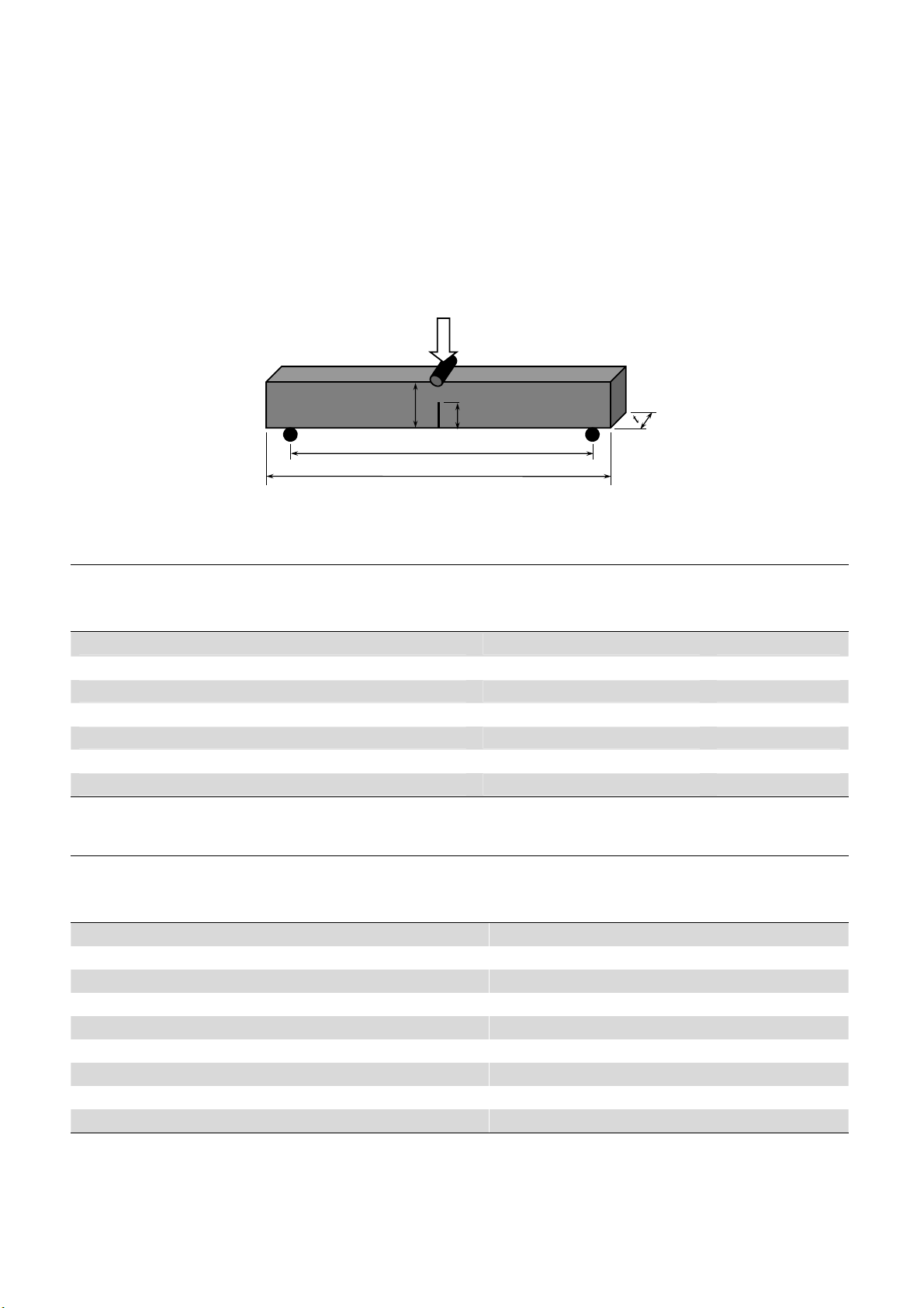
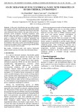
Sakai and Kurita (1995)conducted several experiments on the single-edge notched beam (SENB)
for investigating the dependency of size and crack length on the fracture toughness of graphite. The
schematic of the SENB sample and geometric notations are shown in Fig. 1. The graphite employed
by Sakai and Kurita (1995) was an isotropic polycrystalline graphite (IG- 11) with the following
mechanical properties: bulk density of 1.76 g/cm3,Young's modulus of 9 GPa and tensile strength of
27 MPa. The samples were classified into two categories: 1) the specimen having similar geometry
but different sizes, 2) the specimens with similar characteristic dimension, i.e. w, but different crack
lengths a. In the first category, the widths of specimens were w =2.5, 5, 7.5, 10, 12.5, 17.5, 20 mm
and their crack length ratio was constant and equal to 0.5. The second category was performed on the
specimens with the constant width of 12.5 mm but different crack lengths of a =1.25, 2.5, 3.75, 5,
6.25, 7.5, 8.75, 10, 11.25 mm. For all specimens, the thickness t was 10 mm and the span to width
ratio S/w was equal to 4.The dimensions of samples and loading conditions for the first and second
test categories are listed in Table 1 and Table 2, respectively.
The fracture toughness for the SENB samples is often calculated from:
(10)
*
1
22
2
3Aw
tw
SP
Ku
If
,
J. Akbardoost / Engineering Solid Mechanics 2 (2014)
187
where Pu is fracture load. Sakai and Kurita (1995) did not report the fracture loads of tested
specimens and they only presented the values of fracture toughness as displayed in Table 1 and Table
2. As seen from Table 1, the fracture toughness of graphite depends on the specimen size and
increases by increasing the size of specimen. Meanwhile, the fracture toughness of tested graphite is
nearly constant for specimens larger than w =12.5 mm. Therefore, one can obtained the size-
independent value of KIf by testing the specimen larger than the width of 12.5 mm. Table 2 also
shows that the fracture toughness of graphite is nearly constant for specimens with crack lengths of
a=1.25, 2.5, 3.75, 5, 6.25 and 8.75 mm and decreases for larger crack lengths. It means that the
fracture toughness of graphite depends on the crack length when the crack length ratio is larger than
0.7.
Fig. 1. The schematic of SENB specimen and its dimension notations
Table 1. Graphite specimens and their fracture parameters for size effect analysis
Category I (Size effect analysis) S/w=0.4 , a/w=0.5
rc
(mm)
KIf (MPa.m0.5)
(Sakai and Kurita 1995)
Specimen Dimensions (in mm)
(L×w×t)(Sakai and Kurita 1995)
0.062 0.59 20×2.5×10
0.075 0.62 30×5×10
0.085 0.65 40×7.5×10
0.094 0.68 50×10×10
0.102 0.7 60×12.5×10
0.104 0.705 80×17.5×10
0.106 0.71 90×20×10
Table 2. Graphite specimens and their fracture parameters for crack length effect analysis
Category II (crack length effect analysis) S/w=0.4 , w=12.5 mm
KIf (MPa.m0.5)
(Sakai and Kurita 1995)
Specimen Dimensions (in mm)
(L×a×t)(Sakai and Kurita 1995)
0.7 60×1.25×10
0.68 60×2.5×10
0.73 60×3.75×10
0.72 60×5×10
0.7 60×6.25×10
0.69 60×7.5×10
0.69 60×8.75×10
0.65 60×10×10
0.63 60×11.25×10
S=4w
w
a
P
L


![Bài giảng Vẽ kỹ thuật cơ khí: Chương 2 - Trường ĐH SPKT (ĐH Đà Nẵng) [Mới nhất]](https://cdn.tailieu.vn/images/document/thumbnail/2026/20260303/zinedinezidane06/135x160/64351772685568.jpg)


