ISSN 1859-1531 - THE UNIVERSITY OF DANANG - JOURNAL OF SCIENCE AND TECHNOLOGY, VOL. 22, NO. 11B, 2024 123
STATIC BEHAVIOR OF FGM CYLINDRICAL PANEL WITH POROSITIES IN
HYGRO-THERMAL ENVIRONMENT
Chu Thanh Binh1,2, Nguyen Van Long1,2*, Tran Minh Tu1,2
1Hanoi University of Civil Engineering, Hanoi, Vietnam
2Frontier research group of Mechanics of Advanced Materials and Structures (MAMS)-HUCE, Hanoi, Vietnam
*Corresponding author: longnv@huce.edu.vn
(Received: September 04, 2024; Revised: September 26, 2024; Accepted: October 15, 2024)
DOI: 10.31130/ud-jst.2024.533E
Abstract - In this study, the deflection and stress field of perfect
and imperfect (with and without porosities) functionally graded
(FG) cylindrical panels are determined following the first-order
shear deformation theory (FSDT). The panel rested on the two-
parameter elastic foundation (Pasternak foundation) under
pressure loads and worked in a hygro-thermal environment.
Navier’s solution has been used for simply supported cylindrical
panels to analyze the effects of porosity, geometrical and
foundation parameters, as well as temperature and humidity on
deflection and stress field. The validated examples demonstrate
the reliability of the solution and the self-written Matlab program.
Numerical investigations show a significant hygro-thermal effect
on the static response of the FG panel.
Key words - Cylindrical panel; static analysis; functionally
graded material; porosity; first-order shear deformation theory.
1. Introduction
As a part of advanced materials, functionally graded
materials (FGMs) have attracted the attention of both
domestic and international scientists since their first
appearance in the late 18th century. Due to their superior
mechanical properties, FGMs are the ideal selection for
manufacturing high-performance structures. These
structures had potential applications in adverse
environmental conditions such as fuel combustion
chambers, thermal shields for aircraft, plasma-facing
surfaces in nuclear reactors, and conduits in heat exchange
equipment [1]. Cylindrical panel components are widely
used in aircraft fuselages or nose sections of flying objects
which typically endure high temperatures during operation.
These structures are inhomogeneous, so it is crucial to
study their behavior under normal working conditions [2-
4], while behavior in high-temperature environments [5-7]
poses a significant challenge for scientists.
During the manufacturing process of FGMs,
microscopic voids may appear within the material structure,
especially when using the non-pressure sintering technique
[8]. The presence of these micro-voids significantly reduces
the load-bearing capacity of FGMs with porosities (FGMPo)
[8, 9]. Studies on the mechanical behavior of imperfect FGM
plates (with porosities) and perfect cylindrical panels in
thermal environments have been published by several
authors. However, no publications on the static behavior of
FGM cylindrical panels, taking into account the
hygrotherrmal effects, were found in open sources. This is
an issue that cannot be ignored for structures operating in
environments with high humidity and simultaneously under
high-temperature conditions.
Following the previous results of bending and vibration
analysis of FGMPo panels [10, 11], this study, based on
First-Order Shear Deformation Theory (FSDT), the
deflection and stress fields in FGMPo cylindrical panels
with even and uneven porosity distributions in
hygrothermal environment are determined. The
temperature and moisture fields are assumed to be either
constant or linearly varying across the panel thickness. The
Navier solution is employed to provide explicit from of
displacement and stress fields of simply supported FGMPo
cylindrical panels. After verifying the solution and a
handmade Matlab program as well, the impact of porosity,
temperature, moisture, foundation parameters, and
geometric dimensions on the static behavior of FGMPo
cylindrical panels is evaluated through numerical
investigations.
2. Theoretical Approach
2.1. Porous FGMPo Cylindrical Panel
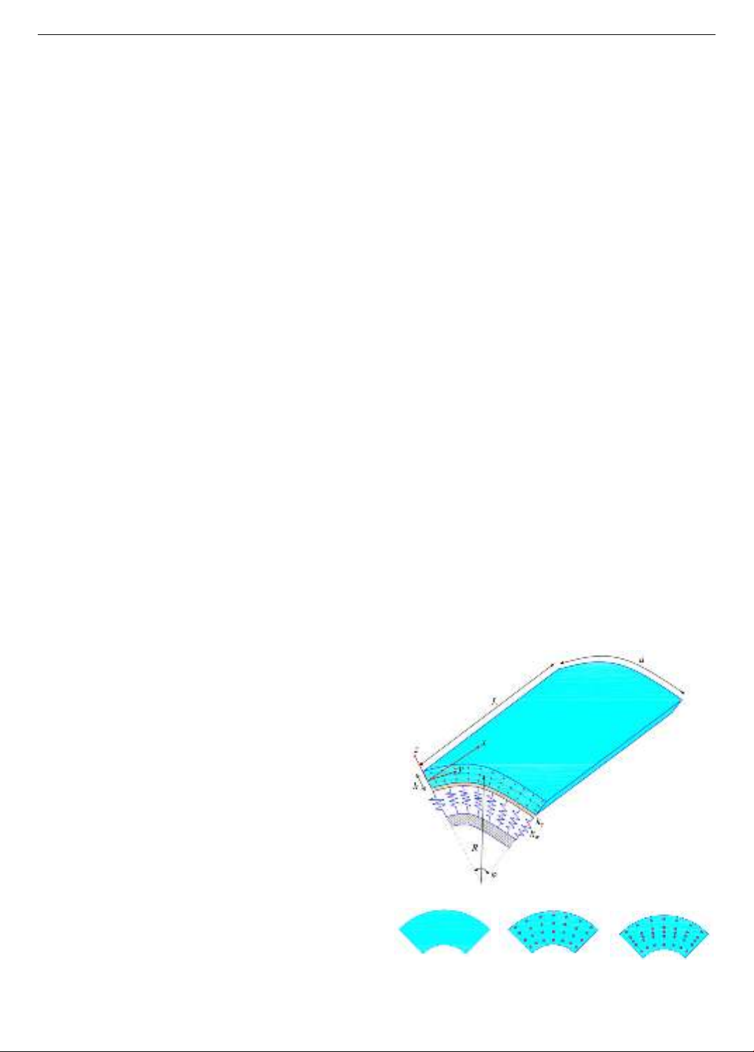
Consider an FGMPo cylindrical panel (Figure 1), with
thickness h, length L, and circumferential length a. The
panel is placed on an elastic foundation with two stiffness
coefficients:
w
k
is the Winkler stiffness coefficient;
s
k
is
the shear stiffness coefficient.
(a): FGMPo cylindrical panel resting on elastic foundation
(b): Perfect FGM
(c): FGPM-1
(d): FGPM-2
Figure 1. FGMPo cylindrical panel on an elastic foundation
and three types of porosity distributions

124 Chu Thanh Binh, Nguyen Van Long, Tran Minh Tu
The FGMPo material consists of two constituent phases:
ceramic and metal; the effective properties
eff
P
are assumed
to vary smoothly according to a power law (P-FGM) along
the panel thickness. The top surface is ceramic-rich, while
the bottom surface is metal-rich.
In terms of the imperfect FGMPo panel, pores develop
along the shell thickness due to manufacturing defects. Two
types of porosity distributions are considered: even porosity
distribution (FGMPo - 1) and uneven porosity distribution
(FGMPo - 2), which are concentrated on the mid-surface of
the shell and decrease linearly to zero at the top and bottom
surfaces. Especially, a perfect FGM material (without
microvoids) can also be obtained. The material properties of
FGMPo include Young’s modulus E, Poisson’s ratio ν,
thermal expansion coefficient α and moisture concentration
expansion coefficient β as follows [12, 13]:
( )
1
( ) ( )
22
p
eff m cm c m
z
P z P P P P z
h
= + + − +
(1)
where:
,
cm c m
P P P=−
p
is the volume fraction exponent
(p ≥ 0);
is the porosity coefficient;
()z
is the function
dependent on the porosity distribution:
( )
0 (FGM)
( ) 1 (FGMPo -1)
1 2 (FGMPo - 2)
z
zh
=
−
/
(2)
2.2. Static Equilibrium Equations
According to FSDT theory, the displacement field of
the cylindrical panel can be expressed as [14]:
( )
( )
( )
( )
( )
0
00
0
,,
,,
,0
x
y
u u x y x y
v v x y z x y z
w w x y
= = + = +
uu
(3)
where:
0 0 0
,,u v w
are the displacements on the mid-surface
along the axis x, y, z;
,
xy
are the rotation angles of the mid-
surface normal around the y - axis and x - axis, respectively.
The strain field can be expressed in the form:
0,
,
0
0, ,
,,
0, 0,
0;
x
x x x
y y y y
xy x y y x
yx
u
w
vz
R
uv
z
= = + +
+
+
=+
0,
0
0,
xz x x
yz y y
w
w
+
= = =
+
(4)
The stress - strain relation is written as follows:
11 12
12 22
66
0
0;
00
xx
yy
xy xy
Q Q T C
Q Q T C
Q
− −
= = − −
(5)
( ) 0
0 ( )
xz xz
yz yz
Gz
Gz
==
where:
11 22 12
22
( ) ( ) ( )
,,
1 ( ) 1 ( )
E z E z z
Q Q Q
zz
= = =
−−
66
()
( ) ;
2 1 ( )
Ez
Q G z z
==
+
00
,,T T T C C C = − = −
00
,TC
are the reference temperature and moisture
concentration, respectively.
The stress resultants of the panel are defined as follows:
( ) ( )
/2
/2
, , 1, ;
h
x x x
y y y
h
xy xy xy
NM
N M z dz
NM
−
==
NM
/2
/2
h
x xz
c
y yz
h
Qk dz
Q
−
==
Q
(6)
where
c
k
is the shear correction factor.
By substituting relation (5) into (6), the stress resultants
can be rewritten in the following form:
0ˆˆ
;
TC
= + − −N A B N N
0ˆˆ
;
TC
= + − −M B D M M
0
s
=QA
(7)
where:
( )
( )
/2 2
/2
, , 1, , ;
h
ij ij ij ij
h
A B D Q z z dz
−
=
/2
/2
( ) ;
h
s
c
h
A k G z dz
−
=
ˆˆ
ˆ ˆ ˆ ˆ
;;
00
TT
T T T T
NM
NM
==
NM
ˆˆ
ˆ ˆ ˆ ˆ
;;
00
CC
C C C C
NM
NM
==
NM
( )
( )
( )
( )
/2
/2
/2
/2
()
ˆˆ
, ( ) 1, ;
1 ( )
()
ˆˆ
, ( ) 1, .
1 ( )
h
TT
h
h
CC
h
Ez
N M z T z dz
z
Ez
N M z C z dz
z
−
−
=
−
=
−
Static equilibrium equations of cylindrical panel resting
on elastic foundation, under transverse load q can be given
in the form [14]:
, , , ,
0; 0;
x x xy y xy x y y
N N N N+ = + =
,, 0;
y
x x y y e
N
Q Q f q
R
+ − − + =
, , , ,
0; 0
x x xy y x xy x y y y
M M Q M M Q+ − = + − =
(8)

ISSN 1859-1531 - THE UNIVERSITY OF DANANG - JOURNAL OF SCIENCE AND TECHNOLOGY, VOL. 22, NO. 11B, 2024 125
The Pasternak’s substrate reaction
e
f
is defined [15, 16]:
2
00e w s
f k w k w
= − +
(9)
Substituting Eq. (7) into (8), equilibrium equations in
terms of the displacement components are obtained as
follows:
( )
( )
12
11 0, 66 0, 12 66 0, 0,
11 , 66 , 12 66 ,
,,
ˆ
ˆ;
xx yy xy x
x xx x yy y xy
TC
xx
A
A u A u A A v w
R
B B B B
NN
+ + + +
+ + + +
=+
( )
( )
22
12 66 0, 22 0, 66 0, 0,
12 66 , 22 , 66 ,
,,
;
xy yy xx y
x xy y yy y xx
TC
yy
A
A A u A v A v w
R
B B B B
NN
+ + + +
+ + + +
=+
( )
( )
12 22 22
0, 0, 0
2
212
0,
22
,
1ˆˆ 0;
x y w
ss
s x x
s T C
yy
A A A
u v k w
RR R
B
A k w A R
B
A q N N
RR
− − − +
+ + + −
+ − + + + =
( )
( )
11 0, 66 0, 12 66 0,
12
0, 11 , 66 ,
12 66 , , ,
ˆ
ˆ
;
xx yy xy
s
x x xx x yy
s T C
y xy x x x
B u B u B B v
BA w D D
R
D D A M M
+ + +
+ − + +
+ + − = +
( )
( )
22
12 66 0, 66 0, 22 0, 0,
12 66 , 66 , 22 ,
,,
ˆˆ
s
xy xx yy y
s
x xy y xx y yy y
TC
yy
B
B B u B v B v A w
R
D D D D A
MM
+ + + + −
+ + + + −
=+
(10)
2.3. Navier solution
For the simply supported (SS) cylindrical panel, the
boundary condition expressions are as follows:
At edge x = 0 and x = L:
00 0;
y x x
v w N M
= = = = =
At edge y = 0 and y = a:
00 0
x y y
u w N M
= = = = =
(11)
Based on Navier’s technique the expansions of
displacements are assumed to be satisfied the SS boundary
conditions:
( ) ( )
( )
( )
0
11
0
11
0
11
, , cos sin ;
, , sin cos ;
sin sin
x mn mn
mn
y mn mn
mn
mn
mn
u U X rx sy
v V Y rx sy
w W rx sy
==
==
==
=
=
=
(12)
where: m, n = 1, 2, 3,....;
, , , ,
mn mn mn mn mn
U V W X Y
are
unknown coefficients;
,.
mn
rs
La
==
The transverse load q and hygro-thermal forces are also
expanded in double-Fourier series as:
11
ˆ
ˆ
ˆ
ˆsin sin
ˆ
ˆ
ˆ
ˆ
mn
T
T
mn
C
C
mn
mn T
T
mn
C
C
mn
q
q
N
N
N rx sy
N
M
M
M
M
==
=
(13)
The transverse load and hygro-thermal force
coefficients are given below:
00
ˆˆ
4
ˆˆsin sin
ˆˆ
ˆˆ
mn
TT
mn La
CC
mn
TT
mn
CC
mn
qq
NN
N rx sydxdy
N
La
MM
MM
=
(14)
Substituting Eqs. (12) - (13) into (10) to get the
following algebraic
,mn
:
ˆˆ
0
ˆˆ
0
00
ˆˆ
0
0ˆˆ
TC
mn mn
mn
TC
mn mn mn
mn mn
TC
mn mn mn
TC
mn mn mn
rN rN
U
V sN sN
KW q
XrM rM
YsM sM
= − −
(15)
where stiffness matrix
K
is symmetric; the remaining
non-zero coefficients include:
22
11 11 66 ;k A r A s
=+
( )
12 12 66 ;k A A rs
=+
12
13 ;
A
kr
R
=−
22
14 11 66 ;k B r B s
=+
( )
15 24 12 66 ;k k B B rs
= = +
22
22 66 22 ;k A r A s=+
22
23 ;
A
ks
R
=−
22
25 66 11 ;k B r B s=+
( )( )
22
22
33 2;
s
ws
A
k k A k r s
R
= + + + +
12
34 ;
sB
k A r
R
=−
22
35 ;
sB
k A s
R
=−
22
44 11 66 ;
s
k D r D s A= + +
( )
45 12 66 ;k D D rs=+
22
55 66 11 .
s
k D r D s A= + +
3. Numerical Studies
Based on proposed Navier solution, a Matlab code is
written to analyze numerical studies with the shear
correction factor as
c
k
= 5/6. FGMPo cylindrical panel
(Al/Al2O3) has the following mechanical properties [17]:
• Al (aluminum):
m
E
= 70 GPa,
m
= 23×10-6 (1/oC),
126 Chu Thanh Binh, Nguyen Van Long, Tran Minh Tu
m
= 0.44,
m
= 0.3.
• Al2O3 (alumina):
c
E
= 380 GPa,
c
= 7×10⁻⁶ (1/oC),
c
= 0.001,
c
= 0.3.
The non-dimensional parameters are defined as
follows [18]:
( )
3
*
0
4
*
3
0
4
4 2 3
00 2
10
( ) , ,
2
( ) , , ,
22
10 , , , ,
2 2 2 2 2
,,
12 1
c
xx
c
xx
w s m
m
mm m
Eh a
w x w x
qa
h L a
zz
qL
Eh L a h L a h
ww qL
qa
k L k L E h
K J D
DD
=
=
= =
= = = −
(16)
There are two cases of studies obtained to confirm the
solution reliability: (i) Verification of the deflection of the
FGM cylindrical panel under mechanical load; (ii)
Verification of the deflection of the FGM plate subjected
to mechanical-thermal-moisture loads.
Table 1 presents non-dimensional deflection
0
1,
22
ab
ww
h
=
of FGMPo cylindrical panel (Al/ZrO2)
under uniform tranverse load: q = 106 Pa, h = 0.01 m,
L = a = 0.2 m. The results are compared to solutions given
by Sander and Zhao et al. [7].
Table 1. Non-dimensional deflection
w
FGMPo cylindrical
panel wih various p
p
Zhao and cs. [7]
Present
Differences (%)
0
0.04267
0.04264
0.07
0.5
0.05425
0.05421
0.07
1
0.06072
0.06067
0.08
2
0.06658
0.06652
0.09
5
0.07235
0.07229
0.08
Table 2. Non-dimensional deflection
ˆ
w
of FGM plate with
various foundation coefficients and geometrical parameter a/h
Sources
a/h = 10
a/h = 20
a/h = 50
00
0, 0KJ==
Zidi et al. [19]
1.79156
0.71642
0.41516
Present
1.79221
0.71637
0.41514
Difference(%)
0.036
0.007
0.005
00
100, 0KJ==
Zidi et al. [19]
1.29862
0.52553
0.30557
Present
1.29951
0.52554
0.30556
Difference(%)
0.069
0.002
0.003
00
100, 100KJ==
Zidi et al. [19]
0.20193
0.08396
0.04920
Present
0.20221
0.08398
0.04920
Difference(%)
0.139
0.024
0.000
Table 2 shows the non-dimensional deflection of
FGMPo square plate (Ti-6Al-4V/ ZrO2) resting on an
elastic foundation subjected to a sinusoidally distributed
mechanical-hygro-thermal loads [19], with a = L, R →∞.
The non-dimensional parameters are defined as follows:
( )
3
2
0
42
42
00
10
ˆ,;
22 12 1
,
c
ws
Eh
D L a
w w D
qL
k L k L
KJ
DD
= =
−
==
(17)
The comparison between maximum non-dimensional
deflection and Navier solution obtained via FSDT with
four displacement variables by Zidi et al. [19].
Table 1 and Table 2 depict the insignificant difference
between this study and the precious research, thus, the
analytical solution and the written Matlab code are reliable.
Unless otherwise stated, the following numerical
studies apply for FGMPo (Al/Al2O3), with input
parameters: material FGMPo - 2, p = 2, ξ = 0.15,
h = 0.01 m, R/h = 100, L = a = 0.1×R, transverse load
q = -5×10⁶ Pa, temperature and moisture increase gradually
ΔT = 50oC, ΔC = 0.5%.
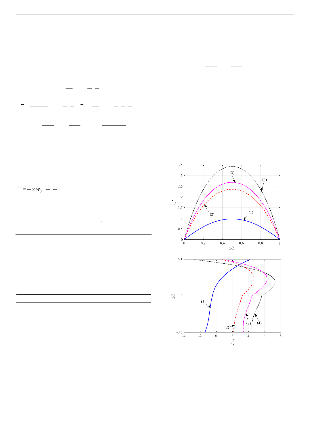
(a) Variation of w* at the cross- section y = a/2
(b) Variation of
*
x
at the center of cylindrical panel
Figure 2. Variation of w* and shear stress
*
x
of cylindrical
panel with various temperature and moisture parameters
Figure 2 shows the influence of temperature and
moisture parameters on the changes in deflection and stress
(w*,
*
x
) of the FGMPo cylindrical panel. The applied load
includes mechanical load and thermal and moisture factors,
varying across four cases: (1) ΔT = 0, ΔC = 0;
ISSN 1859-1531 - THE UNIVERSITY OF DANANG - JOURNAL OF SCIENCE AND TECHNOLOGY, VOL. 22, NO. 11B, 2024 127
(2) ΔT = 50oC, ΔC = 0.5%; (3) ΔT = 100oC, ΔC = 0.5%;
(4) ΔT = 50oC, ΔC = 1%. The graph indicates that thermal-
moisture loading significantly affects the bending behavior
of the cylindrical panel. In particular, the presence of
thermal-moisture factors increases the maximum
deflection
*
max
w
by 2.44, 2.78 and 3.55 in cases (1), (2), (3)
and (4), respectively. Additionally, hygro-thermal factors
have led to the variation pattern of stress, with the positions
of extreme stress points differing from those under purely
mechanical loading. It is necessary to have detailed studies
for each case to consider their effects.
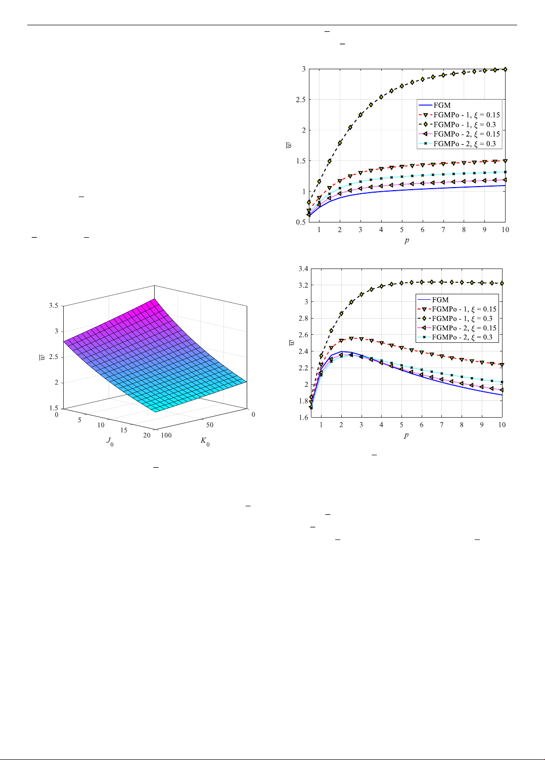
Figure 3 illustrates the impact of the elastic foundation
parameters
00
,KJ
significantly one the dimensionless
deflection
w
of cylindrical panel. Moreover, as the
stiffness of the elastic foundation
00
,KJ
increases (with
higher values of the foundation parameters), the deflection
w
declines:
w
decreases almost linearly with an increase
in
0
K
, and decreases rapidly in a nonlinear manner with
an increase in
0.J
Figure 3. The effect of elastic foundation parameters
00
,KJ
on
dimensionless deflection
w
of cylindrical panel
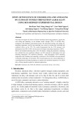
Figure 4 shows the impact of material parameters (the
volume fraction index p, porosity coefficient ξ and porosity
distribution types) on the dimesionless deflection
w
of
cylindrical panel. It can be observed that there is a clear
difference when the panel is subjected only to mechanical
load and when it is subjected to the combination of
mechanical, thermal, and moisture load.
To be more specific that in the case of panel suffering
mechanical load only (as shown in Figure 4a with different
porosity distribution types and porosity coefficient ξ, when
p increases (it means that the amount of ceramic falls) the
deflection of cylindrical panel goes up. The perfect FGM
panel has the smallest deflection, while imperfect FGM
panels show larger deflections; for the same porosity
coefficient ξ, FGPM-2 has a smaller deflection compared to
FGPM-1. For imperfect FGM panels, as the porosity
coefficient ξ increases, the stiffness of the panel decreases,
leading to increased deflection. Besides, for each p, when
ξ ranges from 0.1 to 0.3, the even porosity distribution has a
greater increase than the uneven ones. For instance, at
p = 10, when ξ increases from 0.1 to 0.3 FGMP-2 panel has
deflection
w
grows 10.65%, whereas when FGMP-1 panel
has deflection
w
increases by 99.34%.
(a) ΔT = 0, ΔC = 0
(b) ΔT = 50 oC, ΔC = 0.1%
Figure 4. Variation
w
of cylindrical panel according to
the volume fraction index p, porosity coefficient ξ and porosity
distribution
In the case of panel suffering mechanical, thermal, and
moisture load (as given in Figure 4b): when p changes,
deflection
w
has complicated variation: initially when p is
small,
w
goes up when p has an improvement, when p is
big enough
w
reaches the peak. After that,
w
declines
slightly while p keeps going up. he FGPM-1 distribution
exhibits the highest deflection compared to the perfect
FGM and FGPM-2 (with the same porosity coefficient ξ);
as ξ increases, the deflection of FGPM-1 also increases.
FGPM-2 and the perfect FGM panel exhibit different
behaviors depending on the index p: when p is insignificant
(p ≤ 2.5), the perfect FGM has the largest deflection, and
increasing the porosity coefficient ξ of FGPM-2 reduces
deflection; for large (p ≥ 4.5) the situation reverses, with
the perfect FGM having the smallest deflection, and
increasing the porosity coefficient ξ of FGPM-2 results in
increased deflection.
Figure 5 depicts the variation of the dimensionless
deflection of the cylindrical panel based on the aspect
ratios a/R and R/h. It is observed that increasing the ratios


![Giáo trình Cấu trúc dữ liệu và giải thuật - Trường CĐ Cơ điện Hà Nội [Mới nhất]](https://cdn.tailieu.vn/images/document/thumbnail/2026/20260323/lionelmessi01/135x160/58171774381670.jpg)


![Giáo trình Tiện nâng cao (Nghề Cắt gọt kim loại, Trình độ Cao đẳng) - Trường Cao đẳng Cơ điện Hà Nội [Mới nhất]](https://cdn.tailieu.vn/images/document/thumbnail/2026/20260323/lionelmessi01/135x160/48101774403543.jpg)


