
Chapter 27
Voice Call Continuity
This chapter is devoted to the Voice Call Continuity (VCC) feature in the IMS. VCC, which
is specified in 3GPP TS 23.206 [27] and 24.206 [26], allows smooth transitions of voice calls
executed over the IMS and Circuit-Switched (CS) calls and vice versa. The feature allows a
double IMS/CS terminal to initiate or receive a voice call in either the IMS or CS domain and
move it to the other domain during the duration of the call.
VCC considers voice calls exclusively. At the time of writing, 3GPP is standardizing an
enhanced version of VCC that includes other types of media streams different than audio.
This is known as the Multimedia Session Continuity (MMSC), which it is not considered in
this chapter.
VCC fills an important gap in the transition of CS to IMS. Consider a user that is accessing
the IMS over a narrow bandwidth packet data channel. For example, this narrow bandwidth
channel can be a regular GSM cellular access over GPRS. The GPRS connectivity is used for
signaling and, thus, for SIP signaling towards the IMS. Voice over IP (e.g., RTP packets) will
not have the appropriate quality of service, mostly due to the delays and lack of bandwidth.
However, CS connections are available, and working reasonably well. So, with the VCC
feature enabled, the user can establish audio communications that use a regular CS bearer.
The session is controlled with SIP in the IMS. Assume now that, at a later time, the user
initiates another packet data IP-CAN access with higher bandwidth, perhaps Wireless LAN,
or perhaps cellular High Speed Packet Access. He can then move the CS audio stream over
the packet data IP-CAN, and perhaps enrich the session with video or some other data stream.
The goal of VCC is thus: maintain existing audio calls at any cost when the user moves
between areas with different connectivity characteristics. This is achieved by handing the
audio stream from CS to IMS or vice versa. The feature can be implemented transparently
from the point of view of the user. However, the feature requires VCC-enabled dual-mode
IMS/CS terminals and network support.
Because of the interaction between IMS and CS networks, this chapter assumes that the
reader has basic knowledge of the GSM architecture and its evolution into 3G networks.
27.1 Overview of Voice Call Continuity
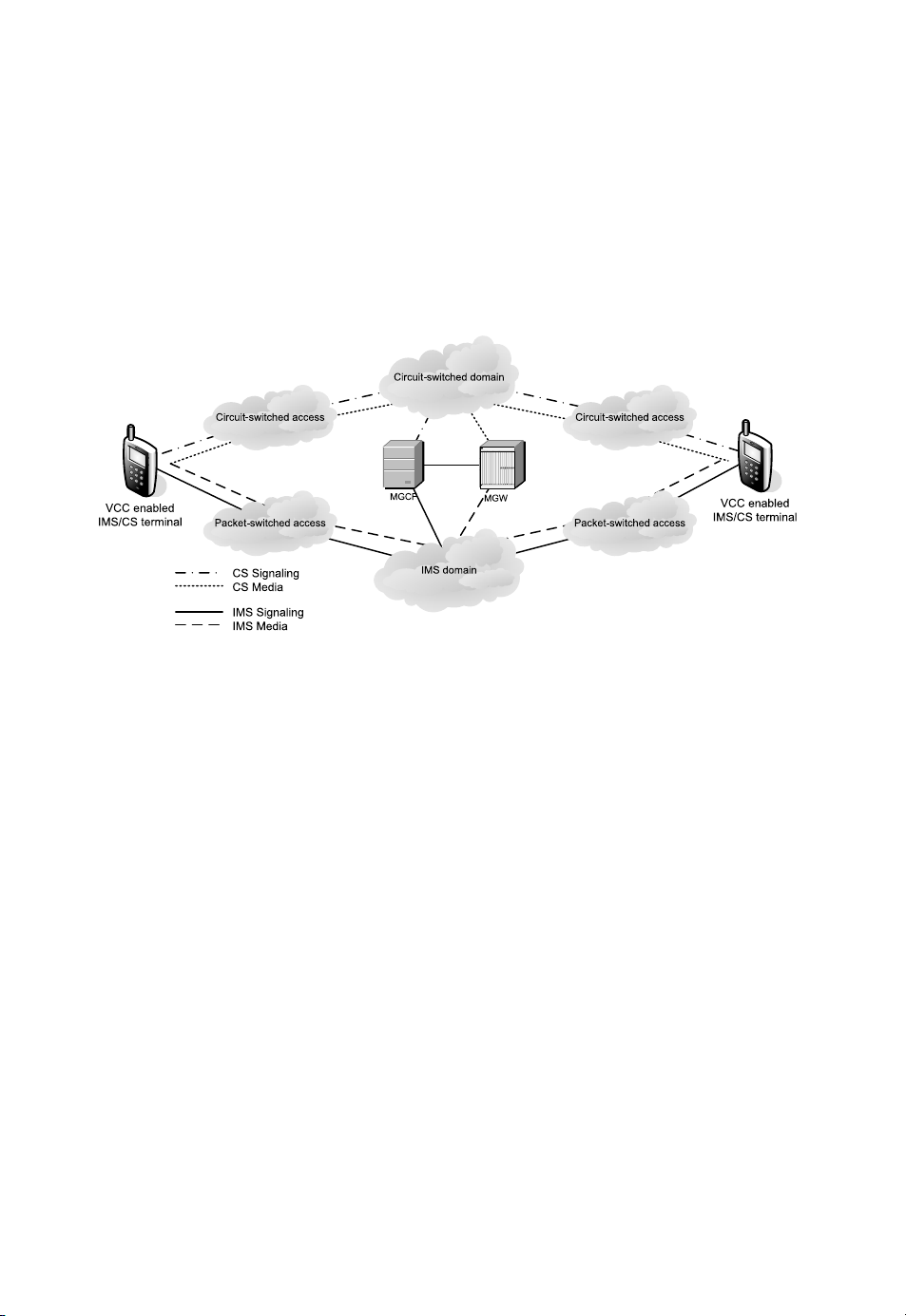
Figure 27.1 presents a high-level overview of the VCC architecture. The figure shows
two VCC-enabled dual-mode IMS/CS terminals. Both can have access to packet-switched
accesses, which leads to an IMS core network, and CS accesses, which leads to the CS core
´ıa- M ar t´ın
The 3G IP Multimedia Subsystem (IMS): Merging the Internet and the Cellular Worlds Third Edition
Gonzalo Camarillo and Miguel A. Garc
© 2008 John Wiley & Sons, Ltd. ISBN: 978- 0- 470- 51662- 1
560
CHAPTER 27. VOICE CALL CONTINUITY
network. A PSTN gateway composed of an MGCF and MGW interfaces the IMS domain
with the CS domain. While Figure 27.1 shows two VCC-enabled terminals, the feature
applies to each terminal in an independent way, so each terminal can use either of the CS
or IMS domains in its own call leg without support from the remote terminal.
VCC is always implemented in the home network of the served user. VCC introduces the
notion of anchoring, which consist of splitting the call into two call legs, and introducing a
fixed point in the network where the two legs are anchored. This allows to hand one leg from
one domain to the other without creating interferences with the remaining leg.
Figure 27.1: Overview of the VCC architecture
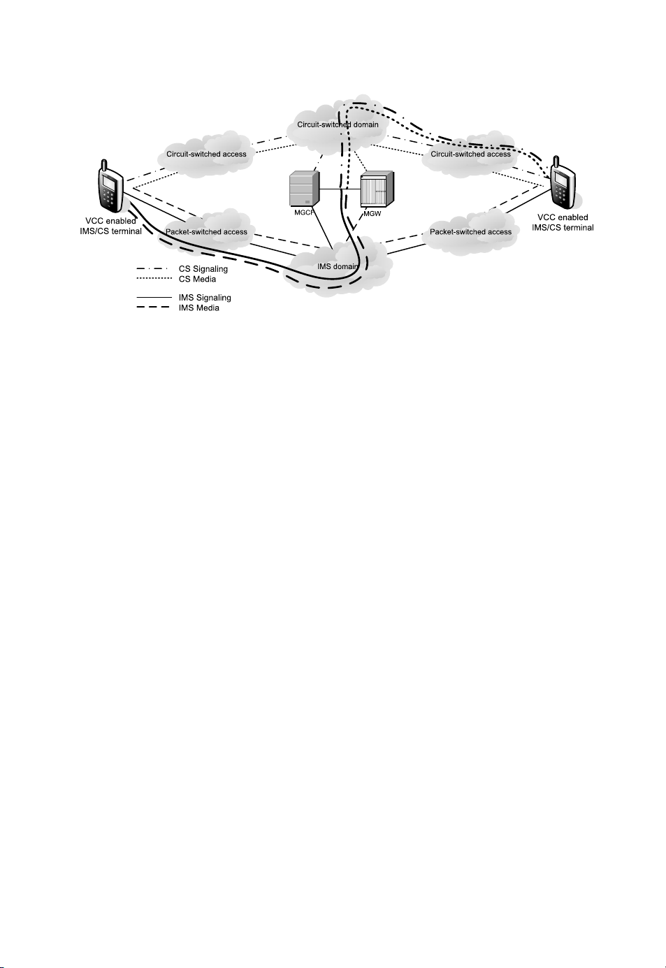
Figure 27.2 shows a possible usage of a call established between two VCC-enabled
terminals. One terminal is using the IMS signaling and media to make the call; the other
is using the CS signaling and media. At any point in time, either of the two terminals can
transfer its own leg to the other domain without disrupting the communication.
Other more complex combinations are also possible. For example, a VCC-enabled
terminal can initiate IMS signaling to establish a call that uses CS media. Then, later, the
terminal can replace the CS audio stream with an RTP audio stream that uses the IMS.
VCC also introduces the notion of routing numbers, which are intermediate telephone
numbers that are used to route the call appropriately via the nodes that provide the
VCC function. The CS Domain Routing Number (CSRN) is a dynamic routing number
that provides routing from the IMS to the CS domain. The IP Multimedia Routing
Number (IMRN) is a routable number that points to the IMS from the CS point of view.
Effectively, the IMRN is a Tel URL that is considered as a Public Service Identity (PSI) in
the IMS.
VCC also introduces the notion of a VCC Domain Transfer Number (VDN), which is
an E.164 number that the terminal can used to request a domain transfer from IMS to the
CS domain. The VDN is not a number that resolves to any of the VCC nodes; it is merely
a regular E.164 number whose semantics is “activate a domain transfer”. There is also a
counterpart VCC Domain Transfer URI (VDI), which is a SIP URI that the UE can use to
perform a domain transfer from the CS domain to the IMS domain. Like the IMRN, the VDI
is also a PSI. The VDI has the semantics of “activate a domain transfer”. The VDI and VDN
are assumed to be pre-provisioned to the terminal.
27.2. VCC ARCHITECTURE
561
Figure 27.2: Example of signaling and media path with VCC-enabled terminals
27.2 VCC Architecture
The VCC feature introduces the concept of a VCC-enabled terminal, which is a terminal
that has access to traditional CS voice and IMS applications. The VCC-enabled terminal
implements domain selection policies for both originating calls and domain transfers. This
policy is used when selecting a domain for originating calls. On the terminating side, it
controls the user preferences for terminating calls. The VCC-enabled terminal stores the
VDN and VDI to be used for domain transfer execution. In addition, a VCC-enabled terminal
implements procedures for transferring a leg from circuit-switched to IMS or vice versa.
The VCC-enabled terminal is configured with an E.164 number, so that it is reachable
from the CS domain, as well as a TEL URL and a SIP URI to be reachable from the IMS
side. Thus, there is a correlation between these numbers in different domains.
VCC also introduces the concepts of the VCC application, which is a collection of
functional entities that provide all of the required functionality for selecting the domain (CS
or IMS) for terminating calls and to assist the VCC-enabled phone for transferring a leg from
one domain to the other. The VCC application also provides the anchoring point to enabling
transfer of domains during active calls.
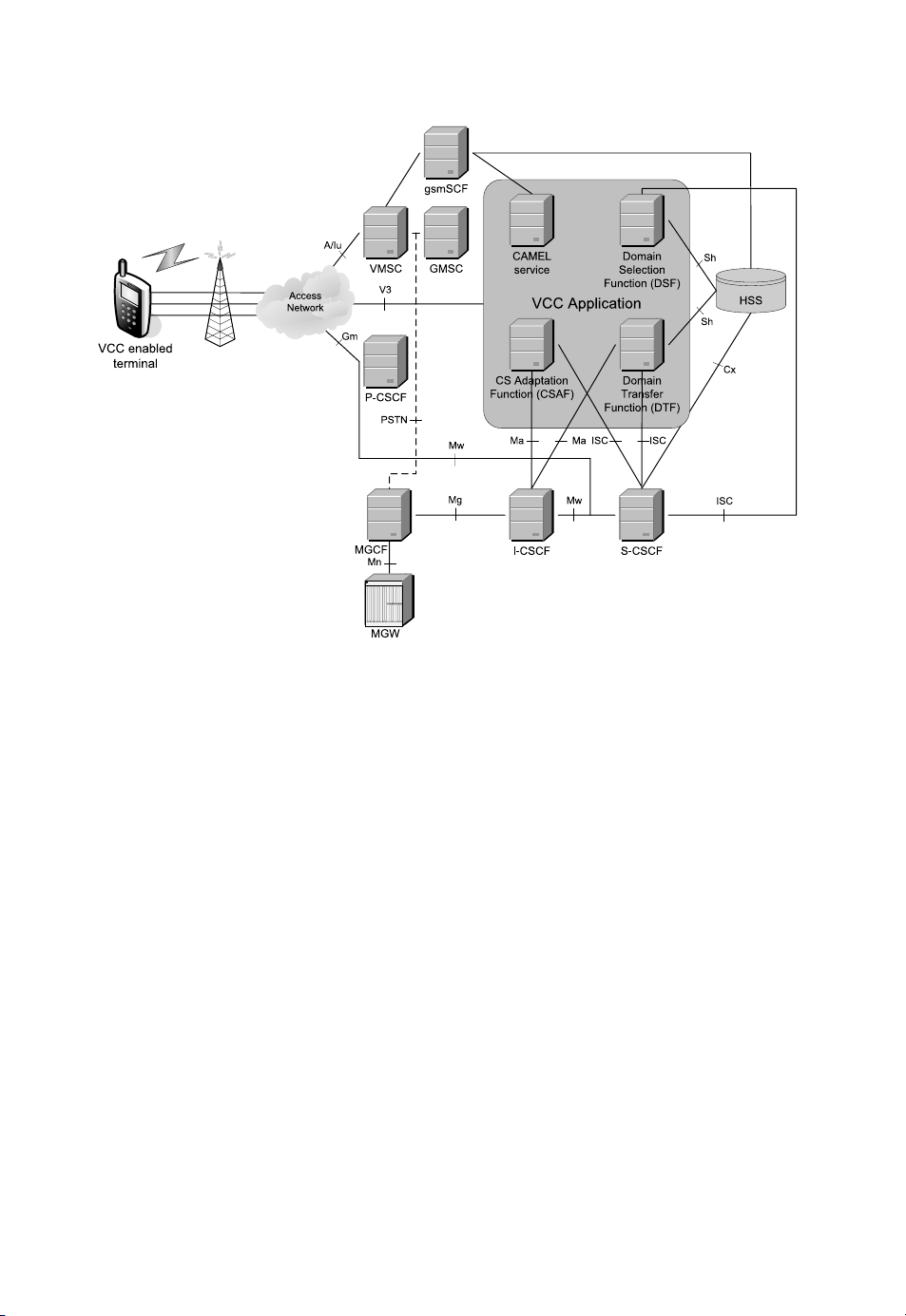
Figure 27.3 shows the general architecture of the VCC application and the related
interfaces. The VCC application is composed of four main functions: the Domain Transfer
Function (DTF), the Domain Selection Function (DSF), the CS Adaptation Function (CSAF),
and the service for Customized Applications for Mobile network Enhanced Logic (CAMEL
service). The interfaces between these four functions are not standardized, so implementa-
tions either implement proprietary interfaces or combine several functions in the same node.
The Domain Transfer Function (DTF) is responsible for executing the transfer of an
access leg from the CS domain to the IMS domain or vice verse. From the point of view of
SIP and IMS, the DTF acts as an Application Server (AS) configured as a Back-to-Back User
Agent (B2BUA) operating as a third-party call controller. In addition, the DTF maintains
policies related to the transfer of domains. The DTF interfaces the S-CSCF via the ISC
interface, the I-CSCF via the Ma, and the HSS via the Sh interface.
The Domain Selection Function (DSF) is involved in terminating calls. The DSF selects
the domain over which the terminating leg of an incoming call will be delivered. To take this
562
CHAPTER 27. VOICE CALL CONTINUITY
Figure 27.3: VCC architecture
decision, the DSF considers operator policy and user preferences. However, it is also helped
by the user’s registration status in the IMS and CS domains, so, for example, if a user is not
registered to the IMS but it is to the CS domain, the call will be delivered over the CS domain.
The DSF interfaces the S-CSCF via the ISC interface and the HSS via the Sh interface.
The CS Adaptation Function (CSAF) is responsible for allocating and de-allocating the
IMRN for CS originated calls. The CSAF communicates call related data from CS to IMS
(such as called an calling party numbers). The CSAF acts as a SIP proxy for CS originated
calls and CS legs established for domain transfer to CS. The CSAF acts as a SIP User Agent
towards the IMS. The CSAF interfaces the S-CSCF via the ISC interface and the I-CSCF via
the Ma interface.
CAMEL is a set of mobile networks standards for providing services in CS networks.
CAMEL is based on the Intelligent Networks (IN) standards. One of the nodes of the CAMEL
architecture is the gsmSCF, which is able to monitor the status of a call and provide certain
services. Well, in VCC, the CAMEL service function provides an alternative for routing calls
using CAMEL services. The functions of the CAMEL service overlap those of the CSAF,
and include allocating IMRN for routing CS calls to IMS, communicating call related data
from CS to IMS (such as called an calling party numbers). However, it also provides unique
functions, such as enforcing the CS redirection policy. The CAMEL service interfaces the
CAMEL gsmSCF via an unspecified interface. This mostly indicates that the CAMEL service
is essentially an extension to the existing gsmSCF.

27.3. REGISTRATION
563
In addition to the interfaces between the individual functions of the VCC application, a
VCC-enabled terminal implements the V3 interface towards the VCC application (or any of
the individual functions). The V3 interface is used for configuration settings and uses XCAP.
We described XCAP in Chapter 17.
Other relevant nodes for the VCC service include a standard PSTN/CS gateway, further
composed of an MGCF and MGW. In addition, a visited MSC has also a role when the access
leg traverses the circuit-switched domain. In the IMS domain, a P-CSCF is also involved
when the access leg uses the IMS.
27.3 Registration
There are no requirements for the VCC terminal with respect registrations. The IMS side
of a VCC-enabled terminal registers to the IMS as per regular procedures (see Section 5.5).
In addition, the CS side of the VCC-enabled terminal performs the regular attachment to the
network.
The VCC application needs to become aware of the IMS registration of the VCC-enabled
terminal. This is done by configuring an initial Filter Criterion that triggers a third-party
registration towards the VCC application when the S-CSCF receives a regular REGISTER
request from the VCC enabled terminal. In addition, the VCC application can subscribe to
the reg event package at the S-CSCF, which keeps the VCC application informed whenever
the VCC-enabled terminal re-registers or deregisters (see Section 5.6 for a description of the
reg event state package). An alternative to notifications of the reg event package is to use
the Sh interface to subscribe to the user’s registration state at the HSS.
27.4 Call Origination and Anchoring
Prior to executing a domain transfer of an ongoing voice call, the call must have been setup
(either in the IMS or the CS domain), and it has to be anchored, so that it can be transferred
to the other domain at a later stage. This section presents call flows for the originating side
indicating the involved entities in the call anchoring and revealing the details of it. The flows
only show the relevant nodes involved in the call anchoring for the originating VCC-enabled
terminal, so, for example, the originating P-CSCF is never shown, neither are any of the
terminating nodes.
27.4.1 IMS Originated Call Leg
Figure 27.4 shows the call flow of an IMS originated call anchored in the network for enabling
a potential domain transfer at a later stage. When the user initiates the call, the VCC-
enabled terminal performs a domain selection that takes into consideration the access network
availability and user preferences. In this example, the result of the domain selection leads to
setting up the call via the IMS domain. Therefore, the VCC-enabled terminal sends a regular
INVITE request (1) that traverses the P-CSCF (not shown in the figure) and other IMS nodes
until it eventually reaches the S-CSCF allocated to the user in the originating home network.
This S-CSCF evaluates the initial filter criteria and as a result of that evaluation, it forwards
the INVITE request (3) to the DTF, as per regular procedures over the ISC interface. Of
importance, the S-CSCF adds a Route header field whose value is a URI that resolves to the
same S-CSCF and contains (e.g., in the user part of the URI) a unique identifier of the dialog.


%20--%3e%3cdefs%3e%3cstyle%3e%20.st0%20{%20fill:%20%23fff;%20}%20.st1%20{%20fill:%20%237800fa;%20}%20%3c/style%3e%3c/defs%3e%3cpath%20class='st1'%20d='M117.78,12.18H43.11c2.9,3.47,4.65,7.94,4.65,12.82,0,5.6-2.3,10.66-6.01,14.29h76.02l7.22-13.56-7.22-13.56Z'/%3e%3cg%3e%3cpath%20class='st0'%20d='M53.58,26.17h-.59v-1.46h.59v-4.96h2.83c1.78,0,2.67.94,2.67,2.82v5.76c0,1.87-.89,2.81-2.67,2.81h-2.83v-4.96ZM55.36,21.37v3.34h1.1v1.46h-1.1v3.34h1.01c.61,0,.91-.37.91-1.1v-5.93c0-.74-.3-1.1-.91-1.1h-1.01Z'/%3e%3cpath%20class='st0'%20d='M65.99,31.14h-1.8l-.31-2.07h-2.19l-.31,2.07h-1.64l1.82-11.39h2.62l1.82,11.39ZM65.28,18.04c-.25.46-.51.77-.75.94-.21.15-.47.22-.79.22-.26,0-.57-.07-.92-.22l-.38-.15c-.14-.05-.26-.07-.37-.07-.3,0-.53.18-.71.54l-.91-.68c.25-.46.51-.77.75-.94.21-.14.48-.21.79-.21.26,0,.57.07.92.21l.38.15c.14.05.26.07.37.07.3,0,.53-.18.71-.54l.91.68ZM61.91,27.52h1.73l-.87-5.76-.87,5.76Z'/%3e%3cpath%20class='st0'%20d='M74.53,26.89v1.52c0,1.91-.89,2.86-2.67,2.86s-2.67-.95-2.67-2.86v-5.93c0-1.91.89-2.86,2.67-2.86s2.67.95,2.67,2.86v1.11h-1.69v-1.22c0-.75-.31-1.12-.93-1.12s-.93.37-.93,1.12v6.15c0,.74.31,1.11.93,1.11s.93-.37.93-1.11v-1.63h1.69Z'/%3e%3cpath%20class='st0'%20d='M81.4,31.14h-1.8l-.31-2.07h-2.19l-.31,2.07h-1.64l1.82-11.39h2.62l1.82,11.39ZM75.9,19.2l1.52-1.91h1.71l1.51,1.91h-1.61l-.76-.95-.75.95h-1.61ZM77.32,27.52h1.73l-.87-5.76-.87,5.76ZM83.1,15.99l-1.76,1.91h-1.26l1.17-1.91h1.86Z'/%3e%3cpath%20class='st0'%20d='M84.86,19.75c1.78,0,2.67.94,2.67,2.82v1.48c0,1.87-.89,2.81-2.67,2.81h-.85v4.28h-1.79v-11.39h2.64ZM84.01,21.37v3.86h.85c.58,0,.87-.36.87-1.08v-1.71c0-.71-.29-1.07-.87-1.07h-.85Z'/%3e%3cpath%20class='st0'%20d='M93.51,19.75c1.78,0,2.67.94,2.67,2.82v1.48c0,1.87-.89,2.81-2.67,2.81h-.85v4.28h-1.79v-11.39h2.64ZM92.66,21.37v3.86h.85c.58,0,.87-.36.87-1.08v-1.71c0-.71-.29-1.07-.87-1.07h-.85Z'/%3e%3cpath%20class='st0'%20d='M98.8,31.14h-1.79v-11.39h1.79v4.88h2.03v-4.88h1.83v11.39h-1.83v-4.88h-2.03v4.88Z'/%3e%3cpath%20class='st0'%20d='M105.36,24.55h2.46v1.62h-2.46v3.34h3.09v1.63h-4.88v-11.39h4.88v1.63h-3.09v3.18ZM108.17,17.29l-1.76,1.91h-1.26l1.17-1.91h1.86Z'/%3e%3cpath%20class='st0'%20d='M112.2,19.75c1.78,0,2.67.94,2.67,2.82v1.48c0,1.87-.89,2.81-2.67,2.81h-.85v4.28h-1.79v-11.39h2.64ZM111.35,21.37v3.86h.85c.58,0,.87-.36.87-1.08v-1.71c0-.71-.29-1.07-.87-1.07h-.85Z'/%3e%3c/g%3e%3ccircle%20class='st1'%20cx='25'%20cy='25'%20r='20'/%3e%3cpath%20class='st0'%20d='M32.78,19.27c2.92,0,4.43,2.55,5.28,5.33l.71,2.17c.14.38-.33.75-.71.75h-5.61c.19-.33.24-.71.09-1.08l-.75-2.45c-.43-1.32-.99-2.64-1.79-3.77.75-.57,1.65-.94,2.78-.94h0ZM25,18.38c3.25,0,4.9,2.78,5.89,5.89l.76,2.45c.14.42-.33.8-.8.8h-11.69c-.42,0-.94-.38-.8-.8l.75-2.45c.99-3.11,2.64-5.89,5.89-5.89h0ZM25,11.35c1.74,0,3.11,1.37,3.11,3.11s-1.37,3.11-3.11,3.11-3.11-1.41-3.11-3.11,1.41-3.11,3.11-3.11h0ZM17.27,19.27c1.08,0,1.98.38,2.73.94-.8,1.13-1.37,2.45-1.74,3.77l-.8,2.45c-.14.38-.05.75.09,1.08h-5.56c-.42,0-.9-.38-.75-.75l.71-2.17c.9-2.78,2.41-5.33,5.33-5.33h0ZM17.27,12.91c1.51,0,2.78,1.27,2.78,2.83s-1.27,2.83-2.78,2.83-2.83-1.27-2.83-2.83,1.27-2.83,2.83-2.83h0ZM32.78,12.91c1.56,0,2.78,1.27,2.78,2.83s-1.23,2.83-2.78,2.83-2.83-1.27-2.83-2.83,1.27-2.83,2.83-2.83h0ZM27.07,28.56v.09c0,.57-.24,1.08-.61,1.46h0v.05c-.38.33-.9.57-1.46.57s-1.08-.24-1.46-.61h0c-.38-.38-.61-.9-.61-1.46v-.09h1.41v.09c0,.19.05.38.19.47v.05c.09.09.28.19.47.19s.38-.09.47-.19v-.05c.14-.09.24-.28.24-.47t-.05-.09h1.41ZM30.99,28.56v.09c0,1.65-.66,3.16-1.74,4.24-1.08,1.08-2.59,1.79-4.24,1.79s-3.16-.71-4.24-1.79l-.05-.05c-1.04-1.08-1.7-2.55-1.7-4.2v-.09h1.41v.09c0,1.27.47,2.4,1.27,3.25h.05c.85.85,1.98,1.37,3.25,1.37s2.4-.52,3.25-1.37c.85-.8,1.37-1.98,1.37-3.25v-.09h1.37ZM34.99,28.56v.09c0,2.78-1.13,5.28-2.92,7.07-1.79,1.79-4.29,2.92-7.07,2.92s-5.23-1.13-7.07-2.92c-1.79-1.79-2.92-4.29-2.92-7.07v-.09h1.41v.09c0,2.4.94,4.53,2.5,6.08,1.56,1.56,3.72,2.5,6.08,2.5s4.52-.94,6.08-2.5c1.56-1.56,2.5-3.68,2.5-6.08v-.09h1.41Z'/%3e%3c/svg%3e)