
ISSN: 2615-9740
JOURNAL OF TECHNICAL EDUCATION SCIENCE
Ho Chi Minh City University of Technology and Education
Website: https://jte.edu.vn
Email: jte@hcmute.edu.vn
JTE, Volume 19, Issue 06, 2024
1
Wrist Exoskeleton Device with a Novel Cable Drive Solution
Minh Thong NGUYEN1, Van Hau TRAN1, Tan Hung HUYNH2,
Viet Anh Dung CAI3* , Thanh Tung LE3
1Eastern International University, Vietnam
2Ecole Centrale de Lyon, 36 Av. Guy de Collongue, 69134 Écully, France
3Ho Chi Minh City University of Technology and Education, Vietnam
*Corresponding author. Email: dungcva@hcmute.edu.vn
ARTICLE INFO
ABSTRACT
Received:
28/11/2023
This paper presents the design of a lower limb exoskeleton made for the
purpose of wrist joint rehabilitation. The authors use the exoskeleton
structure in order to cope with the user’s upper-limb kinematics and to
provide motion to the wrist joint when the arm is in any possible spatial
configuration. To reduce the inertia of the mechanical structure, the motors
are fixed at the back of the user and the power transmission is realized via
a cable drive transmission. Two elastic cables are used to control the
flexion/extension movement of the wrist joint. The tensions inside the
elastic cables are controlled within the use of 2 torque sensors. By using
two DC motors, the actuation unit can act like human tendons and provides
more natural assistance motion. At the output axis, a third torque sensor is
used to allow the control of the interaction between the mechanism and the
user’s wrist joint.
Revised:
14/05/2024
Accepted:
24/07/2024
Published:
28/12/2024
KEYWORDS
Wrist exoskeleton;
Impedance control;
Cable drive;
Self-adjusting mechanism;
Torque sensor.
Doi: https://doi.org/10.54644/jte.2024.1499
Copyright © JTE. This is an open access article distributed under the terms and conditions of the Creative Commons Attribution-NonCommercial 4.0
International License which permits unrestricted use, distribution, and reproduction in any medium for non-commercial purpose, provided the original work is
properly cited.
1. Introduction
Today in Vietnam, stroke stands as a leading cause to both mortality and incapacitation. Reportedly,
stroke incidence rate is around 0.16% for 2021 [1]. Survivors of stroke often contend with a loss of
physical prowess and typically require therapeutic interventions to regain their mobility. Similarly,
patients at ICU also suffer joint stiff after a long period of immobility, which is one of the main causes
of upper limb/ lower limb impairment. Therefore, functional rehabilitation exercises developed for the
post stroke / ICU patients is primordial in order to allow the patients to progressively regain normal
functions of their sensorimotor system [2], [3].
Continuous passive motion exercises can be indicated at the early phases of rehabilitation to prevent
joint stiff and maintain joint’s range of motion [4], [5], [6] with similar results compared to exercises
realized by professional therapy [7]. Today, exercises using knee CPM [8], [9] as well as upper-limb
CPM [10], [11] or cycling devices [12], [13] were investigated by researchers. These devices generally
provide passive motions (i.e. motion controlled in velocity, in open-loop or close-loop) to the targeted
anatomical joints. Force control is generally not mentioned in CPM literature as these machines are
generally used in early phases where the patients’ joints are still so weak that resistive exercises are not
required yet.
In this paper, the authors explore the possibility of using exoskeleton to realize rehabilitation
exercises on patient’s wrist joint. The system is composed of an exoskeletal structure and a cable drive
system allowing the control of the targeted joint at distance. The use of torque sensors allows the
programing of both passive and active exercises on the device [14].
Cable drive solutions enables the separation of the motors unit from the exoskeleton's mechanical
frame by moving it to a fixed base, thus reducing the inertia of the mechanical frame. This solution also
allows realizing force control using series-elasticity technique [15]. Flexible cables can be used instead
of output springs, which at the same time provide a higher level of safety for the system.

ISSN: 2615-9740
JOURNAL OF TECHNICAL EDUCATION SCIENCE
Ho Chi Minh City University of Technology and Education
Website: https://jte.edu.vn
Email: jte@hcmute.edu.vn
JTE, Volume 19, Issue 06, 2024
2
Since 2000s, Bowden Cables systems were developed by researchers for active exoskeletons [16],
[17]. Bowden Cable drive solution uses one single motor and two cables functioning in push-pull mode.
The tensions inside the cables are controlled by the springs, which require a manual adjusting procedure
before using. In addition, the dynamic performance of the system is defined by the motor, which in
general provides a limited frequency band-width if powerful. Coupling a small motor to the principal
one can help overcome this issue [18].
In this paper, the authors present a novel solution for the design of wrist exoskeleton using a cable
drive system with 2 DC motors, that are controlled in torque via torque sensors. With this solution, the
tensions inside the cables can be controlled. The output torque is generated by controlling the difference
between the 2 cables tensions. The mechanical design was realized following the rules for exoskeleton
design established in [19]. The system is controlled both in torque and in position. Control solution is
presented in details and first experiments results are presented and discussed.
2. Materials and Methods
2.1. Cable drive solution
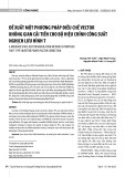
The cable drive solution [20] that is being used for our system includes 2 DC motors controlling
separately the tensions of 2 flexible cables which are fixed onto the output axis (see figure 1). By setting
the 2 tensions set-points at 2 different levels, one can control the output torque at the output axis. Three
torque sensors were used: 2 for the control of the cables tensions and 1 at the output axis to control the
interaction with the user.
Figure 1. Prototype of the cable-drive actuation unit [20].
In our wrist exoskeleton design, the output axis is placed at the user’s wrist level and the 2 motors
are fixed on a base that is located at the user’s back. This design allows to reduce the inertia of the whole
system to a minimum value. Furthermore, the output axis can be nearly anywhere in space and is not
necessarily parallel to the 2 motors’ axes.
2.2. Wrist joint exoskeleton design
The design of the exoskeleton was realized follow the design rule established in [19] to create a
“transparent mechanical system” that allows the user to naturally move the upper-limb, which is attached
to the device, without feeling constraint by the mechanical system.
According to this rule, for the upper limb, the mechanism should be designed in following order: the
shoulder joint part, followed by the elbow joint part, and finally the wrist joint part. Each part should be
secured to user’s limb, creating a kinematic loop. The degree of freedom of the kinematic loop
(anatomical joint - mechanism) should be equal to 1, that allows the joint the move freely. Figure 2, 3
and 4 illustrates the design solutions for the shoulder, the elbow and the wrist joints.
Three successive rotational joints forming a mechanism in series is used at the shoulder level (see
figure 2). The 3 axes are intersecting at one single centre of rotation to form an equivalence of spherical

ISSN: 2615-9740
JOURNAL OF TECHNICAL EDUCATION SCIENCE
Ho Chi Minh City University of Technology and Education
Website: https://jte.edu.vn
Email: jte@hcmute.edu.vn
JTE, Volume 19, Issue 06, 2024
3
joint. Right after the 3rd rotational joint, a slider joint is added in order to support the attach mechanism
connecting the structure to the user’s upper arm.
Figure 2. Kinematic solution for the shoulder.
Figure 3. Design solution for the elbow.
At the elbow level, a rotational joint is used to create flexion/extension movement, follow by a
slider joint that allow to adjust to the user’s forearm length.
Figure 4. Design solution for the wrist.
The second rotational degree of freedom is composed by a rolling mechanism that produces motion
on a circular rail. This solution allows to shift the axis of motion inside the circular rail, aligning it to
the elbow’s internal/external rotation axis (see figure 3).

ISSN: 2615-9740
JOURNAL OF TECHNICAL EDUCATION SCIENCE
Ho Chi Minh City University of Technology and Education
Website: https://jte.edu.vn
Email: jte@hcmute.edu.vn
JTE, Volume 19, Issue 06, 2024
4
At the wrist level, one single axis of rotation is used, which is the actuated output axis. 2 pulleys are
fixed at this output axis, that allow the fixation of the 2 flexible cables. A torque sensor, as well as a
precision potentiometer are also placed at this same axis to measure the interactive torque and the
displacement of the wrist joint.
Figure 5 illustrates the 3D design of the whole system. In this system, the actuation is realized at the
wrist level. However, other anatomical joint (shoulder & elbow) can be easily actuated as well by simply
introducing the system of torque sensor and pulleys at the targeted joints. We introduced a system of
fixture knobs at the non-actuated joints to balance the mechanical structure’s weight and to immobilize
the exoskeletal structure when the exercises are being realized on the targeted joint (here is the wrist
joint).
Figure 5. 3D CAD Model of the whole system.
Figure 6. Parameter setting of the upper-limb exoskeleton, using modified D.H. Notation.
Table 1. Modified D.H. parameters
Matrix
αi
ai
θi
di
T01
0
0
θ1
0
T12
-π/2
0
θ2-π/2
0
T23
-π/2
0
θ3
l2
T34
0
l3
θ4+π/2
0
T45
π/2
0
-π/2
r5
T56
0
l5
θ6
l6
T67
-π/2
0
θ7
0

ISSN: 2615-9740
JOURNAL OF TECHNICAL EDUCATION SCIENCE
Ho Chi Minh City University of Technology and Education
Website: https://jte.edu.vn
Email: jte@hcmute.edu.vn
JTE, Volume 19, Issue 06, 2024
5
The kinematic scheme of the whole system is shown in figure 6. The parameter setting is built using
Modified D.H. Convention. The external structure of the system has in total 7 degrees of freedom which
is equal to the d.o.f. of a human arm. The modified D.H. parameters are presented in table 1.
2.3. Control solution
Figure 7. The system control scheme
Figure 7 illustrates the control solution of the system. The interactive torque M3 is measured by the
torque sensor fixed at the output axis z7. This measure is the feedback signal that allows the
determination the torque set-point signal M0 for the control of the 2 DC motors torques. M0 is computed
by a PD controller. The torque set-points M1 and M2 of the 2 DC motors can then be determined in
function of M0 using following formula:
0
03
2 0 2
3
11
0
.
.
FR
R
FR
R
M
M
M
M
(1)
Here M1 and M2 are the torque set-points for the 2 DC motors. F0 is the initial tension force inside
the cables, that can be set by the operator and is controlled by the actuation units. Ri is the radius of the
pulleys. In case that R1 = R2 = R3 = R (i.e. all the 3 pulleys, 2 at the 2 motors’axes and 1 at the wrist
output axis, are similar), we have:
00
2 0 0
1.
.
F R M
F R M
M
M
(2)
When there is no interaction between the user and the system (M3 = 0), the 2 torque set-points M1
and M2 are both equal to the torque value
0.FR
that generates the cable’s tension. Only the tensions
inside the cables are in control. Different operational modes can be defined for the system: Following
mode (Zero Interactive torque), Resistive mode and Assistive mode. The first 2 modes can be realized
using the law of impedance control [14], [21]-[23], modeled as follow:


![Chương trình đào tạo cơ bản Năng lượng điện mặt trời mái nhà [mới nhất]](https://cdn.tailieu.vn/images/document/thumbnail/2026/20260126/cristianoronaldo02/135x160/21211769418986.jpg)

![Chương trình đào tạo cơ bản Năng lượng gió [Tối ưu SEO]](https://cdn.tailieu.vn/images/document/thumbnail/2026/20260126/cristianoronaldo02/135x160/53881769418987.jpg)


