3-7
Simpo PDF Merge and Split Unregistered Version - http://www.simpopdf.com
Simpo PDF Merge and Split Unregistered Version - http://www.simpopdf.com
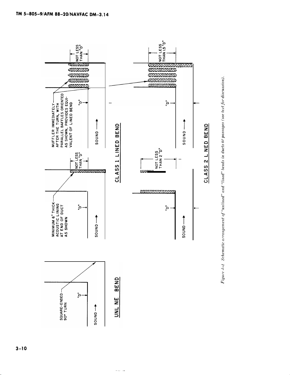
b. “Lined” and “unlined” bends in turbine
stacks. When a long duct or passageway contains a
square-ended 90° turn, there is a tendency for
sound traveling in that duct to be reflected back to-
ward the direction from which it came. Because
high-frequency sound is more “directional” (be-
haves more nearly as a beam of light), it is more
readily reflected back by the end wall of the 90°
turn and less sound is transmitted around the cor-
ner. Low-frequency sound “bends” around the turn
more readily, so this reflection effect is less pro-
nounced. The attenuation provided by a square-
ended 90° turn can be
adding a thick lining of acoustic absorption materi-
al at the end of the turn (facing the oncoming sound
wave), extending into the duct past the turn for a
length of one or two times the average width of the
duct. A long muffler, located immediately past the
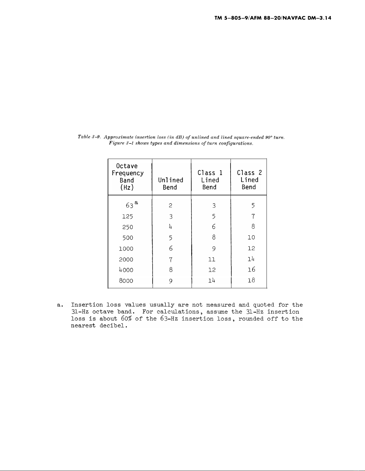
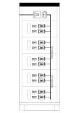
turn, also serves to simulate a lined bend. Table
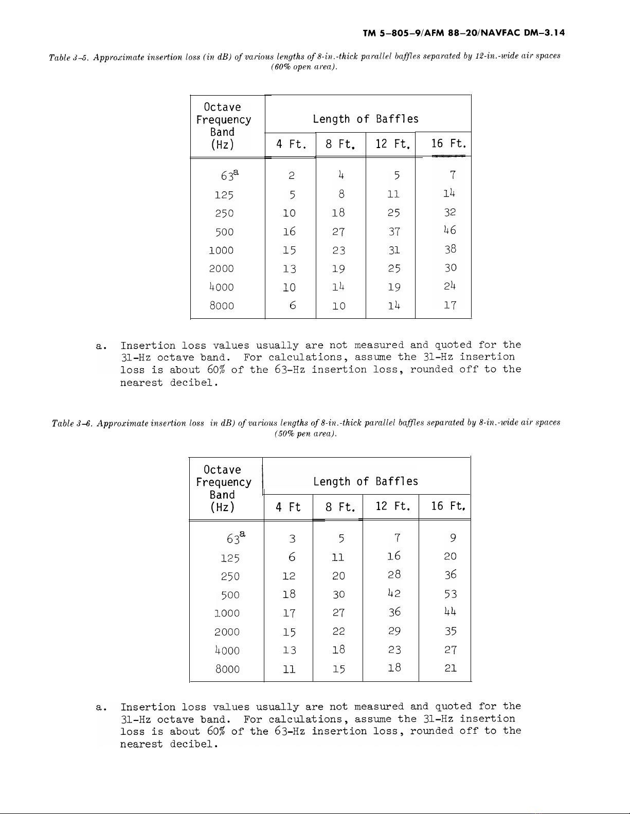
3–9 gives the estimated insertion loss of unlined
and lined bends, and figure 3–1 shows schematical-
ly the bend configurations. The orientation of the
parallel baffles of a muffler located just past a turn
should be as shown in figure 3–1 to achieve the
Class 1 and Class 2 lined bend effects.
increased noticeably by
3-9
Simpo PDF Merge and Split Unregistered Version - http://www.simpopdf.com
Simpo PDF Merge and Split Unregistered Version - http://www.simpopdf.com
Turning vanes in the 90° square turn reduce the in-
sertion loss values. If turning vanes are used, only
one-half the insertion loss values of table 3–9 may
be used for the 63- through 500-Hz bands and only
one-fourth the values for the 1000- through
8000-Hz bands. When a muffler is used at the turn,
full attenuation of the muffler is realized as well as
the additional loss due to the lined turn.
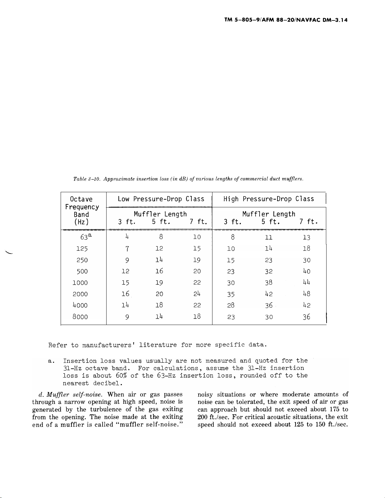
c. Ventilation-duct mufflers. For ducted air-
handling, ventilation, or air-conditioning systems,
packaged duct mufflers can be purchased directly
from reputable acoustical products suppliers. Their
catalogs show the available dimensions and inser-
tion losses provided in their standard rectangular
and circular cross-section mufflers. These pack-
aged duct mufflers are sold by manufacturers in
3-ft., 5-ft., and 7-ft. lengths. They are also usually
available in two or three “classes,” depending on
attenuation. The mufflers of the higher insertion-
l0SS class typically have only about 25% to 35%
open area, with the remainder of the space filled
with absorption material. The lower insertion-loss
classes have about 50% open area. The mufflers
with the larger open area have less pressure drop
and are known as “low-pressure-drop units. ” The
mufflers with the smaller open area are known as
“high-pressure-drop units. ” When ordering special-
purpose mufflers, one should state the speed and
the temperature of the air or gas flow, as these
may require special surface protection and special
acoustic filler materials. The approximate insertion
losses of a representative group of ventilation-duct
mufflers are given in table 3–10. Individual suppli-
ers can give data for their specific products.
There is no precise schedule of self-noise as a func- For
tion of exit speed for large mufflers, but the follow- sity
ing rules-of-thumb for exhaust stacks of turbine en- flow
gines are offered. For installations in relatively
mal
hot exhausts, the exhaust gas is of lower den-
and consequently has a higher total volume
for a given mass flow than would exist at nor-
ambient temperature. The manufacturers of
3–1 1
Simpo PDF Merge and Split Unregistered Version - http://www.simpopdf.com
![Bộ tài liệu Đào tạo nhân viên chăm sóc khách hàng tại đơn vị phân phối và bán lẻ điện [Chuẩn nhất]](https://cdn.tailieu.vn/images/document/thumbnail/2025/20251001/kimphuong1001/135x160/3921759294552.jpg)

![Thiết kế tụ điện và đi dây [chuẩn nhất]](https://cdn.tailieu.vn/images/document/thumbnail/2018/20180612/truonganhshun/135x160/9041528775303.jpg)

![Cân bằng công suất tác dụng và phản kháng trong hệ thống điện: Chương 11 [Hướng dẫn chi tiết]](https://cdn.tailieu.vn/images/document/thumbnail/2015/20150806/hoangnhu220191/135x160/753133488.jpg)
![Tài liệu lớp thực hành Thiết kế M&E [mới nhất]](https://cdn.tailieu.vn/images/document/thumbnail/2015/20150515/ducxt1995/135x160/1757147_269.jpg)


![Giáo trình Trang bị điện nước (TC) - Trường Cao đẳng Công nghiệp Thanh Hóa [Ngành Điện nước]](https://cdn.tailieu.vn/images/document/thumbnail/2026/20260511/hoatrami2026/135x160/14221778681890.jpg)


