(f) Deformation properties of masonry
It is stated that the stress-strain relationship for masonry is parabolic in
form but may for design purposes be assumed as an approximation to be
rectangular or parabolic-rectangular. The latter is a borrowing from
reinforced concrete practice and may not be applicable to all kinds of
masonry.
The modulus of elasticity to be assumed is the secant modulus at the
serviceability limit, i.e. at one-third of the maximum load. Where the results
of tests in accordance with the relevant European standard are not available
E under service conditions and for use in structural analysis may be taken
as 1000fk. It is further recommended that the E value should be multiplied
by a factor of 0.6 when used in determining the serviceability limit state. A
reduced E value is also to be adopted in relation to long-term loads. This
may be estimated with reference to creep data.
In the absence of more precise data, the shear modulus may be
assumed to be 40% of E.
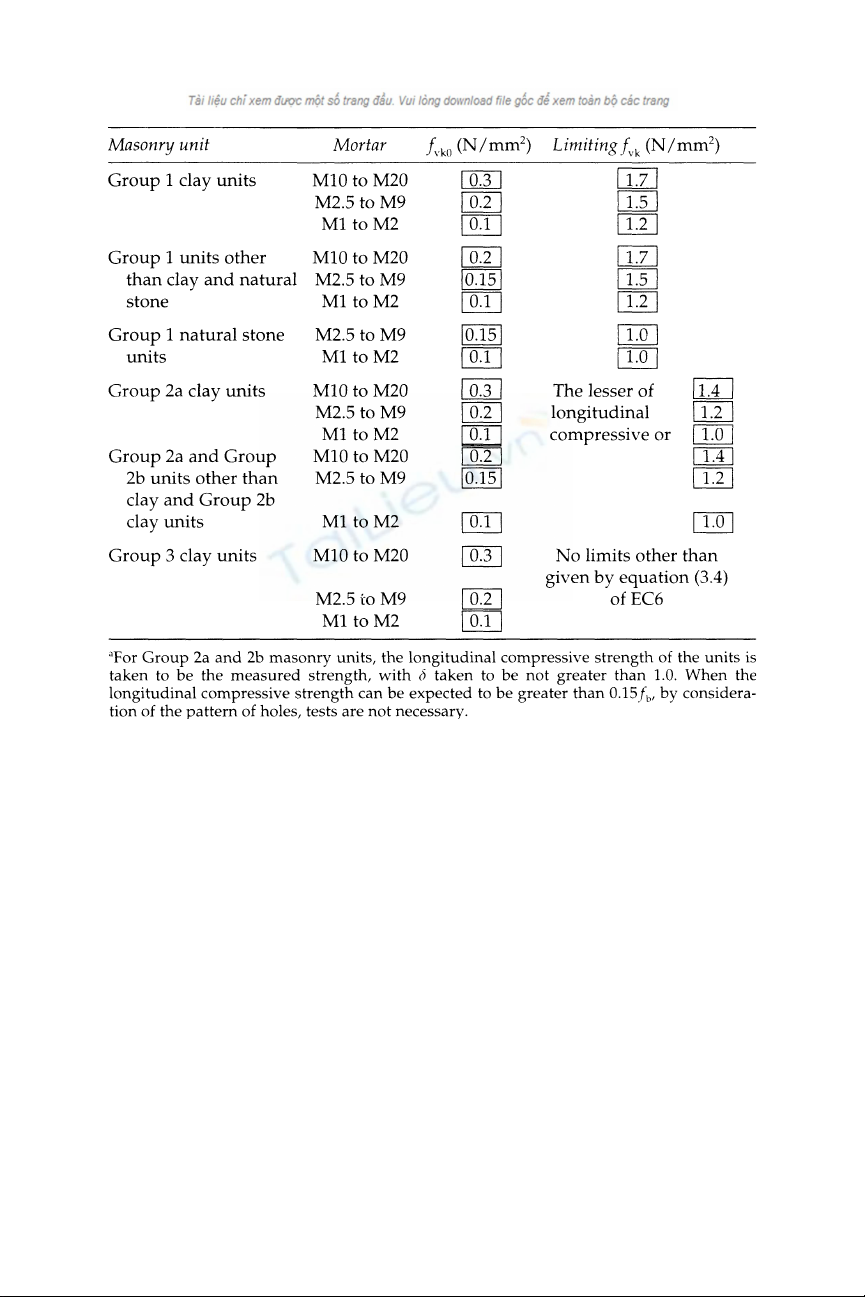
Table 4.7 Values of fvk0 and limiting values of fvk for general-purpose mortar (EC6)a
©2004 Taylor & Francis
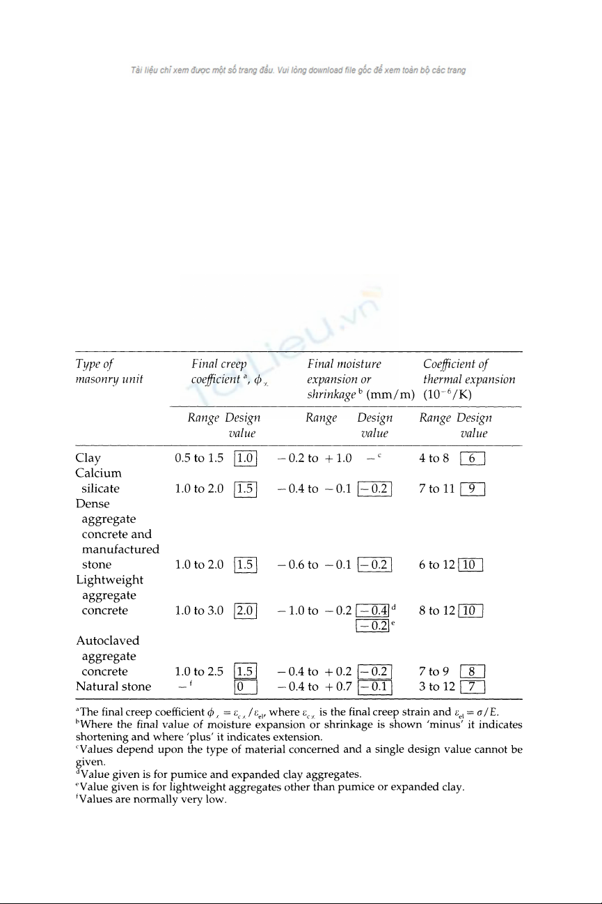
(g) Creep, shrinkage and thermal expansion
A table is provided of approximate values to be used in the calculation of
creep, shrinkage and thermal effects. However, as may be seen from
Table 4.8 these values are given in terms of rather wide ranges so that it is
difficult to apply them in particular cases in the absence of test results for
the materials being used.
4.4.4 Section 4: design of masonry
(a) General stability
Initial provisions of this section call for overall stability of the structure to
be considered. The plan layout of the building and the interconnection of
Table 4.8 Deformation properties of unreinforced masonry made with
generalpurpose mortar (EC6).
©2004 Taylor & Francis
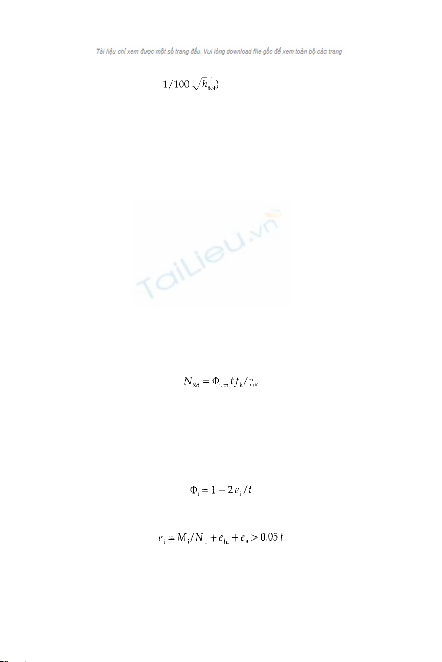
elements must be such as to prevent sway. The possible effects of
imperfections should be allowed for by assuming that the structure is
inclined at an angle of to the vertical where htot is the total
height of the building. One designer must, unambiguously, be
responsible for ensuring overall stability.
(b) Accidental damage
Buildings are required to be designed in such a way that there is a
‘reasonable probability’ that they will not collapse catastrophically under
the effect of misuse or accident and that the extent of damage will not be
disproportionate to the cause. This is to be achieved by considering the
removal of essential loadbearing members or designing them to resist the
effects of accidental actions. However, no specific rules relating to these
requirements are given.
(c) Design of structural members
The design of members has to be such that no damage is caused to
facings, finishes, etc., but it may be assumed that the serviceability limit
state is satisfied if the ultimate limit state is verified. It is also required
that the stability of the structure or of individual walls is ensured during
construction.
Subject to detailed provisions relating to the type of construction, the
design vertical load resistance per unit length, NRd, of an unreinforced
masonry wall is calculated from the following expression:
(4.12)
where Φi,m is a capacity reduction factor allowing for the effects of
slenderness and eccentricity (Φi applies to the top and bottom of the wall;
Φm applies to the mid-height and is obtained from the graph shown in
Fig. 4.6), t is the thickness of the wall, fk is the characteristic compressive
strength of the masonry and
m is the partial safety factor for the
material.
The capacity reduction factor Φi is given by:
(4.13)
where ei is the eccentricity at the top or bottom of the wall calculated
from
(4.14)
where Mi and Ni are respectively the design bending moment and
vertical load at the top or bottom of the wall and ehi and ea are
©2004 Taylor & Francis
Rules are given for the assessment of the effective height of a wall. In
general, walls restrained top and bottom by reinforced concrete slabs are
assumed to have an effective height of 0.75×actual height. If similarly
restrained by timber floors the effective height is equal to the actual
height. Formulae are given for making allowance for restraint on vertical
edges where this is known to be effective. Allowance may have to be
made for the presence of openings, chases and recesses in walls.
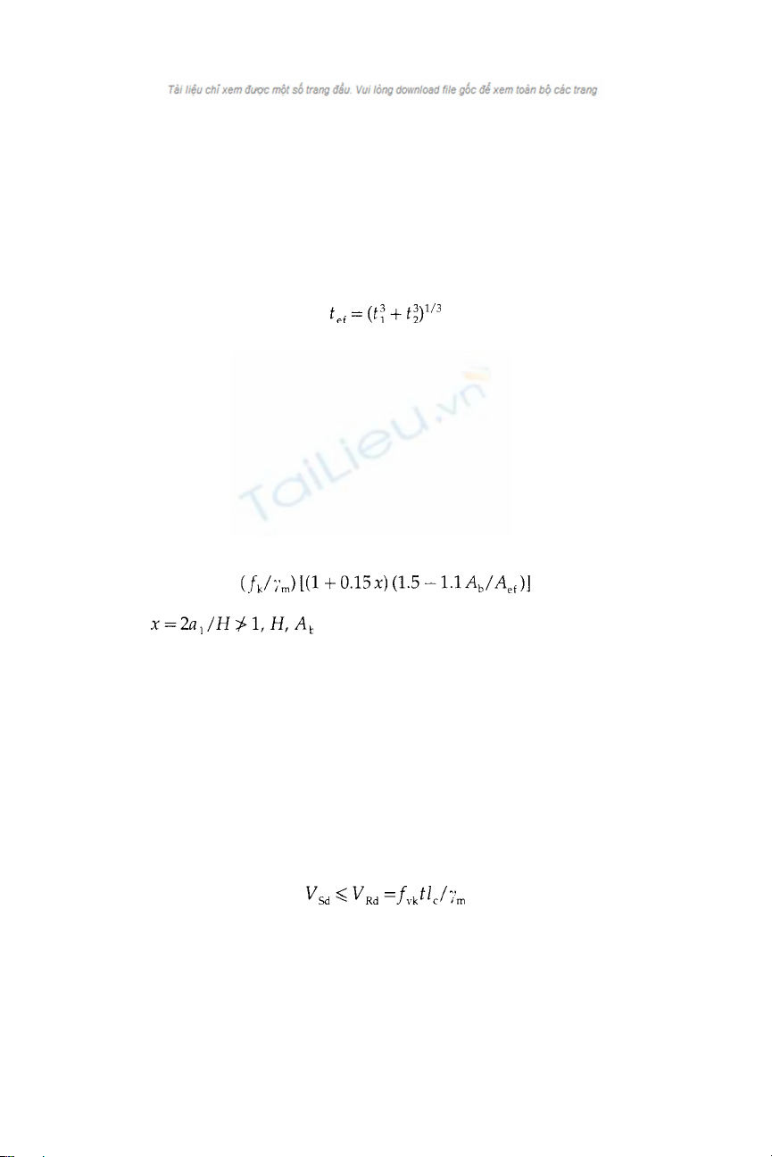
The effective thickness of a wall of ‘solid’ construction is equal to the
actual thickness whilst that of a cavity wall is
(4.18)
where t1 and t2 are the thicknesses of the leaves. Some qualifications of
this rule are applicable if only one leaf is loaded.
The out-of-plane eccentricity of the loading on a wall is to be assessed
having regard to the material properties and the principles of mechanics.
A possible, simplified method for doing this is given in an Annex, but
presumably any other valid method would be permissible.
An increase in the design load resistance of an unreinforced wall
subjected to concentrated loading may be allowed. For walls built with
units having a limited degree of perforation, the maximum design
compressive stress in the locality of a beam bearing should not exceed
(4.19)
where and Aef are as shown in Fig. 4.7.
This value should be greater than the design strength fk/
m but not
greater than 1.25 times the design strength when x=0 or 1.5 times this
value when x=1.5. No increase is permitted in the case of masonry built
with perforated units or in shell-bedded masonry.
(d) Design of shear walls
Rather lengthy provisions are set out regarding the conditions which
may be assumed in the calculation of the resistance of shear walls but the
essential requirement is that the design value of the applied shear load,
Vsd, must not exceed the design shear resistance, VRd, i.e.
(4.20)
where fvk is the characteristic shear strength of the masonry, t is the
thickness of the masonry and lc is the compressed length of the wall
(ignoring any part in tension).
Distribution of shear forces amongst interconnected walls may be by
elastic analysis and it would appear that the effect of contiguous floor
©2004 Taylor & Francis
provisions for shear reinforcement are, however, more elaborate and
provide for the possible inclusion of diagonal reinforcement, which is
uncommon in reinforced masonry sections.
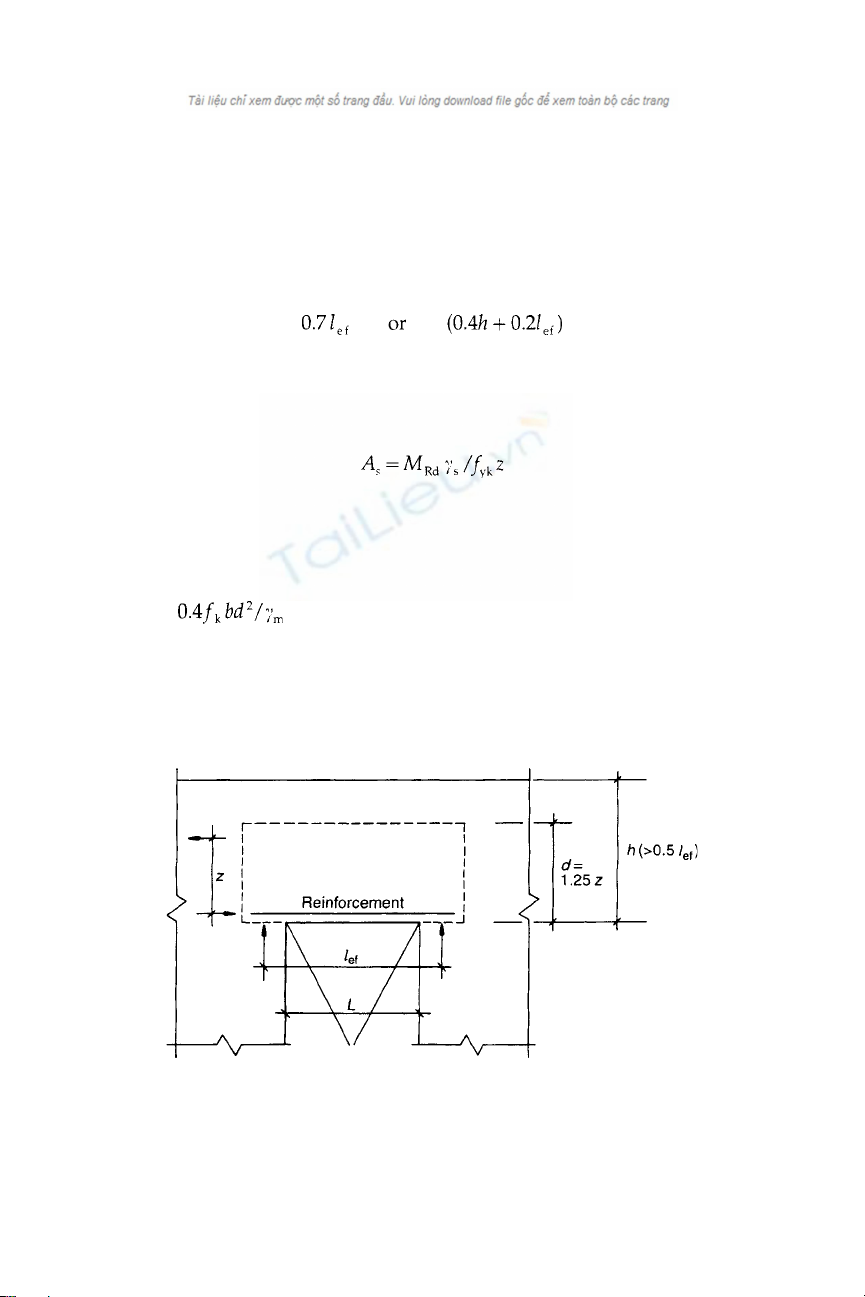
A section is included on the design of reinforced masonry deep beams
which may be carried out by an appropriate structural theory or by an
approximate theory which is set out in some detail. In this method the
lever arm, z, for calculating the design moment of resistance is, referring
to Fig. 4.8, the lesser of
(4.21)
where lef is the effective span, taken to be 1.15×the clear span, and h is the
clear height of the wall.
The reinforcement As required in the bottom of the deep beam is then
(4.22)
where MRd is the design bending moment and fyk is the characteristic
strength of the reinforcement. The code also calls for additional nominal
bed-joint reinforcement to a height of 0.5l above the main reinforcement
or 0.5d, whichever is the lesser, ‘to resist cracking’. In this case, an upper
limit of is specified although a compression failure in a deep
beam seems very improbable.
Other clauses deal with serviceability and with prestressed masonry.
The latter, however, refer only to ENV 1992–1–1 which is the Eurocode
for prestressed concrete and give no detailed guidance.
Fig. 4.8 Representation of a deep beam.
©2004 Taylor & Francis


![Bản vẽ kiến trúc: Tổng hợp trong hồ sơ kỹ thuật [Chuẩn SEO]](https://cdn.tailieu.vn/images/document/thumbnail/2017/20170625/hoaibao05021997/135x160/3811498376242.jpg)
![Bản vẽ thiết kế nhà biệt thự: Chuẩn nhất, [Năm]](https://cdn.tailieu.vn/images/document/thumbnail/2017/20170623/hoaibao05021997/135x160/4501498215207.jpg)


![Gia Công & Lắp Đặt Cốt Thép: Kỹ Thuật Xây Dựng Bê Tông [Chuẩn Nhất]](https://cdn.tailieu.vn/images/document/thumbnail/2026/20260531/alfredodistefano10/135x160/58891780257145.jpg)
![Gia Công Ván Khuôn: Lắp Dựng, Tháo Dỡ và Kỹ Thuật Xây Dựng [Chi Tiết A-Z]](https://cdn.tailieu.vn/images/document/thumbnail/2026/20260531/alfredodistefano10/135x160/4261780257147.jpg)


%20--%3e%3cdefs%3e%3cstyle%3e%20.st0%20{%20fill:%20%23fff;%20}%20.st1%20{%20fill:%20%237800fa;%20}%20%3c/style%3e%3c/defs%3e%3cpath%20class='st1'%20d='M117.78,12.18H43.11c2.9,3.47,4.65,7.94,4.65,12.82,0,5.6-2.3,10.66-6.01,14.29h76.02l7.22-13.56-7.22-13.56Z'/%3e%3cg%3e%3cpath%20class='st0'%20d='M53.58,26.17h-.59v-1.46h.59v-4.96h2.83c1.78,0,2.67.94,2.67,2.82v5.76c0,1.87-.89,2.81-2.67,2.81h-2.83v-4.96ZM55.36,21.37v3.34h1.1v1.46h-1.1v3.34h1.01c.61,0,.91-.37.91-1.1v-5.93c0-.74-.3-1.1-.91-1.1h-1.01Z'/%3e%3cpath%20class='st0'%20d='M65.99,31.14h-1.8l-.31-2.07h-2.19l-.31,2.07h-1.64l1.82-11.39h2.62l1.82,11.39ZM65.28,18.04c-.25.46-.51.77-.75.94-.21.15-.47.22-.79.22-.26,0-.57-.07-.92-.22l-.38-.15c-.14-.05-.26-.07-.37-.07-.3,0-.53.18-.71.54l-.91-.68c.25-.46.51-.77.75-.94.21-.14.48-.21.79-.21.26,0,.57.07.92.21l.38.15c.14.05.26.07.37.07.3,0,.53-.18.71-.54l.91.68ZM61.91,27.52h1.73l-.87-5.76-.87,5.76Z'/%3e%3cpath%20class='st0'%20d='M74.53,26.89v1.52c0,1.91-.89,2.86-2.67,2.86s-2.67-.95-2.67-2.86v-5.93c0-1.91.89-2.86,2.67-2.86s2.67.95,2.67,2.86v1.11h-1.69v-1.22c0-.75-.31-1.12-.93-1.12s-.93.37-.93,1.12v6.15c0,.74.31,1.11.93,1.11s.93-.37.93-1.11v-1.63h1.69Z'/%3e%3cpath%20class='st0'%20d='M81.4,31.14h-1.8l-.31-2.07h-2.19l-.31,2.07h-1.64l1.82-11.39h2.62l1.82,11.39ZM75.9,19.2l1.52-1.91h1.71l1.51,1.91h-1.61l-.76-.95-.75.95h-1.61ZM77.32,27.52h1.73l-.87-5.76-.87,5.76ZM83.1,15.99l-1.76,1.91h-1.26l1.17-1.91h1.86Z'/%3e%3cpath%20class='st0'%20d='M84.86,19.75c1.78,0,2.67.94,2.67,2.82v1.48c0,1.87-.89,2.81-2.67,2.81h-.85v4.28h-1.79v-11.39h2.64ZM84.01,21.37v3.86h.85c.58,0,.87-.36.87-1.08v-1.71c0-.71-.29-1.07-.87-1.07h-.85Z'/%3e%3cpath%20class='st0'%20d='M93.51,19.75c1.78,0,2.67.94,2.67,2.82v1.48c0,1.87-.89,2.81-2.67,2.81h-.85v4.28h-1.79v-11.39h2.64ZM92.66,21.37v3.86h.85c.58,0,.87-.36.87-1.08v-1.71c0-.71-.29-1.07-.87-1.07h-.85Z'/%3e%3cpath%20class='st0'%20d='M98.8,31.14h-1.79v-11.39h1.79v4.88h2.03v-4.88h1.83v11.39h-1.83v-4.88h-2.03v4.88Z'/%3e%3cpath%20class='st0'%20d='M105.36,24.55h2.46v1.62h-2.46v3.34h3.09v1.63h-4.88v-11.39h4.88v1.63h-3.09v3.18ZM108.17,17.29l-1.76,1.91h-1.26l1.17-1.91h1.86Z'/%3e%3cpath%20class='st0'%20d='M112.2,19.75c1.78,0,2.67.94,2.67,2.82v1.48c0,1.87-.89,2.81-2.67,2.81h-.85v4.28h-1.79v-11.39h2.64ZM111.35,21.37v3.86h.85c.58,0,.87-.36.87-1.08v-1.71c0-.71-.29-1.07-.87-1.07h-.85Z'/%3e%3c/g%3e%3ccircle%20class='st1'%20cx='25'%20cy='25'%20r='20'/%3e%3cpath%20class='st0'%20d='M32.78,19.27c2.92,0,4.43,2.55,5.28,5.33l.71,2.17c.14.38-.33.75-.71.75h-5.61c.19-.33.24-.71.09-1.08l-.75-2.45c-.43-1.32-.99-2.64-1.79-3.77.75-.57,1.65-.94,2.78-.94h0ZM25,18.38c3.25,0,4.9,2.78,5.89,5.89l.76,2.45c.14.42-.33.8-.8.8h-11.69c-.42,0-.94-.38-.8-.8l.75-2.45c.99-3.11,2.64-5.89,5.89-5.89h0ZM25,11.35c1.74,0,3.11,1.37,3.11,3.11s-1.37,3.11-3.11,3.11-3.11-1.41-3.11-3.11,1.41-3.11,3.11-3.11h0ZM17.27,19.27c1.08,0,1.98.38,2.73.94-.8,1.13-1.37,2.45-1.74,3.77l-.8,2.45c-.14.38-.05.75.09,1.08h-5.56c-.42,0-.9-.38-.75-.75l.71-2.17c.9-2.78,2.41-5.33,5.33-5.33h0ZM17.27,12.91c1.51,0,2.78,1.27,2.78,2.83s-1.27,2.83-2.78,2.83-2.83-1.27-2.83-2.83,1.27-2.83,2.83-2.83h0ZM32.78,12.91c1.56,0,2.78,1.27,2.78,2.83s-1.23,2.83-2.78,2.83-2.83-1.27-2.83-2.83,1.27-2.83,2.83-2.83h0ZM27.07,28.56v.09c0,.57-.24,1.08-.61,1.46h0v.05c-.38.33-.9.57-1.46.57s-1.08-.24-1.46-.61h0c-.38-.38-.61-.9-.61-1.46v-.09h1.41v.09c0,.19.05.38.19.47v.05c.09.09.28.19.47.19s.38-.09.47-.19v-.05c.14-.09.24-.28.24-.47t-.05-.09h1.41ZM30.99,28.56v.09c0,1.65-.66,3.16-1.74,4.24-1.08,1.08-2.59,1.79-4.24,1.79s-3.16-.71-4.24-1.79l-.05-.05c-1.04-1.08-1.7-2.55-1.7-4.2v-.09h1.41v.09c0,1.27.47,2.4,1.27,3.25h.05c.85.85,1.98,1.37,3.25,1.37s2.4-.52,3.25-1.37c.85-.8,1.37-1.98,1.37-3.25v-.09h1.37ZM34.99,28.56v.09c0,2.78-1.13,5.28-2.92,7.07-1.79,1.79-4.29,2.92-7.07,2.92s-5.23-1.13-7.07-2.92c-1.79-1.79-2.92-4.29-2.92-7.07v-.09h1.41v.09c0,2.4.94,4.53,2.5,6.08,1.56,1.56,3.72,2.5,6.08,2.5s4.52-.94,6.08-2.5c1.56-1.56,2.5-3.68,2.5-6.08v-.09h1.41Z'/%3e%3c/svg%3e)