NKK-HUST
Kiến trúc máy tính
Chương 2 CƠ BẢN VỀ LOGIC SỐ
cuu duong than cong . co m
Nguyễn Kim Khánh Trường Đại học Bách khoa Hà Nội
2017
Kiến trúc máy tính
42
CuuDuongThanCong.com
https://fb.com/tailieudientucntt
NKK-HUST
Nội dung học phần
cuu duong than cong . co m
Chương 1. Giới thiệu chung Chương 2. Cơ bản về logic số Chương 3. Hệ thống máy tính Chương 4. Số học máy tính Chương 5. Kiến trúc tập lệnh Chương 6. Bộ xử lý Chương 7. Bộ nhớ máy tính Chương 8. Hệ thống vào-ra Chương 9. Các kiến trúc song song
2017
Kiến trúc máy tính
43
CuuDuongThanCong.com
https://fb.com/tailieudientucntt
NKK-HUST
Nội dung của chương 2
2.1. Các hệ đếm cơ bản 2.2. Đại số Boole 2.3. Các cổng logic 2.4. Mạch tổ hợp 2.5. Mạch dãy
cuu duong than cong . co m
2017
Kiến trúc máy tính
44
CuuDuongThanCong.com
https://fb.com/tailieudientucntt
NKK-HUST
2.1. Các hệ đếm cơ bản
n Hệ thập phân (Decimal System)
à con người sử dụng
n Hệ nhị phân (Binary System)
à máy tính sử dụng
n Hệ mười sáu (Hexadecimal System) à dùng để viết gọn cho số nhị phân
cuu duong than cong . co m
2017
Kiến trúc máy tính
45
CuuDuongThanCong.com
https://fb.com/tailieudientucntt
NKK-HUST
1. Hệ thập phân
n Cơ số 10
n 10 chữ số: 0,1,2,3,4,5,6,7,8,9
n Dùng n chữ số thập phân có thể biểu diễn
được 10n giá trị khác nhau: n 00...000 = 0 n 99...999 = 10n - 1
cuu duong than cong . co m
2017
Kiến trúc máy tính
46
CuuDuongThanCong.com
https://fb.com/tailieudientucntt
NKK-HUST
Dạng tổng quát của số thập phân
,
a...
aaA =
m
n
n
aaa... 01
-
1 -
1 -
Giá trị của A được hiểu như sau:
A = an10n + an−110n−1 +... + a1101 + a0100 + a−110−1 +... + a−m10−m
n
A =
∑ 10i ai
i=−m
cuu duong than cong . co m
2017
Kiến trúc máy tính
47
CuuDuongThanCong.com
https://fb.com/tailieudientucntt
NKK-HUST
Ví dụ số thập phân
472.38 = 4x10² + 7x101 + 2x100 + 3x10⁻¹ + 8x10⁻²
n Các chữ số của phần nguyên:
n 472 : 10 = 47 dư
2
n 47 : 10 = 4 dư
7
n
4 : 10 = 0 dư
4
n Các chữ số của phần lẻ:
n 0.38 x 10 = 3.8 phần nguyên = 3
cuu duong than cong . co m
n 0.8 x 10 = 8.0 phần nguyên = 8
2017
Kiến trúc máy tính
48
CuuDuongThanCong.com
https://fb.com/tailieudientucntt
NKK-HUST
2. Hệ nhị phân
n Cơ số 2 n 2 chữ số nhị phân: 0 và 1 n Chữ số nhị phân được gọi là bit (binary digit) n bit là đơn vị thông tin nhỏ nhất n Dùng n bit có thể biểu diễn được 2n giá trị khác
nhau: n 00...000 = 0 n 11...111 = 2n - 1
n Các lệnh của chương trình và dữ liệu trong
cuu duong than cong . co m
máy tính đều được mã hóa bằng số nhị phân
2017
Kiến trúc máy tính
49
CuuDuongThanCong.com
https://fb.com/tailieudientucntt
NKK-HUST
Số nhị phân
Số thập phân
1-bit
2-bit
3-bit
4-bit
0
00
000
0
0000
1
01
001
1
0001
10
010
2
0010
Biểu diễn số nhị phân
11
011
3
0011
100
4
0100
101
5
0101
110
6
0110
111
7
0111
8
1000
9
1001
10
1010
11
1011
cuu duong than cong . co m
12
1100
13
1101
14
1110
15
1111
2017
Kiến trúc máy tính
50
CuuDuongThanCong.com
https://fb.com/tailieudientucntt
NKK-HUST
Đơn vị dữ liệu và thông tin trong máy tính
n bit – chữ số nhị phân (binary digit): là đơn vị thông tin nhỏ nhất, cho phép nhận một trong hai giá trị: 0 hoặc 1.
n byte là một tổ hợp 8 bit: có thể biểu diễn được 256
giá trị (28)
n Qui ước các đơn vị dữ liệu: = 210 bytes
cuu duong than cong . co m
n KB (Kilobyte) n MB (Megabyte) = 210 KB = 210 MB n GB (Gigabyte) = 210 GB n TB (Terabyte) = 210 TB n PB (Petabyte) = 210 PB n EB (Exabyte)
= 1024 bytes = 220bytes (~106) = 230bytes (~109) = 240bytes (~1012) = 250bytes = 260bytes
2017
Kiến trúc máy tính
51
CuuDuongThanCong.com
https://fb.com/tailieudientucntt
NKK-HUST
Qui ước mới về ký hiệu đơn vị dữ liệu
Theo thập phân
Theo nhị phân
Đơn vị
Viết tắt
Viết tắt
Giá trị
Giá trị
Đơn vị
210 = 1024
KB
103
kibibyte
KiB
kilobyte
mebibyte
106
MB
MiB
megabyte
220
gibibyte
109
GB
GiB
gigabyte
230
tebibyte
1012
TB
TiB
terabyte
240
pebibyte
1015
PB
PiB
petabyte
250
exbibyte
1018
EB
EiB
exabyte
260
cuu duong than cong . co m
2017
Kiến trúc máy tính
52
CuuDuongThanCong.com
https://fb.com/tailieudientucntt
NKK-HUST
Dạng tổng quát của số nhị phân
với ai=0 hoặc 1
A = anan−1... a1a0, a−1... a−m
Giá trị của A được tính như sau:
A = an 2n + an−12n−1 +... + a121 + a0 20 + a−12−1 +... + a−m 2−m
n
A =
∑ 2i ai
cuu duong than cong . co m
i=−m
2017
Kiến trúc máy tính
53
CuuDuongThanCong.com
https://fb.com/tailieudientucntt
NKK-HUST
Ví dụ số nhị phân
1101001.1011(2) =
6 5 4 3 2 1 0 -1 -2 -3 -4
= 26 + 25 + 23 + 20 + 2-1 + 2-3 + 2-4
= 64 + 32 + 8 + 1 + 0.5 + 0.125 + 0.0625
= 105.6875(10)
cuu duong than cong . co m
2017
Kiến trúc máy tính
54
CuuDuongThanCong.com
https://fb.com/tailieudientucntt
NKK-HUST
Chuyển đổi số nguyên thập phân sang nhị phân
n Phương pháp 1: chia dần cho 2 rồi lấy
phần dư
n Phương pháp 2: Phân tích thành tổng
của các số 2i à nhanh hơn
cuu duong than cong . co m
2017
Kiến trúc máy tính
55
CuuDuongThanCong.com
https://fb.com/tailieudientucntt
NKK-HUST
Phương pháp chia dần cho 2
n Ví dụ: chuyển đổi 105(10)
n 105 : 2 =
52
dư 1
n 52 : 2 =
0
26
dư
n 26 : 2 =
13
dư
0
n 13 : 2 =
dư
6
1
biểu diễn số dư theo chiều mũi tên
n
6 : 2 =
dư
3
0
n
3 : 2 =
dư
1
1
n
1 : 2 =
dư
0
1
cuu duong than cong . co m
n Kết quả: 105(10) = 1101001(2)
2017
Kiến trúc máy tính
56
CuuDuongThanCong.com
https://fb.com/tailieudientucntt
NKK-HUST
Phương pháp phân tích thành tổng của các 2i
n Ví dụ 1: chuyển đổi 105(10)
n 105 = 64 + 32 + 8 +1 = 26 + 25 + 23 + 20
27
26
22
23
24
25
21
20
128
64
16
32
8
4
2
1
0
1
1
0
1
0
0
1
n Kết quả:
105(10) = 0110 1001(2)
n Ví dụ 2: 17000(10) = 16384 + 512 + 64 + 32 + 8
cuu duong than cong . co m
= 214 + 29 + 26 + 25 + 23
17000(10) = 0100 0010 0110 1000(2)
15 14 13 12 11 10 9 8 7 6 5 4 3 2 1 0
2017
Kiến trúc máy tính
57
CuuDuongThanCong.com
https://fb.com/tailieudientucntt
NKK-HUST
Chuyển đổi số lẻ thập phân sang nhị phân
n Ví dụ 1: chuyển đổi 0.6875(10)
n 0.6875 x 2 = 1.375
phần nguyên = 1
n 0.375 x 2 = 0.75
phần nguyên = 0
n 0.75
phần nguyên = 1
x 2 = 1.5
biểu diễn theo chiều mũi tên
n 0.5 x 2 = 1.0
phần nguyên = 1
n Kết quả : 0.6875(10)= 0.1011(2)
cuu duong than cong . co m
2017
Kiến trúc máy tính
58
CuuDuongThanCong.com
https://fb.com/tailieudientucntt
NKK-HUST
Chuyển đổi số lẻ thập phân sang nhị phân (tiếp)
n Ví dụ 2: chuyển đổi 0.81(10)
n 0.81 x 2 =
1.62 phần nguyên =
1
n 0.62 x 2 =
1.24 phần nguyên =
1
n 0.24 x 2 =
0.48 phần nguyên =
0
n 0.48 x 2 =
0.96 phần nguyên =
0
n 0.96 x 2 =
1.92 phần nguyên =
1
n 0.92 x 2 =
1.84 phần nguyên =
1
n 0.84 x 2 =
1.68 phần nguyên =
1
cuu duong than cong . co m
n
0.81(10) » 0.1100111(2)
2017
Kiến trúc máy tính
59
CuuDuongThanCong.com
https://fb.com/tailieudientucntt
NKK-HUST
3. Hệ mười sáu (Hexa)
n Cơ số 16
n 16 chữ số: 0,1,2,3,4,5,6,7,8,9, A,B,C,D,E,F
n Dùng để viết gọn cho số nhị phân: cứ một nhóm 4-bit sẽ được thay bằng một chữ số Hexa
cuu duong than cong . co m
2017
Kiến trúc máy tính
60
CuuDuongThanCong.com
https://fb.com/tailieudientucntt
NKK-HUST
Quan hệ giữa số nhị phân và số Hexa
4-bit
Số Hexa
Thập phân
0
0000
0
1
0001
1
2
0010
2
3
0011
3
Ví dụ: n 1011 0011(2) = B3(16) n 0000 0000(2) = 00(16)
4
0100
4
5
0101
5
6
0110
6
7
0111
7
n 0010 1101 1001 1010(2) = 2D9A(16) n 1111 1111 1111 1111(2) = FFFF(16)
8
1000
8
9
1001
9
A
1010
10
B
1011
11
cuu duong than cong . co m
C
1100
12
D
1101
13
E
1110
14
F
1111
15
2017
Kiến trúc máy tính
61
CuuDuongThanCong.com
https://fb.com/tailieudientucntt
NKK-HUST
2.2. Đại số Boole
n Đại số Boole sử dụng các biến logic và phép toán logic n Biến logic có thể nhận giá trị 1 (TRUE) hoặc 0 (FALSE) n Các phép toán logic cơ bản: AND, OR và NOT
n A AND B :
n A OR B :
n NOT A :
A • B hay AB A + B A n Thứ tự ưu tiên: NOT > AND > OR
n Thêm các phép toán logic: NAND, NOR, XOR
n A NAND B:
cuu duong than cong . co m
n A NOR B :
A • B BA + BABABA •+•=Å
n A XOR B:
2017
Kiến trúc máy tính
62
CuuDuongThanCong.com
https://fb.com/tailieudientucntt
NKK-HUST
Phép toán đại số Boole với hai biến
NOT A
A
A
B
B
A
A AND B A•B
A
A OR B A + B
0
0
0
0
0
0
0
1
0
1
0
0
1
1
1
0
1
0
0
0
1
1
NOT là phép toán 1 biến
1
1
1
1
1
1
A NOR B
A NAND B
A
B
A
B
A
B
A + B
A XOR B A Å B
A•B
0
1
0
0
0
0
0
0
1
0
1
0
0
1
1
0
1
1
cuu duong than cong . co m
1
0
0
1
1
0
1
0
1
1
1
0
1
0
1
1
1
0
2017
Kiến trúc máy tính
63
CuuDuongThanCong.com
https://fb.com/tailieudientucntt
NKK-HUST
Các đồng nhất thức của đại số Boole
A • B = B • A
A + B = B + A
A • (B + C) = (A • B) + (A • C)
A + (B • C) = (A + B) • ( A + C)
1 • A = A
0 + A = A
A • A = 0
A + A = 1
0 • A = 0
1 + A = 1
A • A = A
A + A = A
A • (B • C) = (A • B) • C
A + (B + C) = (A + B) + C
A • B = A + B (Định lý De Morgan)
A + B = A • B (Định lý De Morgan)
cuu duong than cong . co m
2017
Kiến trúc máy tính
64
CuuDuongThanCong.com
https://fb.com/tailieudientucntt
NKK-HUST
2.3. Các cổng logic (Logic Gates)
n Thực hiện các hàm logic:
n NOT, AND, OR, NAND, NOR, XOR
n Cổng logic một đầu vào:
n Cổng NOT
n Cổng hai đầu vào:
n AND, OR, XOR, NAND, NOR
n Cổng nhiều đầu vào
cuu duong than cong . co m
2017
Kiến trúc máy tính
65
CuuDuongThanCong.com
https://fb.com/tailieudientucntt
368 CHAPTER 11 / DIGITAL LOGIC
11.2 GATES
The fundamental building block of all digital logic circuits is the gate. Logical func-
tions are implemented by the interconnection of gates.
A gate is an electronic circuit that produces an output signal that is a sim-
ple Boolean operation on its input signals. The basic gates used in digital logic are
AND, OR, NOT, NAND, NOR, and XOR. Figure 11.1 depicts these six gates. Each
gate is defined in three ways: graphic symbol, algebraic notation, and truth table.
The symbology used in this chapter is from the IEEE standard, IEEE Std 91. Note
that the inversion (NOT) operation is indicated by a circle.
Each gate shown in Figure 11.1 has one or two inputs and one output.
NKK-HUST
Ký hiệu các cổng logic
However, as indicated in Table 11.1b, all of the gates except NOT can have more than two inputs. Thus, (X + Y + Z) can be implemented with a single OR gate with three inputs. When one or more of the values at the input are changed, the correct output signal appears almost instantaneously, delayed only by the propaga- tion time of signals through the gate (known as the gate delay). The significance of this delay is discussed in Section 11.3. In some cases, a gate is implemented with two outputs, one output being the negation of the other output.
Graphical Symbol
Truth Table
Name
Algebraic Function
A
AND
F
B
F ! A • B or F ! AB
A
F ! A " B
OR
F
B
A B F 0 0 0 1 0 0 0 0 1 1 1 1 A B F 0 0 0 1 1 0 0 1 1 1 1 1
NOT
A
F
A F 1 0 0 1
F ! A or F ! A#
A
F ! AB
NAND
F
B
A
cuu duong than cong . co m
F ! A " B
NOR
F
B
A
F
XOR
F ! A ! B
B
2017
66
Kiến trúc máy tính
A B F 0 1 0 1 1 0 0 1 1 1 0 1 A B F 0 0 1 0 1 0 1 0 0 1 1 0 A B F 0 0 0 0 1 1 1 0 1 1 1 0
Figure 11.1 Basic Logic Gates
CuuDuongThanCong.com
https://fb.com/tailieudientucntt
NKK-HUST
Tập đầy đủ
n Là tập các cổng có thể thực hiện được bất kỳ
hàm logic nào từ các cổng của tập đó
n Một số ví dụ về tập đầy đủ:
n {AND, OR, NOT}
n {AND, NOT}
n {OR, NOT}
n {NAND}
n {NOR}
cuu duong than cong . co m
2017
Kiến trúc máy tính
67
CuuDuongThanCong.com
https://fb.com/tailieudientucntt
11.2 / GATES 369
Here we introduce a common term: we say that to assert a signal is to cause a
signal line to make a transition from its logically false (0) state to its logically true
(1) state. The true (1) state is either a high or low voltage state, depending on the
type of electronic circuitry.
Typically, not all gate types are used in implementation. Design and fabrication
are simpler if only one or two types of gates are used. Thus, it is important to identify
functionally complete sets of gates. This means that any Boolean function can be imple-
mented using only the gates in the set. The following are functionally complete sets:
• AND, OR, NOT
• AND, NOT
• OR, NOT
• NAND
• NOR
It should be clear that AND, OR, and NOT gates constitute a functionally
complete set, because they represent the three operations of Boolean algebra. For
the AND and NOT gates to form a functionally complete set, there must be a way
to synthesize the OR operation from the AND and NOT operations. This can be
done by applying DeMorgan’s theorem:
A + B = A # B A OR B = NOT ((NOT A) AND (NOT B))
NKK-HUST
Similarly, the OR and NOT operations are functionally complete because
they can be used to synthesize the AND operation. Sử dụng cổng NAND
Figure 11.2 shows how the AND, OR, and NOT functions can be implemented solely with NAND gates, and Figure 11.3 shows the same thing for NOR gates. For this reason, digital circuits can be, and frequently are, implemented solely with NAND gates or solely with NOR gates.
A
A
A
A B
A B
B
A
A
A+B
B
cuu duong than cong . co m
B
Figure 11.2 Some Uses of NAND Gates
2017
Kiến trúc máy tính
68
CuuDuongThanCong.com
https://fb.com/tailieudientucntt
NKK-HUST
Sử dụng cổng NOR
370 CHAPTER 11 / DIGITAL LOGIC
A
A
(A+B)
A+B
A B
A
A
A B
B
cuu duong than cong . co m
B
Figure 11.3 Some Uses of NOR Gates
2017
69
https://fb.com/tailieudientucntt
CuuDuongThanCong.com
With gates, we have reached the most primitive circuit level of computer hardware. An examination of the transistor combinations used to construct gates Kiến trúc máy tính departs from that realm and enters the realm of electrical engineering. For our pur- poses, however, we are content to describe how gates can be used as building blocks to implement the essential logical circuits of a digital computer.
11.3 COMBINATIONAL CIRCUITS
A combinational circuit is an interconnected set of gates whose output at any time
is a function only of the input at that time. As with a single gate, the appearance of
the input is followed almost immediately by the appearance of the output, with only
gate delays.
In general terms, a combinational circuit consists of n binary inputs and m
binary outputs. As with a gate, a combinational circuit can be defined in three ways:
• Truth table: For each of the 2 n possible combinations of input signals, the
binary value of each of the m output signals is listed.
• Graphical symbols: The interconnected layout of gates is depicted.
• Boolean equations: Each output signal is expressed as a Boolean function of
its input signals.
Implementation of Boolean Functions
Any Boolean function can be implemented in electronic form as a network of gates.
For any given function, there are a number of alternative realizations. Consider the
Boolean function represented by the truth table in Table 11.3. We can express this func-
tion by simply itemizing the combinations of values of A, B, and C that cause F to be 1:
(11.1)
F + ABC + ABC + ABC
NKK-HUST
A.3 Programmable Logic
585
Một số vi mạch logic
1 1 1 14 14 14 VDD VDD 1A 1A 1Y VDD
2 2 2 13 13 13 4Y 6A 1B 1Y 1A 4B
3 3 3 12 12 12 4B 6Y 1Y 2A 1B 4A
4 4 4 11 11 11 2Y 4A 5A 2A 2Y 4Y
5 5 5 10 10 10 3Y 3A 5Y 2B 2A 3B
6 6 6 9 9 9 3B 3Y 4A 2Y 2B 3A
7 7 7 8 8 GND 3A 4Y GND GND 3Y 8 7400 NAND
7404 NOT
7402 NOR
1 14 14 1 1 14 1A VDD VDD 1A 1A VDD
2 13 13 2 2 13 1B 1B 1B 4B 1C 4B
3 12 12 3 3 12 1Y 2A 1Y 1Y 4A 4A
4 11 11 4 4 11 2A 2B 2A 3C 4Y 4Y
5 10 10 5 5 10
cuu duong than cong . co m
2B 2C 2B 3B 3B 3B
6 9 6 9 6 9 2Y 2Y 2Y 3A 3A 3A
7 8 7 8 7 8 GND GND GND 3Y 3Y 3Y
7408 AND
7411 AND3
7432 OR
2017
70
Kiến trúc máy tính 14
CuuDuongThanCong.com
https://fb.com/tailieudientucntt
1 1 1 14 14 1A VDD 1A VDD VDD 1CLR
reset D Q
reset
2 2 2 13 13 13 1B 1B 1D 4B 2D 2CLR
Q
DQ
set
3 3 3 12 12 12 1Y NC 1CLK 2D 4A 2C
Q
set
4 4 4 11 11 11 2A 2CLK 1C 4Y NC 1PRE
5 5 5 10 10 10 2B 1D 1Q 3B 2B 2PRE
6 6 6 9 9 9 2Q 2Y 1Y 3A 2A 1Q
7 7 7 8 8 8 2Q GND GND GND 3Y 2Y
7421 AND4
7474 FLOP
7486 XOR
Figure A.1 Common 74xx-series logic gates
NKK-HUST
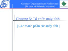
2.4. Mạch tổ hợp
n Mạch logic là mạch bao gồm:
n Các đầu vào (Inputs) n Các đầu ra (Outputs) n Đặc tả chức năng (Functional specification) n Đặc tả thời gian (Timing specification)
n Các kiểu mạch logic:
n Mạch tổ hợp (Combinational Circuits)
n Mạch không nhớ n Đầu ra được xác định bởi các giá trị hiện tại của đầu vào
n Mạch dãy (Sequential Circuits)
cuu duong than cong . co m
n Mạch có nhớ n Đầu ra được xác định bởi các giá trị trước đó và giá trị hiện tại
của đầu vào
2017
Kiến trúc máy tính
71
CuuDuongThanCong.com
https://fb.com/tailieudientucntt
NKK-HUST
Mạch tổ hợp
n Mạch tổ hợp là mạch logic trong đó đầu ra chỉ
phụ thuộc đầu vào ở thời điểm hiện tại
n Là mạch không nhớ và được thực hiện bằng
các cổng logic
n Mạch tổ hợp có thể được định nghĩa theo ba
cách: n Bảng thật (True Table) n Dạng sơ đồ n Phương trình Boole
cuu duong than cong . co m
2017
Kiến trúc máy tính
72
CuuDuongThanCong.com
https://fb.com/tailieudientucntt
11.3 / COMBINATIONAL CIRCUITS 371
Table 11.3 A Boolean Function of Three Variables
A
B
C
F
0
0
0
0
0
0
1
0
0
1
0
1
0
1
1
1
1
0
0
0
1
0
1
0
1
1
0
1
1
1
1
0
There are three combinations of input values that cause F to be 1, and if any
one of these combinations occurs, the result is 1. This form of expression, for self-
evident reasons, is known as the sum of products (SOP) form. Figure 11.4 shows a
straightforward implementation with AND, OR, and NOT gates.
Another form can also be derived from the truth table. The SOP form
expresses that the output is 1 if any of the input combinations that produce 1 is true. We can also say that the output is 1 if none of the input combinations that produce 0 is true. Thus,
NKK-HUST
A B C
A B C
A B C
A B C
A B C
#
#
#
#
F =
This can be rewritten using a generalization of DeMorgan’s theorem: 2
1
1
2
1
1
1
2
Ví dụ
2 2 (X # Y # Z) = X + Y + Z
B
C
A
Đầu vào
Đầu ra
A
B
F
C
F
Figure 11.4 Sum-of-Products Implementation of Table 11.3
0 0 0 0 1 1 1 1
0 0 1 1 0 0 1 1
0 0 1 1 0 0 1 0
0 1 0 1 0 1 0 1
cuu duong than cong . co m
BCACBAF
CAB
+
=
+
2017
Kiến trúc máy tính
73
CuuDuongThanCong.com
https://fb.com/tailieudientucntt
NKK-HUST
Bộ chọn kênh (Multiplexer - MUX)
n 2n đầu vào dữ liệu n n đầu vào chọn n 1 đầu ra dữ liệu n Mỗi tổ hợp đầu vào chọn (S) xác định đầu vào
dữ liệu nào (D) sẽ được nối với đầu ra (F)
cuu duong than cong . co m
2017
Kiến trúc máy tính
74
CuuDuongThanCong.com
https://fb.com/tailieudientucntt
380 CHAPTER 11 / DIGITAL LOGIC
A
B
F
B
C
Figure 11.11 NAND Implementation of
Table 11.3
11.3 / COMBINATIONAL CIRCUITS 381
NAND AND NOR IMPLEMENTATIONS Another consideration in the
Table 11.7 4-to-1 Multiplexer Truth Table
implementation of Boolean functions concerns the types of gates used. It is sometimes
S2
S1
F
desirable to implement a Boolean function solely with NAND gates or solely with
NOR gates. Although this may not be the minimum-gate implementation, it has the
0
0
D0
advantage of regularity, which can simplify the manufacturing process. Consider
0
1
D1
1
0
D2
again Equation (11.3):
1
1
D3
F = B(A + C)
Because the complement of the complement of a value is just the original value,
output signal F. To select one of the four possible inputs, a 2-bit selection code is
F = B(A + C) = (AB + (BC)
needed, and this is implemented as two select lines labeled S1 and S2.
An example 4-to-1 multiplexer is defined by the truth table in Table 11.7. This
Applying DeMorgan’s theorem,
is a simplified form of a truth table. Instead of showing all possible combinations of
input variables, it shows the output as data from line D0, D1, D2, or D3. Figure 11.13
F = (AB)•(BC)
shows an implementation using AND, OR, and NOT gates. S1 and S2 are connected
which has three NAND forms, as illustrated in Figure 11.11.
to the AND gates in such a way that, for any combination of S1 and S2, three of the
Multiplexers
NKK-HUST
AND gates will output 0. The fourth AND gate will output the value of the selected line, which is either 0 or 1. Thus, three of the inputs to the OR gate are always 0, and the output of the OR gate will equal the value of the selected input gate. Using this regular organization, it is easy to construct multiplexers of size 8-to-1, 16-to-1, and so on.
Bộ chọn kênh 4 đầu vào
The multiplexer connects multiple inputs to a single output. At any time, one of the inputs is selected to be passed to the output. A general block diagram representation is shown in Figure 11.12. This represents a 4-to-1 multiplexer. There are four input lines, labeled D0, D1, D2, and D3. One of these lines is selected to provide the
Multiplexers are used in digital circuits to control signal and data routing. An example is the loading of the program counter (PC). The value to be loaded into the program counter may come from one of several different sources:
S2
S1
D0
D1
F
4-to-1 MUX
D2
D0
D3
D1
S2
S1
F
Figure 11.12 4-to-1 Multiplexer Đầu vào chọn Đầu ra Representation
D2
F
S2
S1
D3
cuu duong than cong . co m
Figure 11.13 Multiplexer Implementation
F = D0 • S2 • S1+ D1• S2 • S1+ D2 • S2 • S1+ D3• S2 • S1
0 0 1 1
0 1 0 1
D0 D1 D2 D3
2017
Kiến trúc máy tính
75
CuuDuongThanCong.com
https://fb.com/tailieudientucntt
NKK-HUST
Bộ giải mã (Decoder)
n N đầu vào, 2N đầu ra n Với một tổ hợp của N đầu vào, chỉ có một đầu ra tích cực
(khác với các đầu ra còn lại)
n Ví dụ: Bộ giải mã 2 ra 4
A1
A0
2:4 Decoder
A1 A0
Y3
11 10 01 00
Y3 Y2 Y1 Y0
Y2
cuu duong than cong . co m
Y1
Y0
A1 0 0 1 1
A0 0 1 0 1
Y3 Y2 Y1 Y0 1 0 0 0 0 0 0 1
0 0 1 0
0 1 0 0
2017
Kiến trúc máy tính
76
CuuDuongThanCong.com
https://fb.com/tailieudientucntt
NKK-HUST
Thực hiện bộ giải mã 3 ra 8
11.3 / COMBINATIONAL CIRCUITS 383
A
000
D0
B
001
D1
C
010
D2
011
D3
100
D4
101
D5
cuu duong than cong . co m
110
D6
111
D7
Figure 11.15 Decoder with 3 Inputs and 23 = 8 Outputs
2017
Kiến trúc máy tính
77
CuuDuongThanCong.com
https://fb.com/tailieudientucntt
A0
A7
256 ! 8
256 ! 8
256 ! 8
256 ! 8
RAM
RAM
RAM
RAM
Enable
Enable
Enable
Enable
2-to-4
Decoder
A8
A9
Figure 11.16 Address Decoding
NKK-HUST
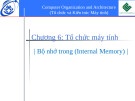
Bộ cộng
n Bộ cộng bán phần 1-bit (Half-adder)
n Cộng hai bit tạo ra bit tổng và bit nhớ ra
n Bộ cộng toàn phần 1-bit (Full-adder)
n Cộng 3 bit n Cho phép xây dựng bộ cộng N-bit
cuu duong than cong . co m
2017
Kiến trúc máy tính
78
CuuDuongThanCong.com
https://fb.com/tailieudientucntt
NKK-HUST
Bộ cộng bán phần 1-bit
A
B
1
0
1
0
+ 0
+ 1
+ 1
+ 0
Cout
1-bit Half Adder
1
1
10
0
S
Đầu ra
Đầu vào
B
S
A
Cout
BA
S
0
0
0
0
AB
C
Å= out =
1
0
1
0
cuu duong than cong . co m
0
1
0
1
1
0
1
1
2017
Kiến trúc máy tính
79
CuuDuongThanCong.com
https://fb.com/tailieudientucntt
NKK-HUST
Bộ cộng toàn phần 1-bit
A
B
Cin
Cout
S = ABC + ABC + ABC + ABC Cout = AB + AC + BC
1-bit Full Adder
11.3 / COMBINATIONAL CIRCUITS 387
S
A B C
Đầu ra
Đầu vào
A B C
S
A
B
S Sum
Cout 0
0
Cin 0
0
0
A B C
1
0
0
0
1
0
1
0
1
0
A B C
1
0
0
1
1
A B
cuu duong than cong . co m
1
0
1
0
0
Carry
0
1
1
0
1
Cout
A C
0
1
1
1
0
B C
1
1
1
1
1
2017
Kiến trúc máy tính
80
Figure 11.20 Implementation of an Adder
CuuDuongThanCong.com
https://fb.com/tailieudientucntt
Thus we have the necessary logic to implement a multiple-bit adder such as
shown in Figure 11.21. Note that because the output from each adder depends on
the carry from the previous adder, there is an increasing delay from the least signifi-
cant to the most significant bit. Each single-bit adder experiences a certain amount
of gate delay, and this gate delay accumulates. For larger adders, the accumulated
delay can become unacceptably high.
If the carry values could be determined without having to ripple through all
the previous stages, then each single-bit adder could function independently, and
delay would not accumulate. This can be achieved with an approach known as carry
lookahead. Let us look again at the 4-bit adder to explain this approach.
We would like to come up with an expression that specifies the carry input to
any stage of the adder without reference to previous carry values. We have
A31
B31
A24 B24
A23
B23
A16 B16
A15
B15
A8 B8
A7
B7
A0 B0
C23
C15
C7
8-bit
8-bit
8-bit
8-bit
Cin
Cout
adder
adder
adder
adder
S31
S24
S23
S16
S15
S8
S7
S0
Figure 11.21 Construction of a 32-Bit Adder Using 8-Bit Adders
386 CHAPTER 11 / DIGITAL LOGIC
Table 11.9 Binary Addition Truth Tables
(b) Addition with Carry Input
(a) Single-Bit Addition
A
Sum
B
Cin
Cout
A
B
Sum
Carry
0
0
0
0
0
0
0
0
0
0
0
1
1
0
0
1
1
0
1
0
1
0
0
1
0
1
0
11.3 / COMBINATIONAL CIRCUITS 387
1
1
0
1
0
1
1
0
1
A
1
0
0
1
0
B
C
1
0
1
0
1
A
1
1
0
0
1
B
1
1
1
1
1
C
Sum
A
B
C
0
0
1
1
A
+0
+1
+0
+1
B
0
1
1
10
C
A
However, addition can still be dealt with in Boolean terms. In Table 11.9a, we
B
show the logic for adding two input bits to produce a 1-bit sum and a carry bit.
This truth table could easily be implemented in digital logic. However, we are not
interested in performing addition on just a single pair of bits. Rather, we wish to
A
Carry
add two n-bit numbers. This can be done by putting together a set of adders so that
C
the carry from one adder is provided as input to the next. A 4-bit adder is depicted
in Figure 11.19.
B
For a multiple-bit adder to work, each of the single-bit adders must have three
C
inputs, including the carry from the next-lower-order adder. The revised truth table
Figure 11.20 Implementation of an Adder
appears in Table 11.9b. The two outputs can be expressed:
Sum = A BC + ABC + ABC + ABC
NKK-HUST
Carry = AB + AC + BC
A3
A2
A1
A0
B1
B0
Thus we have the necessary logic to implement a multiple-bit adder such as Bộ cộng 4-bit và bộ cộng 32-bit shown in Figure 11.21. Note that because the output from each adder depends on Figure 11.20 is an implementation using AND, OR, and NOT gates. the carry from the previous adder, there is an increasing delay from the least signifi- cant to the most significant bit. Each single-bit adder experiences a certain amount of gate delay, and this gate delay accumulates. For larger adders, the accumulated B2 B3 delay can become unacceptably high.
0
Cin
Cin
C1
C0
C3
C2
Cin
Cin
Overflow signal
If the carry values could be determined without having to ripple through all the previous stages, then each single-bit adder could function independently, and delay would not accumulate. This can be achieved with an approach known as carry lookahead. Let us look again at the 4-bit adder to explain this approach.
We would like to come up with an expression that specifies the carry input to
any stage of the adder without reference to previous carry values. We have
S0
S2
S1
S3
Figure 11.19 4-Bit Adder
A16 B16
A8 B8
A23
A15
B23
B15
A31
B31
A24 B24
A7
B7
A0 B0
C23
C15
C7
Cin
Cout
8-bit adder
8-bit adder
8-bit adder
8-bit adder
cuu duong than cong . co m
S31
S24
S23
S16
S15
S8
S7
S0
Figure 11.21 Construction of a 32-Bit Adder Using 8-Bit Adders
2017
Kiến trúc máy tính
81
CuuDuongThanCong.com
https://fb.com/tailieudientucntt
NKK-HUST
2.5. Mạch dãy
n Mạch dãy là mạch logic trong đó đầu ra phụ thuộc giá trị đầu vào ở thời điểm hiện tại và đầu vào ở thời điểm quá khứ
n Là mạch có nhớ, được thực hiện bằng phần tử nhớ (Latch, Flip-Flop) và có thể kết hợp với các cổng logic
cuu duong than cong . co m
2017
Kiến trúc máy tính
82
CuuDuongThanCong.com
https://fb.com/tailieudientucntt
392 CHAPTER 11 / DIGITAL LOGIC
Q
K
Clock
J
Q
Figure 11.26 J–K Flip-Flop
NKK-HUST
causing the output to be 1; if only the K input is asserted, the result is a reset function, causing the output to be 0. When both J and K are 1, the function performed is referred to as the toggle function: the output is reversed. Thus, if Q is 1 and 1 is applied to J and K, then Q becomes 0. The reader should verify that the implementation of Figure 11.26 produces this characteristic function.
Các Flip-Flop cơ bản
Truth Table
Name
Graphical Symbol
S
Q
S
R
Qn!1
Ck
S–R
Qn 0 1 –
0 1 0 1
0 0 1 1
R
Q
Q
J
J
K
Qn!1
Ck
J–K
0 1 0 1
0 0 1 1
Qn 0 1 Qn
K
Q
D
Qn!1
D
Q
cuu duong than cong . co m
Ck
0 1
0 1
D
Q
2017
Kiến trúc máy tính
83
Figure 11.27 Basic Flip-Flops
CuuDuongThanCong.com
https://fb.com/tailieudientucntt
NKK-HUST
S-R Latch và các Flip-Flop
11.4 / SEQUENTIAL CIRCUITS 389
11.4 / SEQUENTIAL CIRCUITS 391
R
Q
R
Q
Clock
11.4 / SEQUENTIAL CIRCUITS 391
R
Q
Q
S
Q
Figure 11.24 Clocked S–R Flip-Flop
S Clock
Figure 11.22 The S–R Latch Implemented with NOR Gates
Q
S-R Flip-Flop
S-R Latch
Q
S
392 CHAPTER 11 / DIGITAL LOGIC
Figure 11.24 Clocked S–R Flip-Flop
Clock
Q
K
Q
Q
First, let us show that the circuit is bistable. Assume that both S and R are 0 and that Q is 0. The inputs to the lower NOR gate are Q = 0 and S = 0. Thus, the output Q = 1 means that the inputs to the upper NOR gate are Q = 1 and R = 0, which has the output Q = 0. Thus, the state of the circuit is internally consistent and remains stable as long as S = R = 0. A similar line of reasoning shows that the state Q = 1, Q = 0 is also stable for R = S = 0.
D
Clock
Figure 11.25 D Flip-Flop
Clock
Q
J
Q
D
cuu duong than cong . co m
Figure 11.25 D Flip-Flop
Figure 11.26 J–K Flip-Flop
Thus, this circuit can function as a 1-bit memory. We can view the output Q as the “value” of the bit. The inputs S and R serve to write the values 1 and 0, respec- tively, into memory. To see this, consider the state Q = 0, Q = 1, S = 0, R = 0. Suppose that S changes to the value 1. Now the inputs to the lower NOR gate are S = 1, Q = 0. After some time delay ^t, the output of the lower NOR gate will be Q = 0 (see Figure 11.23). So, at this point in time, the inputs to the upper NOR gate become R = 0, Q = 0. After another gate delay of ^t the output Q becomes 1. This is again a stable state. The inputs to the lower gate are now S = 1, Q = 1, which maintain the output Q = 0. As long as S = 1 and R = 0, the outputs will remain Q = 1, Q = 0. Furthermore, if S returns to 0, the outputs will remain unchanged.
D Flip Flop
J-K Flip-Flop
Kiến trúc máy tính
arrangement. This device is referred to as a clocked S–R flip-flop. Note that the R and S inputs are passed to the NOR gates only during the clock pulse. D FLIP-FLOP One problem with S–R flip-flop is that the condition R = 1, S = 1 must be avoided. One way to do this is to allow just a single input. The D flip-flop accomplishes this. Figure 11.25 shows a gate implementation of the D flip-flop. By using an inverter, the nonclock inputs to the two AND gates are guaranteed to be the opposite of each other. causing the output to be 1; if only the K input is asserted, the result is a reset function, The D flip-flop is sometimes referred to as the data flip-flop because it is, in causing the output to be 0. When both J and K are 1, the function performed is effect, storage for one bit of data. The output of the D flip-flop is always equal to the referred to as the toggle function: the output is reversed. Thus, if Q is 1 and 1 is applied most recent value applied to the input. Hence, it remembers and produces the last to J and K, then Q becomes 0. The reader should verify that the implementation of input. It is also referred to as the delay flip-flop, because it delays a 0 or 1 applied to 84 Figure 11.26 produces this characteristic function. its input for a single clock pulse. We can capture the logic of the D flip-flop in the following truth table:
CuuDuongThanCong.com
https://fb.com/tailieudientucntt
D Qn ! 1
The D flip-flop is sometimes referred to as the data flip-flop because it is, in effect, storage for one bit of data. The output of the D flip-flop is always equal to the most recent value applied to the input. Hence, it remembers and produces the last
arrangement. This device is referred to as a clocked S–R flip-flop. Note that the R and S inputs are passed to the NOR gates only during the clock pulse. The R output performs the opposite function. When R goes to 1, it forces D FLIP-FLOP One problem with S–R flip-flop is that the condition R = 1, S = 1 Q = 0, Q = 1 regardless of the previous state of Q and Q. Again, a time delay of must be avoided. One way to do this is to allow just a single input. The D flip-flop 2^t occurs before the final state is established (Figure 11.23). accomplishes this. Figure 11.25 shows a gate implementation of the D flip-flop. By The S–R latch can be defined with a table similar to a truth table, called a using an inverter, the nonclock inputs to the two AND gates are guaranteed to be characteristic table, which shows the next state or states of a sequential circuit as 2017 the opposite of each other. a function of current states and inputs. In the case of the S–R latch, the state can be defined by the value of Q. Table 11.10a shows the resulting characteristic table. Observe that the inputs S = 1, R = 1 are not allowed, because these would pro- duce an inconsistent output (both Q and Q equal 0). The table can be expressed
Name
Graphical Symbol
Truth Table
input. It is also referred to as the delay flip-flop, because it delays a 0 or 1 applied to
0
0
more compactly, as in Table 11.10b. An illustration of the behavior of the S–R latch
its input for a single clock pulse. We can capture the logic of the D flip-flop in the
1
1
is shown in Table 11.10c.
following truth table:
Q
S
S
R
Qn!1
CLOCKED S–R FLIP-FLOP The output of the S–R latch changes, after a brief
J–K FLIP-FLOP Another useful flip-flop is the J–K flip-flop. Like the S–R flip-flop,
D Qn ! 1
time delay, in response to a change in the input. This is referred to as asynchronous
0
0
Qn
it has two inputs. However, in this case all possible combinations of input values are
operation. More typically, events in the digital computer are synchronized to a clock
Ck
0
0
S–R
0
1
0
valid. Figure 11.26 shows a gate implementation of the J–K flip-flop, and Figure 11.27
pulse, so that changes occur only when a clock pulse occurs. Figure 11.24 shows this
1
1
0
1
1
shows its characteristic table (along with those for the S–R and D flip-flops). Note
–
1
1
R
Q
that the first three combinations are the same as for the S–R flip-flop. With no input
J–K FLIP-FLOP Another useful flip-flop is the J–K flip-flop. Like the S–R flip-flop,
asserted, the output is stable. If only the J input is asserted, the result is a set function,
it has two inputs. However, in this case all possible combinations of input values are
valid. Figure 11.26 shows a gate implementation of the J–K flip-flop, and Figure 11.27
J
Q
J
K
Qn!1
shows its characteristic table (along with those for the S–R and D flip-flops). Note
0
0
Qn
that the first three combinations are the same as for the S–R flip-flop. With no input
Ck
J–K
0
1
0
asserted, the output is stable. If only the J input is asserted, the result is a set function,
1
1
0
1
1
Qn
K
Q
D
Qn!1
D
Q
0
0
Ck
1
1
D
Q
Figure 11.27 Basic Flip-Flops
NKK-HUST
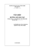
Thanh ghi 8-bit song song
11.4 / SEQUENTIAL CIRCUITS 393
Data lines
D18
D12
D11
D17
D13
D14
D15
D16
D
Q
D
D
Q
Q
Q
Q
D
D
D
Q
D
Q
D
Q
Clk
Clk
Clk
Clk
Clk
Clk
Clk
Clk
Clock Load
D08
D07
D06
D05
D04
D03
D02
D01
Output lines
Figure 11.28 8-Bit Parallel Register
cuu duong than cong . co m
Registers
As an example of the use of flip-flops, let us first examine one of the essential ele- ments of the CPU: the register. As we know, a register is a digital circuit used within the CPU to store one or more bits of data. Two basic types of registers are com- monly used: parallel registers and shift registers.
Kiến trúc máy tính
85
2017
https://fb.com/tailieudientucntt
CuuDuongThanCong.com
PARALLEL REGISTERS A parallel register consists of a set of 1-bit memories that can be read or written simultaneously. It is used to store data. The registers that we
have discussed throughout this book are parallel registers.
The 8-bit register of Figure 11.28 illustrates the operation of a parallel register
using D flip-flops. A control signal, labeled load, controls writing into the register
from signal lines, D11 through D18. These lines might be the output of multiplexers,
so that data from a variety of sources can be loaded into the register.
SHIFT REGISTER A shift register accepts and/or transfers information serially.
Consider, for example, Figure 11.29, which shows a 5-bit shift register constructed
from clocked D flip-flops. Data are input only to the leftmost flip-flop. With each
clock pulse, data are shifted to the right one position, and the rightmost bit is
transferred out.
Shift registers can be used to interface to serial I/O devices. In addition, they
can be used within the ALU to perform logical shift and rotate functions. In this
D
Q
D
Q
D
Q
D
Q
D
Q
Serial in
Serial out
Clk
Clk
Clk
Clk
Clk
Clock
Figure 11.29 5-Bit Shift Register
11.4 / SEQUENTIAL CIRCUITS 393
Data lines
D18
D17
D16
D15
D14
D13
D12
D11
D
Q
D
Q
D
Q
D
Q
D
Q
D
Q
D
Q
D
Q
Clk
Clk
Clk
Clk
Clk
Clk
Clk
Clk
Clock
Load
D08
D07
D06
D05
D04
D03
D02
D01
Output lines
Figure 11.28 8-Bit Parallel Register
Registers
As an example of the use of flip-flops, let us first examine one of the essential ele-
ments of the CPU: the register. As we know, a register is a digital circuit used within
the CPU to store one or more bits of data. Two basic types of registers are com-
monly used: parallel registers and shift registers.
PARALLEL REGISTERS A parallel register consists of a set of 1-bit memories that
can be read or written simultaneously. It is used to store data. The registers that we
have discussed throughout this book are parallel registers.
The 8-bit register of Figure 11.28 illustrates the operation of a parallel register
using D flip-flops. A control signal, labeled load, controls writing into the register
from signal lines, D11 through D18. These lines might be the output of multiplexers,
so that data from a variety of sources can be loaded into the register.
NKK-HUST
Thanh ghi dịch 5-bit
SHIFT REGISTER A shift register accepts and/or transfers information serially. Consider, for example, Figure 11.29, which shows a 5-bit shift register constructed from clocked D flip-flops. Data are input only to the leftmost flip-flop. With each clock pulse, data are shifted to the right one position, and the rightmost bit is transferred out.
Shift registers can be used to interface to serial I/O devices. In addition, they can be used within the ALU to perform logical shift and rotate functions. In this
D
Q
D
Q
D
D
D
Q
Q
Q
Serial in
Serial out
Clk
Clk
Clk
Clk
Clk
Clock
Figure 11.29 5-Bit Shift Register
cuu duong than cong . co m
2017
Kiến trúc máy tính
86
CuuDuongThanCong.com
https://fb.com/tailieudientucntt
394 CHAPTER 11 / DIGITAL LOGIC
latter capacity, they need to be equipped with parallel read/write circuitry as well
as serial.
Counters
Another useful category of sequential circuit is the counter. A counter is a register
whose value is easily incremented by 1 modulo the capacity of the register; that is,
after the maximum value is achieved the next increment sets the counter value to 0.
Thus, a register made up of n flip-flops can count up to 2n - 1. An example of a
counter in the CPU is the program counter.
Counters can be designated as asynchronous or synchronous, depending on
the way in which they operate. Asynchronous counters are relatively slow because
the output of one flip-flop triggers a change in the status of the next flip-flop. In a
synchronous counter, all of the flip-flops change state at the same time. Because the
latter type is much faster, it is the kind used in CPUs. However, it is useful to begin
the discussion with a description of an asynchronous counter.
RIPPLE COUNTER An asynchronous counter is also referred to as a ripple counter,
NKK-HUST
because the change that occurs to increment the counter starts at one end and “ripples” through to the other end. Figure 11.30 shows an implementation of a 4-bit counter using J–K flip-flops, together with a timing diagram that illustrates its behavior. The timing diagram is idealized in that it does not show the propagation delay that occurs as the signals move down the series of flip-flops. The output of Bộ đếm 4-bit the leftmost flip-flop (Q0) is the least significant bit. The design could clearly be extended to an arbitrary number of bits by cascading more flip-flops.
High
J
Q
J
J
J
Q
Q
Q
Ck
Ck
Ck
Ck
Clock
Q
Q
Q
Q
K
K
K
K
Q2
Q3
Q0
Q1
(a) Sequential circuit
Clock
Q0
Q1
Q2
cuu duong than cong . co m
Q3
(b) Timing diagram
Figure 11.30 Ripple Counter
2017
Kiến trúc máy tính
87
CuuDuongThanCong.com
https://fb.com/tailieudientucntt
NKK-HUST
Hết chương 2
cuu duong than cong . co m
2017
Kiến trúc máy tính
88
CuuDuongThanCong.com
https://fb.com/tailieudientucntt