
Hindawi Publishing Corporation
EURASIP Journal on Advances in Signal Processing
Volume 2008, Article ID 352796, 12 pages
doi:10.1155/2008/352796
Research Article
Link-Adaptive Distributed Coding for Multisource Cooperation
Alfonso Cano, Tairan Wang, Alejandro Ribeiro, and Georgios B. Giannakis
Department of Electrical and Computer Engineering, University of Minnesota, 200 Union Street, Minneapolis, MN 55455, USA
Correspondence should be addressed to Georgios B. Giannakis, georgios@umn.edu
Received 14 May 2007; Accepted 7 September 2007
Recommended by Keith Q. T. Zhang
Combining multisource cooperation and link-adaptive regenerative techniques, a novel protocol is developed capable of achieving
diversity order up to the number of cooperating users and large coding gains. The approach relies on a two-phase protocol.
In Phase 1, cooperating sources exchange information-bearing blocks, while in Phase 2, they transmit reencoded versions of
the original blocks. Different from existing approaches, participation in the second phase does not require correct decoding of
Phase 1 packets. This allows relaying of soft information to the destination, thus increasing coding gains while retaining diversity
properties. For any reencoding function the diversity order is expressed as a function of the rank properties of the distributed
coding strategy employed. This result is analogous to the diversity properties of colocated multi-antenna systems. Particular cases
include repetition coding, distributed complex field coding (DCFC), distributed space-time coding, and distributed error-control
coding. Rate, diversity, complexity, and synchronization issues are elaborated. DCFC emerges as an attractive choice because
it offers high-rate, full spatial diversity, and relaxed synchronization requirements. Simulations confirm analytically established
assessments.
Copyright © 2008 Alfonso Cano et al. This is an open access article distributed under the Creative Commons Attribution License,
which permits unrestricted use, distribution, and reproduction in any medium, provided the original work is properly cited.
1. INTRODUCTION
In distributed virtual antenna arrays (VAA) enabled by user
cooperation, there is a distinction as to how users decide
to become part of the VAA for a given transmitted packet.
Most relaying techniques can be classified either as analog
forwarding (AF), decode-and-forward (DF), and selective
forwarding (SF) [1–3]. In SF, prospective cooperators de-
code each source packet and, if correctly decoded, they co-
operate by relaying a possibly reencoded signal. In AF, co-
operating terminals amplify the received (transmitted signal
plus noise) waveform. Both strategies achieve full diversity
equal to the number of users forming the VAA, and in some
sense their advantages and drawbacks are complementary.
One of the major limitations of AF is that it requires storage
of the analog-amplitude received waveform, which strains
resources at relaying terminals, whereas SF implementation
is definitely simpler. However, relaying information in SF is
necessarily done on a per-packet basis eventually leading to
the dismissal of an entire packet because of a small num-
ber of erroneously decoded symbols. This drawback is some-
times obscured in analyses because it does not affect the di-
versity gain of the VAA. It does affect the coding gain, though,
and in many situations, SF does not improve performance of
noncooperative transmissions because the diversity advan-
tage requires too high signal-to-noise ratios (SNR) to “kick-
in” in practice [4].
Simple implementation with high diversity and coding
gains is possible with the DF-based link-adaptive regenera-
tive (LAR) cooperation, whereby cooperators repeat packets
based on the instantaneous SNR of the received signal [4]. In
LAR cooperation, relays retransmit soft estimates of received
symbols with power proportional to the instantaneous SNR
in the source-to-relay link—available through, for example,
training—but never exceeding a given function of the aver-
age SNR in the relay-to-destination link which is available
through, for example, low-rate feedback. With LAR-based
cooperation, it suffices to perform maximum-ratio combin-
ing (MRC) at the destination to achieve full diversity equal to
the number of cooperators [4]. Finally, link-adaptive cooper-
ation was also considered for power-allocation purposes, as
in [5,6], and references therein.
In the present paper, we extend LAR cooperation to gen-
eral distributed coding strategies operating over either or-
thogonal or nonorthogonal channels. For that matter, we
consider a multisource cooperation (MSC) setup, whereby
a group of users collaborate in conveying information sym-
bols to a common destination [7,8]. In Phase 1, terminals

2 EURASIP Journal on Advances in Signal Processing
sequentially transmit their information bearing signals. Due
to the broadcast nature of wireless transmissions, signals are
overheard by other terminals that use these received wave-
forms to estimate the information sent by other sources. In
Phase 2, sources (re)encode the aggregate information packet
that they then transmit to the destination. Combining the
signals received during both phases, the destination estimates
the sources data. The goal of this paper is to analyze the di-
versity of LAR-MSC protocols in terms of general properties
of the reencoding function used during Phase 2. Particular
cases of reencoding functions include (LAR based) (i) repe-
tition coding, (ii) distributed complex field coding (DCFC),
(iii) distributed space-time (ST) coding, and (iv) distributed
error control coding (DECC).
The use of coding techniques (i)–(iv) in SF relaying has
been considered in, for example, [8–12], where different di-
versity properties are reported. The use of repetition coding
as in (i) with average SNR source-relay knowledge at the re-
ceivers was tackled in [9] using a piecewise linear (PL) de-
tector that established diversity bounds. Alamouti codes [13]
were considered as in (iii) with regenerative relays in [10,11].
In particular, full diversity was demonstrated in [11] if the
per-fading error probability of the relay can become avail-
able at the destination. DCFC and DECC cooperation in a
multiple access channel, using a 2-phase protocol similar to
the one proposed here in (ii) and (iv), was advocated by
[8,12], respectively. Assuming that to participate in the Phase
2, sources have to correctly decode the packets of all other
peers, diversity order as high as the number of cooperating
terminals was established.
In general terms, the present work differs from exist-
ing alternatives in that LAR cooperation is employed to
enable high error performance (in coding gain and diver-
sity) even if packets are not correctly decoded and realis-
tic channel knowledge is available at terminals and desti-
nation. Our main result is to show that the diversity or-
der of LAR-MSC coincides with that of a real antenna ar-
ray using the same encoding function used by the VAA cre-
ated by MSC. In particular, this establishes that for a net-
work with Nusers, the diversity orders are (i) 2 for repe-
tition coding, (ii) Nfor DCFC, (iii) at least the same di-
versity order afforded by the ST code in a conventional an-
tenna array when we use distributed ST coding, and (iv) for
DECC, the same diversity achieved by the ECC over an N-lag
block fading channel. Through simulations we also corrobo-
rate that, having the same diversity gain, LAR transmissions
enable higher coding gains than those afforded by SF-based
transmissions.
The rest of the paper is organized as follows. In Section 2,
we introduce the 2-phase LAR-MSC protocol. We define a
generic encoding function and specialize it to repetition cod-
ing and DCFC. We then move on to Section 3 where we
present the main result of the paper characterizing the diver-
sity gain in terms of the properties of the distributed coder.
We discuss the application of our result to repetition coding,
DCFC, distributed ST coding, and DECC in Section 3.2.In
this section, we also compare these four different strategies
in terms of diversity, decoding complexity, synchronization,
and bandwidth efficiency. Section 3.1 is devoted to prove the
main result introduced in Section 3. We present corroborat-
ing simulations in Section 4.
Notation 1. Upper (lower) bold face letters will be used for
matrices (column vectors); [·]i,j([·]i) for the i,jth (ith) en-
try of a matrix (vector); [·]i,: ([·]:, j) for the ith ( jth) row
(column) of a matrix; [·]i:jwill denote a vector formed ex-
tracting elements from ito j;INthe N×Nidentity matrix;
1Nthe N×1 all-one vector; ⊗the Kroneker product; · the
Frobenius norm; R∪S(R∩S) the union (intersection) of
sets Rand S;|S|the cardinality of a set S;∅the empty set;
and CN (µ,σ2) will stand for a complex Gaussian distribu-
tion with mean µand variance σ2.
2. LINK-ADAPTIVE REGENERATIVE
MULTI-SOURCE COOPERATION
Consider a set of sources {Sn}N
n=1communicating with a
common access point or destination SN+1. Information bits
of Snare modulated and parsed into K×1 blocks of symbols
xn:=[xn1,...,xnK ]Twith xnk drawn from a finite alpha-
bet (constellation) As. Terminals cooperate in accordance
to a two-phase protocol. In Phase 1, sources {Sn}N
n=1trans-
mit their symbols to the destination SN+1 in nonoverlapping
time slots. Thanks to broadcast propagation, symbols trans-
mitted by Snare also received by the other N−1sources
{Sm}N
m=1,m/
=n; see also Figure 1.Lety(m)
nrepresent the K×1
block received at Sm,m∈[1, N+1],m/
=nfrom Sn,n∈
[1, N]. The Sn→Smlink is modeled as a block Rayleigh fad-
ing channel with coefficients h(m)
n∼CN (0, (σ(m)
n)2γ). Defin-
ing normalized additive white Gaussian noise (AWGN) terms
w(m)
n∼CN (0, IK) for the Sn→Smlink, we can write the
Phase-1 input-output relations as
y(m)
n=h(m)
nxn+w(m)
n,m∈[1, N+1],n∈[1, N], n/
=m,
(1)
where we recall m=N+ 1 denotes the signal received at
the common destination SN+1. For reference, we also define
the instantaneous output SNR of each link γ(m)
n:=|h(m)
n|2
and the corresponding average SNR as γ(m)
n=(σ(m)
n)2γ[cf.
h(m)
n∼CN (0, (σ(m)
n)2γ)].
After Phase 1, each source has available an estimate of
the other sources blocks. Let x(m)
ndenote the estimate of the
source block xnformed at source Sm,m∈[1, N], m/
=n.Due
to communication errors, x(m)
nwill generally differ from the
original block xnand from estimates x(l)
nat different sources
Sl/
=Sm.
In Phase 2, each source transmits to the destination a
block that contains coded information from other sources’
blocks. To be precise, consider the set of Phase-1 transmitted
blocks, :={xn}N
n=1.Ifxwere perfectly known at Sm,itwould
have been possible to form a reencoded block vmof size L×1
obtained from xthrough a mapping Mm, that is,
vm=Mm(x).(2)
Note, however, that xis not necessarily known at Sm.Infact,
source Smcollects all estimates {x(m)
n}N
n=1,n/
=mplus its own
Alfonso Cano et al. 3
S1
Sm
SN
SN+1
.
.
.
x1
xN
xm
vm
γ(m)
1
γ(m)
N
γ(N+1)
m
αmγ(N+1)
m
αm:=min{minm/
=n{γ(m)
n},γ(N+1)
m}
γ(N+1)
m
Phase-1
Phase-2
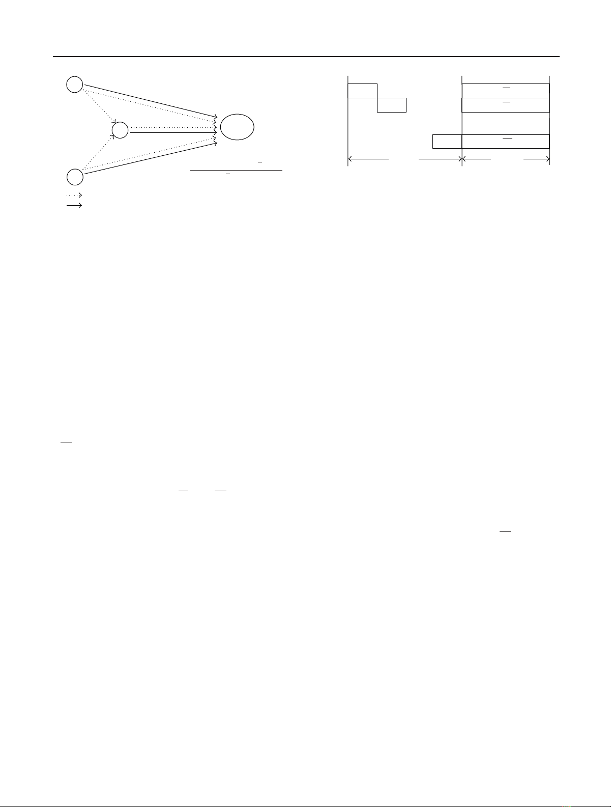
Figure 1: Transmitted and received signals at Smduring Phase 1 and
Phase 2.
information xmin the set x(m):={xm,{x(m)
n}N
n=1,n/
=m}.The
L×1vectorvmbuilt by Smin Phase 2 is thus obtained from
x(m)as
vm=Mmx(m).(3)
Comparing (2)with(3) we see that different from the MSC
strategies in [7,14], we are encoding based on a set of error-
corrupted blocks x(m). To make this explicit, we denoted the
mapped block as vm[cf. (3)] to emphasize that it may be dif-
ferent from the desired vm[cf. (2)].
Propagation of decoding errors can have a detrimental ef-
fect on error performance at the destination. To mitigate this
problem, our approach is to have source Smadjust its Phase-
2 transmitted power using a channel-adaptive scaling coef-
ficient αm. The block transmitted from Smin Phase 2 is thus
√αmvm. The signal y(N+1,2) received at the destination SN+1 is
the superposition of the Nsource signals; see Figure 2.Upon
defining a matrix of transmitted blocks
V:=[v1,...,vN]=
[M1(x(1)), ...,MN(x(N))], a diagonal matrix containing the
αmcoefficients Dα:=diag([√α1,...,√αN]) and the aggre-
gate channel h(N+1) :=[h(N+1)
1,...,h(N+1)
N]Tcontaining the
coefficients from all sources to the destination, we can write
y(N+1,2) =
VDαh(N+1) +w(N+1,2).(4)
The destination estimates the set of transmitted blocks xus-
ing the Nblocks of Ksymbols y(N+1,1)
nreceived during Phase
1 and the Lsymbols y(N+1,2) received during Phase 2. As-
suming knowledge of the product Dαh(N+1) (through, e.g.,
a training phase), demodulation at the destination relies on
the detection rule
x=arg min
x∈AKN
sN
n=1
y(N+1,1)
n−diagxnh(N+1)
2
+
y(N+1,2) −VDαh(N+1)
2,
(5)
where V:=[v1,...,vN]=[M1(x), ...,MN(x)]. The search
in (5) is performed over the set of constellation codewords
xwith size |As|KN. Note that this is a general detector for
performance analysis purposes but its complexity does not
necessarily depend on the size of the set x; see also Section 4.
Phase 1 Phase 2
x1
x2
...
xN
h(N+1)
1
h(N+1)
2
h(N+1)
N
√α1v1
√α2v2
.
.
.
√αNvN
Figure 2: Time-division scheduling for Nsources during Phase 1
and simultaneous transmissions during Phase 2.
The goal of this paper is to characterize the diversity of
the 2-phase MSC protocol with input/output relations (1)
and (4) and detection rule (5) in terms of suitable proper-
ties of the mappings Mm. In particular, we will show that
for given mappings Mm, an appropiate selection of the co-
efficients Dαenables diversity order equal to an equivalent
multi-antenna system with Ncolocated transmit antennas;
that is, when no inter-source error occurs. Purposefully gen-
eral, to illustrate notation, let us describe two examples for
Mmyielding different MSC protocols.
Example 1 (repetition coding). A simple cooperation strat-
egy for Phase 2 is that each source retransmits the packet of
one neighbor; that is, if we build a mapping
Mm:vm=0T
(m−1)P,xT
m,0T
(N−m)PT(6)
with m=mod[m,N]+1, the mth terminal repeats the m−1)st
signal’s estimate for m/
=1 and the first terminal repeats the
Nth signal’s estimate. Note that the all-zero vectors appended
before and after xT
mare to separate transmissions in time dur-
ing Phase 2. With this definition, it can be seen that the opti-
mum receiver in (5) simplifies for each entry kto
[x(N+1)
m]k=arg min
x∈As
y(N+1,1)
mk−h(N+1)
mx
2
+
y(N+1,2)
(m+1)K+k−√αmh(N+1)
mx
2
.
(7)
Example 2 (distributed complex-field coding). Define the
N×1columnvectorp(m)
k:=[[x(m)
1]k,...,[xm]k,...,[x(m)
N]k]T
and linearly code it using a row 1 ×Nvector θT
m, taken as the
mth row of a complex-field coding matrix Θ[15]. Repeating
this process for all k, the mapping Mmnow becomes
Mm:vm=0T
(m−1)P,θT
mp(m)
1,...,p(m)
K,0T
(N−m)PT.(8)
In this case, the destination SN+1 can decode p(m)
kusing the
following detection rule:
p(N+1)
k=arg min
pk∈AN
s
q(N+1,1)
k−diag(pk)h(N+1)
2
+
q(N+1,2)
k−diag(Θpk)Dαh(N+1)
2,
(9)

4 EURASIP Journal on Advances in Signal Processing
where q(N+1,1)
k:=[[y(N+1,1)
1]k,...,[y(N+1,1)
N]k]Tand q(N+1,2)
k:=
[[y(N+1,2)](k−1)N+1,...,[y(N+1,2)
N]kN ]T.
3. ERROR-PROBABILITY ANALYSIS
The purpose of this section is to determine the high-SNR di-
versity order of MSC protocols in terms of suitable properties
of the mapping Mm. For given channels H(d):={h(N+1)
n}N
n=1
from sources to destination and H(s):={h(m)
n}N
m,n=1,m/
=nbe-
tween sources, we define the so-called conditional (or in-
stantaneous) pairwise error probability (PEP) Pr {x/
=x|
H(s),H(d)}as the probability of decoding xwhen xwas
transmitted and denoted as Pr {x→x|H(s),H(d)}.The
diversity order of the MSC protocol is defined as the slope of
the logarithm of the average PEP as the SNR goes to infinity,
that is,
d=min
x,x/
=x−lim
γ→∞
log EPr x−→ x|H(s),H(d)
log γ.(10)
For MIMO block-fading channels, the diversity order d
depends on the rank distance between constellation code-
words [16]. This will turn out to be generalizable to the VAA
created in LAR-MSC systems. For that matter, define the set
X:=n|xn−xn/
=0(11)
containing the indices of the sources transmitting different
packets. For the same xand xconsider the corresponding
phase-2 blocks Vand
V. We are interested in a subset of
columns of (V−
V) that form a basis of the span of its
columns. This can be formally defined as
V:=n|spanvn−vnn∈V=span(V−
V),(12)
where span(·) denotes the span of a set of vectors or columns
of a matrix. With reference to Figure 2, if we assume
V=V,
the equivalent system can be seen as a MISO block-faded
transmission and the achievable diversity order is related to
rank (V−
V)=|V|over all possible pairs, where rank(·)
denotes the rank of a matrix. We are now challenged to es-
tablish similar diversity claims when
V/
=Valong with the
contribution to diversity of Xafter Phase 1. The pertinent
result is summarized in the following theorem we prove in
Section 3.1.
Theorem 1. Consider two distinct blocks x,xand the pairwise-
error indicator sets Xand Vdefined in (11)and (12),respec-
tively. Let the Phase-2 power-weighting coefficients {αn}N
n=1be
αm:=min min m/
=nγ(m)
n,γ(N+1)
m
γ(N+1)
m
, (13)
where γ(m)
nγ(N+1)
mis the instantaneous (average) SNR of link
Sn−Sm(Sm−SN+1), m∈[1, N]. The average diversity order
as defined in (10)of the MSC protocol defined in (1)–(5)is
d=min
x,x/
=x−lim
γ→∞
log Pr{x−→ x}
log γ=min
x,x/
=x|X∪V|.
(14)
The coefficient αmin (13) is formed based on the instan-
taneous SNR of the links through which blocks {y(m)
n}N
n=1,n/
=m
arrived (available, e.g., by appending a training sequence)
and the average SNR of its link to the destination, which is
assumed to slowly fade at long scale, and thus is feasible to
be fed back. These same conventions have also been adopted
in the context of DF protocols in [4,9]. In [9], the average
channel is assumed to be known for decoding at the desti-
nation, whereas in [4] average knowledge is assumed to be
known at the relays; the latter has been proved to be full-
diversity achieving, while the former cannot achieve full-
diversity, which in our set-up amounts to N, the number of
sources transmitting to the destination.
As detailed in the next subsection, the diversity order can
be assessed by establishing proper bounds on the PEP as in,
for example, [9]or[4]. However, for systems with the same
diversity order, comparing relative performance typically re-
lies on their respective coding gains [17, Chapter 2]. Unfor-
tunately, analytical assessment of coding gains is rarely pos-
sible in closed form especially for the DF-based cooperative
systems even for simple constellations using repetition cod-
ing; see also [9] for similar comments. For this reason, we
will resort to simulated tests in order to assess coding-gain
performance in Section 4.
3.1. Proof of Theorem 1
The difficulty in proving Theorem 1 is the possibility of hav-
ing decoding errors between cooperating terminals, that is,
x(m)/
=x. Thus, define the set of sources’ indices that estimate
xerroneously,
E:=m|x/
=x(m).(15)
By definition E’s complement Econtains the indices of the
sources that decoded xcorrectly. For a given set Eof correct
decoders, one expects that sources {Sm}m∈Ehelp to increase
the detection probability, whereas sources {Sm}m∈Etend to
decrease it.
In terms of diversity, not all of the elements of Econ-
tribute to increasing its order. In fact, for Smto contribute to
the diversity order it also has to belong to the set (X∪V).
Thus, we define the set
C:=(X∪V)∩E.(16)
The cardinality of Ccan be bounded as |C|≥|X∪V|−|E|.
Note also that C∩E=∅.
Using these definitions, we can condition on the set of
correct decoders Eand bound (i) the probability Pr {x→
{x(m)}N
m=1|H(s)}of erroneous detection at the sources af-
ter Phase 1; and (ii) the probability Pr {x,{x(m)}N
m=1→x|
H(s),H(d)}of incorrect detection at the destination after
Phase 1 and Phase 2. The result is stated in the following
lemma.
Lemma 1. Consider a transmitted block x,asetofestimated
blocks {x(m)}N
m=1at terminals {Sm}N
m=1, and an estimated block
xat the destination. Let (i) Eand Cdenote the sets defined in

Alfonso Cano et al. 5
(15)and (16);(ii) let γ(m)
n=|h(m)
n|2and γ(N+1)
n=|h(N+1)
n|2
be the instantaneous SNRs in the Sn→Smand Sn→SN+1
links; and (iii) let αmdenote the power scaling constant in (13).
Conditioned on fading realizations,
(a) the conditional probability of decoding {x(m)}N
m=1at
{Sm}N
m=1given that xwas transmitted in Phase-1 can be
bounded as
Pr x−→ x(m)N
m=1|H(s)≤κ1exp −κ2
n∈E
min
m/
=nγ(m)
n
(17)
for some finite constants κ1,κ2;
(b) the conditional probability of detecting xgiven that
xwas transmitted in Phase-1 and {x(m)}N
m=1in Phase-2 is
bounded as
Pr x,x(m)N
m=1−→ x|H(s),H(d)
≤Q⎛
⎝κ3n∈Cαnγ(N+1)
n−κ4n∈Eαnγ(N+1)
n
κ3n∈Cαnγ(N+1)
n+κ4n∈Eαnγ(N+1)
n⎞
⎠(18)
for some finite constants κ3,κ4.
Proof. See Appendices Aand B.
Using results (a) and (b) of Lemma 1, we can bound the
PEP in (10)toobtain
Pr x−→ x|H(s),H(d)
≤
∀{x(m)}N
m=1
κ1exp −κ2
n∈E
min
m/
=nγ(s)
m,n
×Q⎛
⎝κ3n∈Cαnγ(N+1)
n−κ4n∈Eαnγ(N+1)
n
κ3n∈Cαnγ(N+1)
n+κ4n∈Eαnγ(N+1)
n⎞
⎠.
(19)
To interpret the bound in (19) let us note that the factors
in (17)and(18) are reminiscent of similar expressions that
appear in error-probability analysis of fading channels [18,
Chapter 14]. Taking expected values over the complex Gaus-
sian distribution of the channels in H(s)and H(d)allows us
to bound the right-hand side of (17)as
Eexp −κ2
n∈E
min
m/
=nγ(m)
n≤k1γ−|E|(20)
for some constant k1.Withrespectto(
18), we expect de-
coding errors at Snwhen some of the fading coefficients
{γ(m)
n}m/
=nare small. In turn, since αn≤min m/
=n{γ(m)
n}we
expect n∈Eαnγ(N+1)
nto be small since n∈Ewhen decoding
errors are present at Sn. Thus, the right-hand side of (18)can
be approximated as
Q⎛
⎝κ3n∈Cαnγ(N+1)
n−κ4n∈Eαnγ(N+1)
n
κ3n∈Cαnγ(N+1)
n+κ4n∈Eαnγ(N+1)
n⎞
⎠
≈Qκ3
n∈C
αnγ(N+1)
n.
(21)
As is well known [18, Chpater 14], the expected value of the
right-hand side of (21) can be bounded as
EQκ3
n∈C
αnγ(N+1)
n≤k2γ−|C|(22)
for some constant k2.
Combining (22), (20), and (19), we could deduce that
Pr {x→x}:=E[Pr {x→x|H(s),H(d)}]≤(k1k2γ)−|C|−|E|.
Since |C|≥|X∪V|−|E|,wehave|C|+|E|≥|X∪V|,
which establishes Theorem 1.Thisargumentisnotaproof
however, since (22) is a bound on the approximation (21).
Furthermore, the factors in the products of (19)aredepen-
dent through αm:=min {min m/
=n{γ(m)
n},γ(N+1)
m}/γ(N+1)
m[cf.
(13)] and cannot be factored into a product of expectations.
The next lemma helps us to overcome these technical diffi-
culties.
Lemma 2. For some error probability P′
e{γc,γe,ηc,ηe}satisfy-
ing
P′
eγc,γe,ηc,ηe≤κ1exp −κ2γeQκ3γcηc−κ4γeηe
κ3 γcηc+κ4γeηe
(23)
for some finite constants κ1,κ2,κ3,κ4,andγc∼Gamma (|C|,
1/γ),γe∼Gamma (|E|,1/γ);γc,ηc,γe,andηeare nonneg-
ative and independent of each other, if the probability density
functions p(ηc)and p(ηe)do not depend on γ, the expectation
over γc,γe,ηc,andηeis bounded as
P′
e≤(kγ)−|C|−|E|(24)
with k:=E[k(ηc,ηe)] a constant not dependent on γ.
Proof. See [19].
Combining Lemmas 1and 2,wecanproveTheorem 1 as
we show next.
Proof of Theorem 1.Using the definition of αmin (13), one
can derive the following bounds on the probability expressed
in (19):
n∈E
αnγ(N+1)
n=
n∈E
min min mγ(m)
n,γ
γγ(N+1)
n
≤
n∈E
min
mγ(m)
nn∈Eγ(N+1)
n
γ,
n∈C
αnγ(N+1)
n=
n∈C
γ(N+1)
n
×
n∈C
min min mγ(m)
n,γ
γ
γ(N+1)
n
n∈Cγ(N+1)
n
≥
n∈C
γ(N+1)
nmin min ∀m,n∈Cγ(m)
n,γ
γ,
(25)
where we set all instantaneous SNRs to have the same average
γ; that is, one can pick the maximum average SNR among all


![Đồ án tốt nghiệp: Phân tích và thiết kế mạng [Chuẩn SEO]](https://cdn.tailieu.vn/images/document/thumbnail/2025/20250912/maithanhtam2008/135x160/90431757666930.jpg)

![Website bán điện thoại di động: Đồ án tốt nghiệp [Chuẩn SEO]](https://cdn.tailieu.vn/images/document/thumbnail/2025/20250903/nguyendatds204@gmail.com/135x160/82481756954648.jpg)
![Đồ án tốt nghiệp: Phân tích và thiết kế mạng [Chuẩn SEO]](https://cdn.tailieu.vn/images/document/thumbnail/2025/20250903/mthnh.tam04@gmail.com/135x160/93981756954649.jpg)