EURASIP Journal on Applied Signal Processing 2003:13, 1355–1370
c
2003 Hindawi Publishing Corporation
Low-Power Embedded DSP Core
for Communication Systems
Ya-Lan Tsao
Department of Electrical Engineering, National Central University, 300 Jung-Da Road, Jung-Li City, Taoyuan 320, Taiwan
Email: alan@ee.ncu.edu.tw
Wei-Hao Chen
Department of Electrical Engineering, National Central University, 300 Jung-Da Road, Jung-Li City, Taoyuan 320, Taiwan
Email: ee021053@ee.ncu.edu.tw
Ming Hsuan Tan
Department of Electrical Engineering, National Central University, 300 Jung-Da Road, Jung-Li City, Taoyuan 320, Taiwan
Email: ee892012@ee.ncu.edu.tw
Maw-Ching Lin
Department of Electrical Engineering, National Central University, 300 Jung-Da Road, Jung-Li City, Taoyuan 320, Taiwan
Email: mclin@ee.ncu.edu.tw
Shyh-Jye Jou
Department of Electrical Engineering, National Central University, 300 Jung-Da Road, Jung-Li City, Taoyuan 320, Taiwan
Email: jerry@ee.ncu.edu.tw
Received 2 February 2003 and in revised form 14 July 2003
This paper proposes a parameterized digital signal processor (DSP) core for an embedded digital signal processing system designed
to achieve demodulation/synchronization with better performance and flexibility. The features of this DSP core include parame-
terized data path, dual MAC unit, subword MAC, and optional function-specific blocks for accelerating communication system
modulation operations. This DSP core also has a low-power structure, which includes the gray-code addressing mode, pipeline
sharing, and advanced hardware looping. Users can select the parameters and special functional blocks based on the character
of their applications and then generating a DSP core. The DSP core has been implemented via a cell-based design method using
a synthesizable Verilog code with TSMC 0.35 µm SPQM and 0.25 µm 1P5M library. The equivalent gate count of the core area
without memory is approximately 50 k. Moreover, the maximum operating frequency of a 16 ×16 version is 100 MHz (0.35 µm)
and 140 MHz (0.25 µm).
Keywords and phrases: digital signal processor, embedded system, dual MAC, subword multiplier.
1. INTRODUCTION
During the past few years, digital signal processor (DSP) has
become the fastest growing segment in the processor indus-
try [1]. Today, almost all wireless handsets and base stations
are DSP-based systems. Not only technological trends make
DSP cheaper and more powerful, but DSP-based systems are
also more cost effective and have shorter time to market than
other systems [2].
Some DSPs can achieve high throughput by exploiting
parallelism with specialized data paths at moderate clock fre-
quency. For example, very long instruction word (VLIW)
and single instruction multiple data (SIMD) approaches
can be used to further enhance processor performance [3].
However, these approaches are not economical for dedi-
cated application in area and power terms. Consequently,
these structures are not suitable for embedded commu-
nication applications, in which small area and low-power
consumption are critical factors. Instead, an application-
specific concept is used while maintaining a focus on the
targeted application of the processor. Accordingly, the DSP
architecture and bus structure have been set to optimize

1356 EURASIP Journal on Applied Signal Processing
Cable
channel
RF/IF
downconverter
VGA &
BPF ADC Demodulator Blind
FSE
DAGC
VCXO DAC TR loop
filter
NCO CR loop
filter CR PD
TR
PD
Slicer
DFE
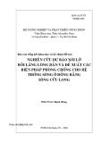
Figure 1: Typical block diagram of the demodulation and synchronization in the receiver of communication system.
the performance of DSP processors for the target applica-
tions. Some special function blocks also influence the per-
formance of application-specific DSPs. Notably, special func-
tional blocks such as square-distance-and-accumulate for
vector quantization, add-compare-select for the Viterbi al-
gorithm, and the Galois field operation for forward error-
control coding are provided in certain DSPs for baseband
operations [4,5,6,7,8]. For example, Lucent’s DSP 1618
performs Viterbi decoding using a coprocessor, which sup-
ports various decoding modes with control registers [5]. A
special function, called the mobile communication acceler-
ator (MCA), is incorporated into the design of MDSP-II to
accelerate the complex MAC operation [8].
Consequently, combining a dedicated, high performance
DSP core with some special functional blocks to produce a
highly integrated system is a current trend [9,10,11,12]. The
proposed design is parameterized and configurable and thus
can meet system requirements easily. The proposed DSP core
contains special blocks such as Hamming distance unit, sub-
word multiplier, dual MAC unit, rounded/saturation mode,
fixed-coefficient FIR filter, and slicer unit. The proposed DSP
core is designed to support the calculations in the demod-
ulation/synchronization part of the receiver. Figure 1 illus-
trates the typical block diagram of the demodulation and
synchronization in the receiver. Thus, this DSP core sup-
ports operations such as scaling, digital FIR filtering (both
fixed-coefficient filter for pulse shaping and adaptive filter for
equalization), symbol slicing, looping, complex multiplica-
tion, and so on.
In the aspect of low-power design, the memory access
operation is clearly the most power-consuming action in
DSPs. Various low-power techniques are also used in the
DSP developed here, including gray-code addressing and ad-
vanced hardware looping; pipeline sharing and low-power
data-path design are used to reduce power consumption. The
remainder of this paper is organized as follows: Section 2
presents the architecture of the proposed DSP. Section 3
then shows the design of the parameterized architecture and
the special functional blocks. Next, Section 4 discusses some
low-power design techniques used in this DSP core. Sub-
sequently, implementation and design results are demon-
strated in Section 5. Finally, Section 6 makes some conclu-
sions.
2. ARCHITECTURE OF THE DSP CORE
Figure 2 illustrates the overall architecture of the proposed
NCU DSP [9]. The NCU DSP is a fixed-point DSP core. The
grey blocks in Figure 2 are the special functional blocks and
are optional blocks that can be chosen by the user. The DSP
processor core itself is parameterized with several indepen-
dent parameters. Users can set the parameters so that the
DSP core fits the applications.
2.1. Bus and memory architecture
One of the characteristics of the DSP processor is that it can
move large amounts of data to or from memory rapidly and
efficiently. DSP processor has this characteristic because it
needs to process numerous calculations simultaneously. Tak-
ing FIR as an example, one tap operation must make three
accesses to memory, namely, coefficient access, data access,
and write-back data. If the memory bandwidth is not wide
enough, an operation must be split into several subopera-
tions before it can be completed. Consequently, memory ar-
chitecture is an important determinant of processor perfor-
mance.
Figure 3 illustrates the modified Harvard architecture
used in our work. The modified architecture contains one
program-memory bank and one data-memory bank with
separate program and data bus. The program and data mem-
ories are single-port and dual-port RAM, respectively. The
dual-port RAM indicates that the DSP processor simulta-
neously can make two accesses to RAM. This arrangement
provides a maximum of one program access and two data
accesses per instruction cycle to enhance memory access ca-
pacity.
Most of the DSP processors include one or more dedi-
cated data-address generation units (DAGU) for calculating
data address. NCU DSP supports three addressing modes,
namely, the indirect addressing, register direct addressing,
and immediate addressing modes, as listed in Table 1.The
indirect addressing mode requires one additional register

Low-Power Embedded DSP Core for Communication Systems 1357
NCU DSP processor function block
Data address generation
ARAU0, ARAU1
AR0∼AR7
Program address generation
PC, RC, BRC, RSA, REA
Program
memory
Data
memory
Slicer
PAB
PB
CAB
CB
DAB
DB
EAB
EB
T
MA MB
MW
Multiplier
Adder
SR
0
MC
R0
R1
R2
R3
R4
R5
R6
R7
MUX FIR
Delay
Reg.
Multiplier
MF
ALU
SR
MG
Hamming
distance
MH
Barrel
shifter
Basic function block
Optional special function block
Optional multifunction block
Figure 2: The block diagram of NCU DSP.
file, called the auxiliary register (ARx), for storing data-
memory address. Moreover, DSP processors usually need
to access data using special addressing methods in many
DSP algorithms. Hence, NCU DSP supports linear address-
ing, circular addressing, and bit-reversed address in the in-
direct addressing mode. The circular addressing mode can
be used to operate the FIR filter, and convolution and
correlation algorithm, while the FFT algorithm uses bit-
reversed addressing. These specialized functions not only re-
duce the programming burden but also enhance the per-
formance of DSP under conditions of smooth data access.
This enhanced performance is why the indirect addressing
mode is the most important addressing mode in the DSP
cores.
Figure 4a shows the straightforward method for calculat-
ing the bit-reversed addressing value. In Figure 4a,“A”rep-
resents the current address pointer value and “Step” repre-
sents the offset value, which is added to or subtracted from
the current pointer value. The internal carry propagation is
from MSB to LSB, differing from normal addition. Notably,
the bit-reversed address is calculated by adding or subtract-
ing the step value from MSB to LSB (if the step is +1, the
address value will be 0000,1000,0100,1100,0010,1010,...).
This circuit in Figure 4a uses a ripple adder to construct the
reversed carry propagation from MSB to LSB. However, the
circuit has nfull-adder (FA) delay time. This delay time of
ripple adder makes the instruction decode (ID) stage become
the critical path of DSP core. Figure 4b illustrates the new
bit-reversed addressing generation architecture. In Figure 4b,
“A” and “Step” are reordered by reversed connecting. The
ripple adder is replaced by a parallel adder which has less de-
lay time with respect to ripple adder. Finally, the output of
the parallel adder is the reversed order of the bit-reversed
value. The proposed new structure, Figure 4b, has smaller
delay time than that of Figure 4a.
2.2. I/O interface
Required transmission methods differ with data type. The
I/O interface of NCU DSP contains three categories, the di-
rect data access (DMA) mode, the handshaking mode, and

1358 EURASIP Journal on Applied Signal Processing
Data path
Address bus
Data bus
Data
memory
EB
EAB
DB
DAB
CB
CAB
PB
PAB Program
memory
PAGUDAGUI/O
Figure 3: The bus architecture of NCU DSP.
Table 1: Data addressing modes.
Type Operation Syntax Function Description
Indirect addressing
mode
∗ARx Address =ARx ARx contains the data-memory address.
∗ARx±Address =ARx
ARx =ARx±
After access, the address in ARx is incremented
or decremented by 1.
∗ARx ±0B Address =ARx
ARx =B(ARx ±AR0)
Afteraccess,AR0isaddedtoorsubtracted
from ARx with reverse carry propagation.
∗ARx ±0Address =ARx
ARx =ARx ±AR0
Afteraccess,AR0isaddedtoorsubtracted
from ARx.
∗ARx ±0% Address =ARx
ARx =circ(ARx ±AR0)
Afteraccess,AR0isaddedtoorsubtracted
from ARx with circular addressing.
Register direct
addressing mode ADD R0, R1, R2 R2 =R0 + R1 Access the content of register as operand
directly.
Immediate addressing
mode LAR # 1000 h AR0 AR0 =1000 h Give the destination register or memory
a value directly.
the merge mode. The DMA mode is to transfer data directly
from the outside of the DSP to the data memory of the DSP
core. The DMA mode is provided for transferring these data
quickly and conveniently. Notably, the DMA mode transfer
batch data. The transfer rate is the same with the clock in the
DSP core. The handshaking mode is for real-time data but
the data rate is not regular. The handshaking signals are re-
quired to perform the data transfer in this mode. The merge
mode is to transfer data in regular clock rate which is slower
than the internal clock of DSP core. In DMA mode, the DSP
core is halt until the data transfer is finished. The DSP core is
running when data are transferred in merge mode and hand-
shaking mode. Notably, the data transfer in the handshaking
and merge modes occurs between the data outside the NCU
DSP core and the host programmable interface (HPI) mem-
ory. The HPI memory resembles a buffer of data memory.
2.3. Pipeline stage
The NCU-DSP contains six pipeline stages, namely, instruc-
tion fetch (IF) stage, ID stage, operand fetch (OP) stage,

Low-Power Embedded DSP Core for Communication Systems 1359
Cn
Sn
AnStepn
FAn
Cn−1···C3
A2
S2
Step2
FA2C2
A1Step1
FA1
S1
C1
A0Step0
FA0C0
S0
(a)
Sn−1... S
2S1S0
N-bit parallel adder
A0A1A2... A
n−1Step0Step1Step2...Stepn−1
An−1... A
2A1A0Stepn−1...Step2Step1Step0
···
···
···
···
···
···
(b)
Figure 4: (a) Previous and (b) new bit-reversed addressing generator architecture in NCU DSP.
Data
path2
Data
path1
Dual-port
memory
ARAU
Stack/
memory/
selection
Clk
Decoder2Decoder1
IF ID OP EX1 EX2 WB
Figure 5: The pipeline stages of NCU DSP.
execution one (EX1) stage, execution two (EX2) stage, and
write-back (WB) stage, as shown in Figure 5. To accelerate
the performance of NCU-DSP, data-path calculation was
split into the EX1 and EX2 stages. The most troublesome
problems encountered using the pipelining technique were
data hazards [13]. Data hazards occur when the next in-
struction needs to use data that is still being calculated by
the present instruction. Six clock cycles are required for the
present instruction to calculate the data and write it back
to memory. The next instruction fetches the data just three
stages behind (OP stage). Consequently, the programmer
needs to insert some useless instructions (e.g., NOP) to avoid
the data hazard. To reduce the penalties arising from data
hazards, this work adopts the data-forwarding technique in
[13,14].
The following example describes an example of data haz-
ard:
·········
STL A, ∗AR3
MAC2 ∗AR3,∗AR2,A
·········
The ∗AR3 is not ready until “STL” completes in the
sixth stage. Thus, three NOPs must be added between “STL”
and “MAC2.” Figure 6 illustrates the data-forwarding tech-
nique, which reduces the required number of NOPs to just
one.
![Mẫu Báo cáo tiến độ thực hiện đề tài [chuẩn nhất]](https://cdn.tailieu.vn/images/document/thumbnail/2025/20250318/tuongmotranh/135x160/1241742262566.jpg)