Virtual LANs
With a growing number of users on a network comes the challenges of management, so it is not
surprising that virtual local-area networks (VLANs) have become a popular feature of switches.
VLANs ease the administrative duties of the network engineer. A VLAN gives an administrator
the ability to remove the physical restrictions of the past and control a user’s Layer 3 network
address regardless of his or her physical location.
Other advantages of VLANs include enhanced security features, easierto-control broadcasts, and
the ability to distribute traffic. Cisco Catalyst switches have the ability to perform numerous
functions to enhance and ease the implementation of VLANs.
The use of trunking allows a VLAN to span multiple switches that can be separated by small or
large areas. Cisco also has implemented the trunking feature in many of its routing products,
resulting in many helpful and interesting network designs.
VLAN Defined
A VLAN can be defined in two words—broadcast domain. VLANs are broadcast domains, and
as we learned in Chapter 1, a broadcast domain is a Layer 3 network. A switch defines a VLAN,
and the switch’s ports will have membership in one of the defined VLANs. For example, in
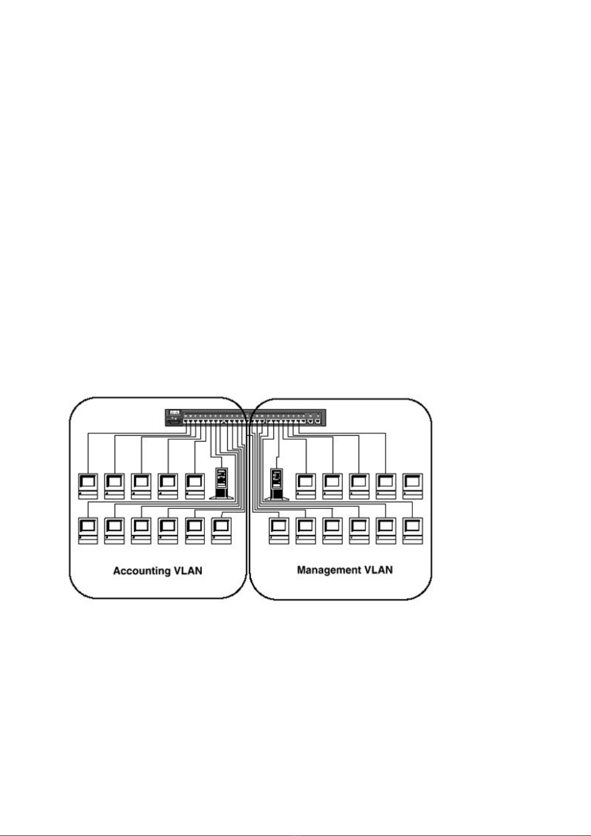
Figure 4-1, a switch has ports defined in two VLANs, Accounting and Management.
Figure 4-1 Two VLANs on a Catalyst 1900
Ports 1 through 12 have been assigned to the Accounting VLAN, and ports 13 through 24 have
been assigned to the Management VLAN. The switch will not allow broadcasts to flow between
VLANs, thus logically segmenting the network (Figure 4-2).
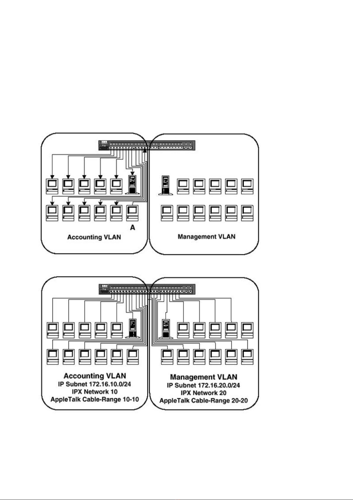
If workstation A were to send a broadcast, all stations on the Accounting VLAN would receive
it. However, the switch would not forward the broadcast to any of the Management VLAN
ports. In fact, a switch would not forward a frame from one VLAN to another unless it was a
multilayer switch, which will be discussed later. Some of you may still be thinking about
Chapter 1 when I said, “A router is the only device that can logically segment.” Technically, this
is incorrect. A switch can logically segment, but in the real world it is ludicrous to use a switch
without a router as a device to logically segment because traffic will never be allowed to pass
between VLANs. This is a very unlikely scenario and is pointless to discuss.
The workstations in the Accounting VLAN will be in a completely different broadcast domain
from the Management VLAN’s users and therefore will be in an entirely different IP subnet,
IPX network, and Appletalk cable-range. In Figure 4-3, the Accounting VLAN is assigned the
IP subnet 172.16.10.0/24, the IPX Network 10, and the Appletalk cable-range 10-10. The
Management VLAN is assigned the IP subnet 172.16.20.0/24, the IPX network 20, and the
Appletalk cable-range 20-20. Traffic from one VLAN will have no effect on the other,
regardless of their physical locations on the floor.
Figure 4-2 Broadcasts Are Kept within All Ports in the VLAN
Figure 4-3 IP Subnets, IPX Network, and Appletalk Cable-Range Assignments for Each VLAN
Cisco’s implementation of VLANs is port-centric. The port to which a node is connected will
define the VLAN in which it resides. How a port gets assigned to a VLAN can vary with Cisco
Catalyst switches. There are two methods of assigning ports to VLANs, static and dynamic.
Static VLANs
The static VLAN procedure is to administratively assign a port to a VLAN. An engineer
determines which ports he or she would like on a particular VLAN and statically maps that
VLAN to a port. For example, in Figure 4-1, the Accounting VLAN is defined to be any node
connected to ports 1 through 12. An engineer would enter the appropriate commands, either
from the command line interface (CLI) of the switch, an SNMP management station, or Cisco’s
software management tool CiscoWorks for Switched Internetworks (CWSI) to assign ports 1
through 12 to the Accounting VLAN. This method can be very time-consuming because the
engineer has to manually enter the commands necessary to map the ports to their appropriate
VLANs. However, it is the most common method of assigning a port to a VLAN.
Dynamic VLANs
A dynamic VLAN exists when a port decides what VLAN it belongs in for itself. No, this is not
The Terminator or The Forbin Project becoming nonfiction; rather, it is a simple mapping that
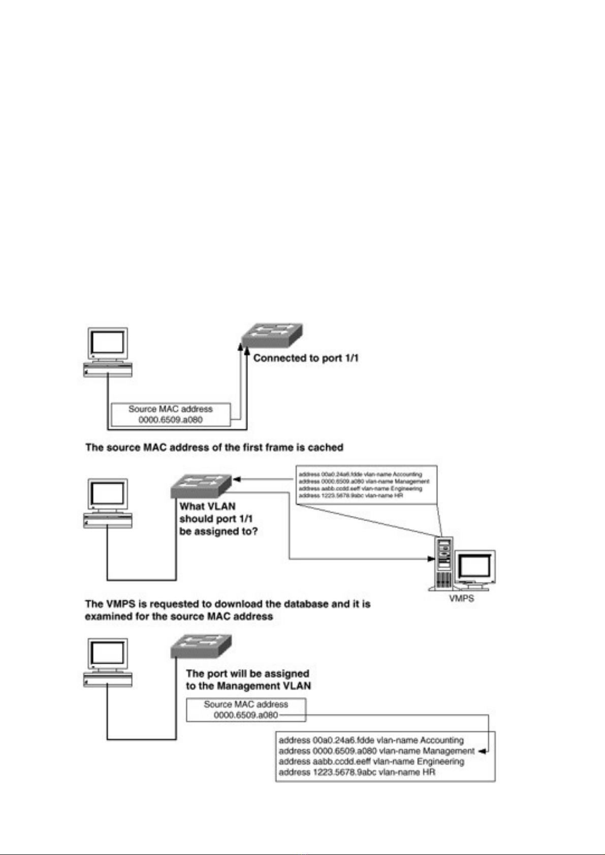
occurs based on a database created by an engineer. When a port that is assigned to be a dynamic

VLAN port becomes active, the switch caches the source MAC address of the first frame
(Figure 4-4).
It then makes a request to an external server called a VLAN management policy server (VMPS)
that contains a text file with MAC addresses to VLAN mappings. The switch will download this
file and examine it for the source MAC address it has cached for the port in question. If the
MAC address is found in the table, the port will be assigned to the listed VLAN. If the MAC
address is not in the table, the switch will use the default VLAN, if defined. In the event that the
MAC address is not listed in the table and there is no default VLAN, the port will not become
active. This can be a very good method of security.
Dynamic VLANs on the surface appear to be very advantageous, but building of the database
can be a very painstaking and tortuous task. If a network has thousands of workstations, there
will be a lot of typing. Assuming that one could survive the process, there are still other issues
with dynamic VLANs. Keeping the database current can become an ongoing time-consuming
process.
Configuring VLANs
Once the management domain has been created, VLANs may be created. There are five
properties of a VLAN that can be defined when creating the VLAN (Table 8-2).
In order to set the VLAN number and name, the following syntax is used:
Switch_A> (enable) set vlan [vlan_number] name [VLAN_name]
For example, to create a VLAN numbered 10 and named FSU and a VLAN numbered 20 and
named Duke:
Table 8-2 VLAN Parameters
Parameter Description
Number The VLAN number is a unique number on the management
domain to identify the broadcast domain.
Type
The VLAN type defines the type of VLAN. When using Ethernet
or FDDI, the VLAN type will be “Ethernet.” When trunking over
FDDI, the VLAN type will be FDDI. When using Token Ring, the
VLAN type will be either TR-CRF or TR-BRF.
Name The VLAN name is for documentation purposes and has no
functional effect on the switch.
MTU The maximum transmission unit (MTU) of frames for the VLAN.
SAID Security association and identifier (used for FDDI only).
Switch_A> (enable) set vlan 10 name FSU
Vlan 10 configuration successful
Switch_A> (enable) set vlan 20 name Duke
Vlan 20 configuration successful
The show vlan command can be used to verify the VLAN settings:

Switch_A> (enable) sh vlan
VLAN Name Status IfIndex Mod/Ports, Vlans
-------- ------------------------- -------- -------- ----------------
1 default active 5 1/1-2
3/1-24
5/1-12
10 FSU active 46
20 Duke active 47
1002 fddi-default active 6
1003 token-ring-default active 9
1004 fddinet-default active 7
1005 trnet-default active 8
Once the VLAN has been created on one switch, it will be advertised via VTP to all switches in
the management domain.
To assign ports to a VLAN, the set vlan command is used again with a different syntax:
Switch_A> (enable) set vlan [vlan_num] [module/ports]
Multiple ports may be listed with a hyphen, if they are in numerical order, or a comma.
For example, to assign the first 12 ports on module 3 to VLAN 10 and the last 12 ports on
module 3 to VLAN 20:
Switch_A> (enable) set vlan 10 3/1-12
VLAN 10 modified.
VLAN 1 modified.
VLAN Mod/Ports
---- --------------------------------------------
10 3/1-12
Switch_A> (enable) set vlan 20 3/13-23,24
VLAN 20 modified.
VLAN 1 modified.
VLAN Mod/Ports
---- --------------------------------------------
20 3/13-24
Switch_A> (enable)
The results will indicate that both the VLAN to which the ports were assigned previously and
the VLAN that is being assigned are being modified.
To verify that the ports have been properly assigned:
Switch_A> (enable) sh vlan
VLAN Name Status IfIndex Mod/Ports, Vlans
-------- -------------------------- ------- -------- ----------------
1 default active 5 1/1-2
5/1-12
10 FSU active 46 3/1-12
20 Duke active 47 3/13-24
1002 fddi-default active 6
1003 token-ring-default active 9
1004 fddinet-default active 7
1005 trnet-default active 8


%20--%3e%3cdefs%3e%3cstyle%3e%20.st0%20{%20fill:%20%23fff;%20}%20.st1%20{%20fill:%20%237800fa;%20}%20%3c/style%3e%3c/defs%3e%3cpath%20class='st1'%20d='M117.78,12.18H43.11c2.9,3.47,4.65,7.94,4.65,12.82,0,5.6-2.3,10.66-6.01,14.29h76.02l7.22-13.56-7.22-13.56Z'/%3e%3cg%3e%3cpath%20class='st0'%20d='M53.58,26.17h-.59v-1.46h.59v-4.96h2.83c1.78,0,2.67.94,2.67,2.82v5.76c0,1.87-.89,2.81-2.67,2.81h-2.83v-4.96ZM55.36,21.37v3.34h1.1v1.46h-1.1v3.34h1.01c.61,0,.91-.37.91-1.1v-5.93c0-.74-.3-1.1-.91-1.1h-1.01Z'/%3e%3cpath%20class='st0'%20d='M65.99,31.14h-1.8l-.31-2.07h-2.19l-.31,2.07h-1.64l1.82-11.39h2.62l1.82,11.39ZM65.28,18.04c-.25.46-.51.77-.75.94-.21.15-.47.22-.79.22-.26,0-.57-.07-.92-.22l-.38-.15c-.14-.05-.26-.07-.37-.07-.3,0-.53.18-.71.54l-.91-.68c.25-.46.51-.77.75-.94.21-.14.48-.21.79-.21.26,0,.57.07.92.21l.38.15c.14.05.26.07.37.07.3,0,.53-.18.71-.54l.91.68ZM61.91,27.52h1.73l-.87-5.76-.87,5.76Z'/%3e%3cpath%20class='st0'%20d='M74.53,26.89v1.52c0,1.91-.89,2.86-2.67,2.86s-2.67-.95-2.67-2.86v-5.93c0-1.91.89-2.86,2.67-2.86s2.67.95,2.67,2.86v1.11h-1.69v-1.22c0-.75-.31-1.12-.93-1.12s-.93.37-.93,1.12v6.15c0,.74.31,1.11.93,1.11s.93-.37.93-1.11v-1.63h1.69Z'/%3e%3cpath%20class='st0'%20d='M81.4,31.14h-1.8l-.31-2.07h-2.19l-.31,2.07h-1.64l1.82-11.39h2.62l1.82,11.39ZM75.9,19.2l1.52-1.91h1.71l1.51,1.91h-1.61l-.76-.95-.75.95h-1.61ZM77.32,27.52h1.73l-.87-5.76-.87,5.76ZM83.1,15.99l-1.76,1.91h-1.26l1.17-1.91h1.86Z'/%3e%3cpath%20class='st0'%20d='M84.86,19.75c1.78,0,2.67.94,2.67,2.82v1.48c0,1.87-.89,2.81-2.67,2.81h-.85v4.28h-1.79v-11.39h2.64ZM84.01,21.37v3.86h.85c.58,0,.87-.36.87-1.08v-1.71c0-.71-.29-1.07-.87-1.07h-.85Z'/%3e%3cpath%20class='st0'%20d='M93.51,19.75c1.78,0,2.67.94,2.67,2.82v1.48c0,1.87-.89,2.81-2.67,2.81h-.85v4.28h-1.79v-11.39h2.64ZM92.66,21.37v3.86h.85c.58,0,.87-.36.87-1.08v-1.71c0-.71-.29-1.07-.87-1.07h-.85Z'/%3e%3cpath%20class='st0'%20d='M98.8,31.14h-1.79v-11.39h1.79v4.88h2.03v-4.88h1.83v11.39h-1.83v-4.88h-2.03v4.88Z'/%3e%3cpath%20class='st0'%20d='M105.36,24.55h2.46v1.62h-2.46v3.34h3.09v1.63h-4.88v-11.39h4.88v1.63h-3.09v3.18ZM108.17,17.29l-1.76,1.91h-1.26l1.17-1.91h1.86Z'/%3e%3cpath%20class='st0'%20d='M112.2,19.75c1.78,0,2.67.94,2.67,2.82v1.48c0,1.87-.89,2.81-2.67,2.81h-.85v4.28h-1.79v-11.39h2.64ZM111.35,21.37v3.86h.85c.58,0,.87-.36.87-1.08v-1.71c0-.71-.29-1.07-.87-1.07h-.85Z'/%3e%3c/g%3e%3ccircle%20class='st1'%20cx='25'%20cy='25'%20r='20'/%3e%3cpath%20class='st0'%20d='M32.78,19.27c2.92,0,4.43,2.55,5.28,5.33l.71,2.17c.14.38-.33.75-.71.75h-5.61c.19-.33.24-.71.09-1.08l-.75-2.45c-.43-1.32-.99-2.64-1.79-3.77.75-.57,1.65-.94,2.78-.94h0ZM25,18.38c3.25,0,4.9,2.78,5.89,5.89l.76,2.45c.14.42-.33.8-.8.8h-11.69c-.42,0-.94-.38-.8-.8l.75-2.45c.99-3.11,2.64-5.89,5.89-5.89h0ZM25,11.35c1.74,0,3.11,1.37,3.11,3.11s-1.37,3.11-3.11,3.11-3.11-1.41-3.11-3.11,1.41-3.11,3.11-3.11h0ZM17.27,19.27c1.08,0,1.98.38,2.73.94-.8,1.13-1.37,2.45-1.74,3.77l-.8,2.45c-.14.38-.05.75.09,1.08h-5.56c-.42,0-.9-.38-.75-.75l.71-2.17c.9-2.78,2.41-5.33,5.33-5.33h0ZM17.27,12.91c1.51,0,2.78,1.27,2.78,2.83s-1.27,2.83-2.78,2.83-2.83-1.27-2.83-2.83,1.27-2.83,2.83-2.83h0ZM32.78,12.91c1.56,0,2.78,1.27,2.78,2.83s-1.23,2.83-2.78,2.83-2.83-1.27-2.83-2.83,1.27-2.83,2.83-2.83h0ZM27.07,28.56v.09c0,.57-.24,1.08-.61,1.46h0v.05c-.38.33-.9.57-1.46.57s-1.08-.24-1.46-.61h0c-.38-.38-.61-.9-.61-1.46v-.09h1.41v.09c0,.19.05.38.19.47v.05c.09.09.28.19.47.19s.38-.09.47-.19v-.05c.14-.09.24-.28.24-.47t-.05-.09h1.41ZM30.99,28.56v.09c0,1.65-.66,3.16-1.74,4.24-1.08,1.08-2.59,1.79-4.24,1.79s-3.16-.71-4.24-1.79l-.05-.05c-1.04-1.08-1.7-2.55-1.7-4.2v-.09h1.41v.09c0,1.27.47,2.4,1.27,3.25h.05c.85.85,1.98,1.37,3.25,1.37s2.4-.52,3.25-1.37c.85-.8,1.37-1.98,1.37-3.25v-.09h1.37ZM34.99,28.56v.09c0,2.78-1.13,5.28-2.92,7.07-1.79,1.79-4.29,2.92-7.07,2.92s-5.23-1.13-7.07-2.92c-1.79-1.79-2.92-4.29-2.92-7.07v-.09h1.41v.09c0,2.4.94,4.53,2.5,6.08,1.56,1.56,3.72,2.5,6.08,2.5s4.52-.94,6.08-2.5c1.56-1.56,2.5-3.68,2.5-6.08v-.09h1.41Z'/%3e%3c/svg%3e)