TM 5-815-1/AFR 19-6
7-7
severe pitting in stainless steels. This condition is fre- resistant to oxidizing acid environments, but are
quently encountered in an incinerator which burnsattached by acids under reducing conditions. The
large quantities of disposable polyvinyl chloride (PVC) equipment designer should select materials based on
materials. individual case conditions including temperature, abra-
b. Temperature. Corrosion rates generally increasesion, pH, etc.
with increases in exhaust temperatures. This is due to
the increased mobility of ions and increased reaction
rates. However, in cases where the corrosion process
is accelerated by the presence of oxygen, increasing the
acid temperature eventually boils out dissolved oxygen,
rapidly diminishing corrosion rate. This is the case with
Monel, a nickel-copper alloy.
c.Velocity. Often the corrosion resistance of an alloy
depends on the existence of an adhering oxide layer on
its surface. A high exhaust gas velocity can remove or
erode the surface layer. Once removed, this layer can-
not be renewed because the oxide film is washed away
as it forms.
d. State of oxidation. Under reducing condition,
Monel is very resistant to moderate sulfuric-acid con-
centrations. Under oxidizing conditions, or in the pres-
ence of oxidizing ions, however, very rapid corrosion
occurs. The reverse is true of stainless steels which are
7-6. Auxiliary equipment
a. Gas transport.
(1) Ducts and stacks. Large boiler plant stacks
have a wind shield of reinforced concrete or
of steel, with a separate inner flue or
numerous flues of steel, acid-resistant brick,
and occasionally, stainless steel. The space
between the inner flue and the outer wind
shield may be insulated with a mineral wool
wrapping. This is to prevent the condensa-
tion of acid dew on the inside of the metal
chimney, which occurs below dew point
temperature, and also to prevent acid “smut”
from being blown out of the chimney. Acid
smut is a term for ash particles contaminated
with acid. It is heavy and tends to fall out of
the gas plume soon after exiting from the
Simpo PDF Merge and Split Unregistered Version - http://www.simpopdf.com

TM 5-815-1/AFR 19-6
7-8
stack. In smaller plants, stacks may be apressure piping. Considerations must also be
single wall steel construction with insulation made for weatherproofing against freezing
and lagging on the outer surface. For wetconditions.
scrubbing practice, chimneys for vapor-satu- (2) Pumps. Centrifugal pumps are used to
rated gases containing corrosive substances supply the scrubbing liquid or recycled slurry
may be made of rubber-lined steel,to the scrubber nozzles at the required
fiberglass-reinforced resin or othervolume flow rate and pressure. Where no
corrosion-resistant material. With materialssolids are present in the liquid, bare metal
that have a limited maximum temperature,pumps, either iron or stainless steel
provisions must be made to protect the stack construction, are used. In recycle systems
from high temperatures because of loss ofwith solids in the liquid, special rubber-lined
scrubbing liquid. Chimney or stack velocities or hard-iron alloy pumps are used to control
are generally 30 ft/ sec to prevent re-erosion of the pump internals. These are
entrainment of moisture from the stack wall generally belt driven to allow selection of the
which would rain down around the plant.proper speed necessary for the design
Sometimes cones are fitted at the top to give capacity and head. Solids content must still
exit velocities as high as 75 ft/sec. The chief be controlled to limit the maximum slurry
reason for high velocities is to eject the gases consistency to meet the scrubber and pump
well away from the top of the stack torequirements.
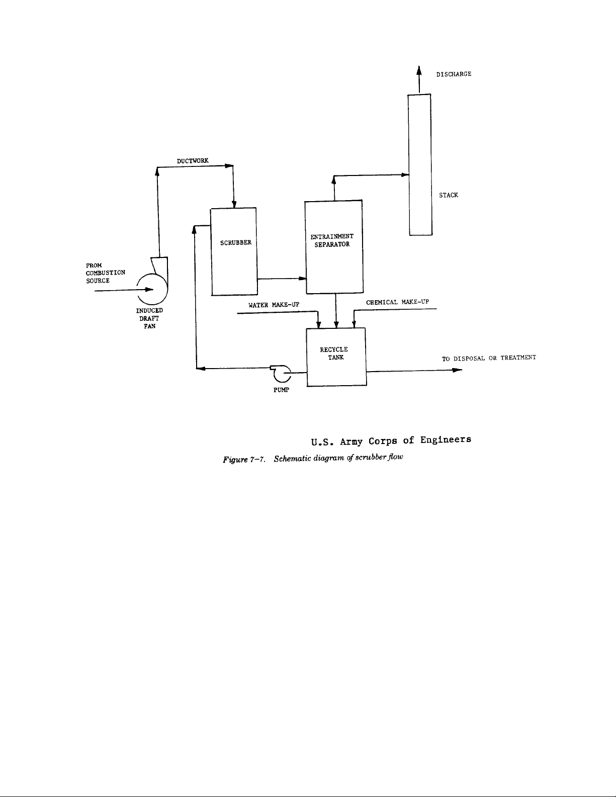
increase the effective height and to avoidc. Entrainment separation. After the wetted gas
downwash. Downwash can damage thestream leaves the scrubbing section, entrained liquid
metal structure supporting the stack, thedroplets must be removed. Otherwise they would rain
stack itself, or the outside steel of a linedout of the stack and fall on the surrounding area.
metal stack. (For a more detailed analysis of Removal can be by gravity separation in an expanded
the meteorological considerations involvedvessel with lowered velocity or a cyclonic separator
in stack design, see chapter 4.) can swirl out the droplets against the vessel wall.
(2) Fans. In a wet scrubber system the preferred Knitted wire or plastic mesh demisters or chevron or
location for the boiler or incinerator“zig-zag” vanes can be located at the scrubber outlet to
induced-draft fan is upstream of thecatch any droplets.
scrubber. This eliminates the need ford. Process measurement and control. The scrubber
special corrosion-resistant constructioncontrol system should be designed to follow variations
required to handle the wet downstream gas. in the boiler or incinerator gas flow and contaminant
The fan should be selected to resist build-up load to maintain outlet emissions in compliance with
of dry ash or erosion of the rotor surfaces.selected criteria.
For high dust load applications a radial blade (1) Measurements. Measurement of data from
or radial tip blade fan is more durable. In athe process to provide proper control should
dry scrubber application the fan should beinclude inlet gas flow rate, temperature and
downstream of the scrubber in the clean gas pressure, scrubber gas pressure drop, liquid
stream. Here a more efficient air-foil orpressure, flow rate, solids consistency, pH,
squirrel-cage rotor can be used. and outlet gas temperature. Selection of
b. Liquid transport. instrumentation hardware should be on an
(1) Pipework. For most scrubbing duties, theindividual application basis.
liquid to be conveyed will be corrosive.(2) Control. Pressure drop across a scrubber can
There exists a wide variety of acid resistantbe referenced as an indication of
pipework to choose from, but generallyperformance following initial or periodic,
speaking, rubber-lined steel pipe has highoutlet gas testing. In a variable throat
versatility. It is easy to support, has theventuri, for instance, this pressure drop can
strength of steel, will withstand increases in be used to control the throat opening,
temperature for a short time and will notmaintaining constant performance under
disintegrate from vibration or liquidvarying gas volume flow rates. Measurement
hammer. Fiberglass filament wound plasticof scrubber slurry solids consistency can be
pipe is also suitable for a very wide range of used to control bleed-off of high solids slurry
conditions of temperature, pressure, andand make-up with fresh water. If sulfur
chemicals. The chief disadvantage of rubber- dioxide (SO ) is being controlled then
lined pipe is that it cannot be cut to size and measurement of scrubber liquid pH can
has to be precisely manufactured withcontrol make-up of caustic to maintain
correct lengths and flange drilling. Siteefficiency of SO removal. Complete
fabrication is not possible. Most piping isspecification or design of a control system
manufactured to ANSI specifications formust be on a case-by-case basis.
2
2
Simpo PDF Merge and Split Unregistered Version - http://www.simpopdf.com

TM 5-815-1/AFR 19-6
7-9
7-7. Advantages and disadvantages b. Disadvantages. The disadvantages of selecting
a. Advantages. The advantages of selecting scrub-
bers over other collection devices are:
—Capability of gas absorption for removal of
harmful and dangerous gases,
—High efficiency of particulate removal,
—Capability of quenching high temperature
exhaust gases,
—Capability of controlling heavy particulate
loadings,
scrubbers over other collection devices are:
—Large energy usage for high collection effi-
ciency,
—High maintenance costs,
—Continuous expenses for chemicals to
remove gaseous materials,
—Water supply and disposal requirements,
—Exhaust gas reheat may be necessary to
maintain plume dispersion,
—Weather proofing is necessary to prevent
freezeup of equipment.
Simpo PDF Merge and Split Unregistered Version - http://www.simpopdf.com

TM 5-815-1/AFR 19-6
8-1
CHAPTER 8
ELECTROSTATIC PRECIPITATORS
8-1. Electrostatic precipitator (ESP) plate design. It has the advantage of collecting more
An electrostatic precipitator is a device which removes
particles from a gas stream. It accomplishes particle
separation by the use of an electric field which:
—imparts a positive or negative charge to the
particle,
—attracts the particle to an oppositely charged
plate or tube,
—removes the particle from the collection
surface to a hopper by vibrating or rapping
the collection surface.
8-2. Types of electrostatic precipitators
a. Two stage ESPs. Two stage ESPs are designed so single stage, parallel plate design. They are smaller in
that the charging field and the collecting field are inde- construction than hot precipitator types because they
pendent of each other. The charging electrode ishandle smaller gas volumes due to the reduced tem-
located upstream of the collecting plates. Two stageperature. Cold precipitators are most effective at col-
ESPs are used in the collection of fine mists. lecting particles of low resistivity since particle
b. Single stage ESPs. Single stage ESPs are designed resistance to collection is greater at lower tem-
so that the same electric field is used for charging and peratures. These precipitators are subject to corrosion
collecting particulate s Single stage ESPs are the most due to the condensation of acid mist at the lower tem-
common type used for the control of particulateperatures.
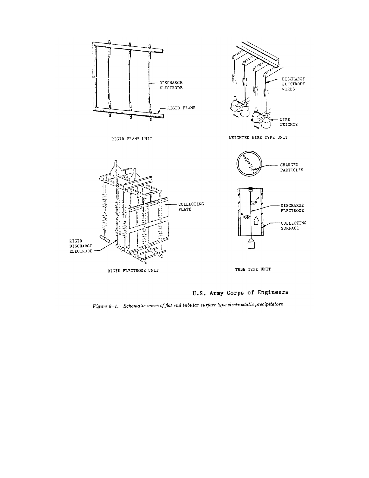
emissions and are either of tube or parallel plate type
construction. A schematic view of the tube and parallel
plate arrangement is given in figure 8-1.
(1) The tube type precipitator is a pipe with a
discharge wire running axially through it. Gas stream entering the precipitator. Wet precipitators
flows up through the pipe and collected par- enhance the collection efficiency of particulates by
ticulate is discharged from the bottom. Thisreducing reentrainment from the collection plates. Care
type of precipitator is mainly used to handleshould be taken so that water addition does not lower
small gas volumes. It possesses a collectiongas temperature below the dewpoint temperature, thus
efficiency comparable to the parallel plateallowing the formation of acids. A wet precipitator can
types, usually greater than 90 percent. Water be of either plate or tube type construction.
washing is frequently used instead of rapping
to clean the collecting surface. 8-4. Applications
(2) Parallel plate precipitators are the most com-
monly used precipitator type. The plates are
usually less than twelve inches apart with the
charging electrode suspended vertically
between each plate. Gas flow is horizontal
through the plates.
8-3. Modes of operation.
All types of ESPs can be operated at high or low tem- reviewed.
peratures, with or without water washing (table 8-1).
a. Hot precipitation. A hot precipitator is designed
to operate at gas temperatures above 600 degreesindustry to control emissions from coal-fired boilers.
Fahrenheit and is usually of the single stage, parallelCold type precipitators are the prevalent type because
particulate from the hot gas stream because particle
resistance to collection decreases at higher
temperatures. The ability to remove particles from the
collection plates and hoppers is also increased at these
temperatures. However, hot precipitators must be large
in construction in order to accommodate the higher
specific volume of the gas stream.
b.Cold precipitation. Cold precipitators are
designed to operate at temperatures around 300
degrees Fahrenheit. The term “cold” is applied to any
device on the low temperature side of the exhaust gas
heat exchanger. Cold ESPs are also generally of the
c. Wet precipitation. A wet precipitator uses water
to aid in cleaning the particulate collection plates. It
may employ water spray nozzles directed at the collec-
tion plates, or inject a fine water mist into the gas
Electrostatic precipitators are among the most widely
used particulate control devices. They are used to con-
trol particulate emissions from the electric utility
industry, industrial boiler plants, municipal incin-
erators, the non-ferrous, iron and steel, chemical,
cement, and paper industries. It is outside the scope of
this manual to include all of these application areas.
Only applications to boilers and incinerators will be
a. Boiler application. Parallel plate electrostatic
precipitators are commonly employed in the utility
Simpo PDF Merge and Split Unregistered Version - http://www.simpopdf.com
TM 5-815-1/AFR 19-6
8-2
they are most easily retrofitted. In the design of newc. Incinerator application. Until relatively recently,
installations, the use of hot precipitators has becomeESPs were used for pollution control on incineration
more common, because of the greater use of lowerunits only in Europe. In the United States, however, the
sulfur fuels. Low sulfur fuels have higher particleESP is now being viewed as one of the more effective
resistivity and therefore particulate emissions are more methods for the control of emissions from incinerators.
difficult to control with cold precipitation. Figure 8-2 The major problem associated with the use of
may be used for estimating whether hot precipitators or precipitators on incinerators is high gas temperatures.
cold precipitators should be selected for a particularTemperatures up to 1800 degrees Fahrenheit can be
sulfur content of coal. encountered at the incinerator outlet. These tem-
b. Wood refuse boiler applications. An ESP can be peratures must be reduced before entering a pre-
used for particulate collection on a wood fired boilercipitator. Several methods can be used to accomplish
installation if precautions are taken for fire prevention. this temperature reduction:
The ESP should be preceded by some type of—mixing of the gas with cooler air;
mechanical collection device to prevent hot glowing—indirect cooling such as waste heat boilers,
char from entering the precipitator and possibly starting —evaporative cooling in which droplets of
a fire. water are sprayed into the gas.
Simpo PDF Merge and Split Unregistered Version - http://www.simpopdf.com


![Đề cương tuabin lò hơi [mới nhất]](https://cdn.tailieu.vn/images/document/thumbnail/2015/20150723/vinadnh/135x160/1764936_356.jpg)


![Giáo trình Tính toán thiết kế hệ thống máy lạnh và điều hoà không khí (CĐ) - Trường Cao đẳng Công nghiệp Thanh Hóa [Mới nhất]](https://cdn.tailieu.vn/images/document/thumbnail/2026/20260511/hoabattu2026/135x160/70831778842526.jpg)


%20--%3e%3cdefs%3e%3cstyle%3e%20.st0%20{%20fill:%20%23fff;%20}%20.st1%20{%20fill:%20%237800fa;%20}%20%3c/style%3e%3c/defs%3e%3cpath%20class='st1'%20d='M117.78,12.18H43.11c2.9,3.47,4.65,7.94,4.65,12.82,0,5.6-2.3,10.66-6.01,14.29h76.02l7.22-13.56-7.22-13.56Z'/%3e%3cg%3e%3cpath%20class='st0'%20d='M53.58,26.17h-.59v-1.46h.59v-4.96h2.83c1.78,0,2.67.94,2.67,2.82v5.76c0,1.87-.89,2.81-2.67,2.81h-2.83v-4.96ZM55.36,21.37v3.34h1.1v1.46h-1.1v3.34h1.01c.61,0,.91-.37.91-1.1v-5.93c0-.74-.3-1.1-.91-1.1h-1.01Z'/%3e%3cpath%20class='st0'%20d='M65.99,31.14h-1.8l-.31-2.07h-2.19l-.31,2.07h-1.64l1.82-11.39h2.62l1.82,11.39ZM65.28,18.04c-.25.46-.51.77-.75.94-.21.15-.47.22-.79.22-.26,0-.57-.07-.92-.22l-.38-.15c-.14-.05-.26-.07-.37-.07-.3,0-.53.18-.71.54l-.91-.68c.25-.46.51-.77.75-.94.21-.14.48-.21.79-.21.26,0,.57.07.92.21l.38.15c.14.05.26.07.37.07.3,0,.53-.18.71-.54l.91.68ZM61.91,27.52h1.73l-.87-5.76-.87,5.76Z'/%3e%3cpath%20class='st0'%20d='M74.53,26.89v1.52c0,1.91-.89,2.86-2.67,2.86s-2.67-.95-2.67-2.86v-5.93c0-1.91.89-2.86,2.67-2.86s2.67.95,2.67,2.86v1.11h-1.69v-1.22c0-.75-.31-1.12-.93-1.12s-.93.37-.93,1.12v6.15c0,.74.31,1.11.93,1.11s.93-.37.93-1.11v-1.63h1.69Z'/%3e%3cpath%20class='st0'%20d='M81.4,31.14h-1.8l-.31-2.07h-2.19l-.31,2.07h-1.64l1.82-11.39h2.62l1.82,11.39ZM75.9,19.2l1.52-1.91h1.71l1.51,1.91h-1.61l-.76-.95-.75.95h-1.61ZM77.32,27.52h1.73l-.87-5.76-.87,5.76ZM83.1,15.99l-1.76,1.91h-1.26l1.17-1.91h1.86Z'/%3e%3cpath%20class='st0'%20d='M84.86,19.75c1.78,0,2.67.94,2.67,2.82v1.48c0,1.87-.89,2.81-2.67,2.81h-.85v4.28h-1.79v-11.39h2.64ZM84.01,21.37v3.86h.85c.58,0,.87-.36.87-1.08v-1.71c0-.71-.29-1.07-.87-1.07h-.85Z'/%3e%3cpath%20class='st0'%20d='M93.51,19.75c1.78,0,2.67.94,2.67,2.82v1.48c0,1.87-.89,2.81-2.67,2.81h-.85v4.28h-1.79v-11.39h2.64ZM92.66,21.37v3.86h.85c.58,0,.87-.36.87-1.08v-1.71c0-.71-.29-1.07-.87-1.07h-.85Z'/%3e%3cpath%20class='st0'%20d='M98.8,31.14h-1.79v-11.39h1.79v4.88h2.03v-4.88h1.83v11.39h-1.83v-4.88h-2.03v4.88Z'/%3e%3cpath%20class='st0'%20d='M105.36,24.55h2.46v1.62h-2.46v3.34h3.09v1.63h-4.88v-11.39h4.88v1.63h-3.09v3.18ZM108.17,17.29l-1.76,1.91h-1.26l1.17-1.91h1.86Z'/%3e%3cpath%20class='st0'%20d='M112.2,19.75c1.78,0,2.67.94,2.67,2.82v1.48c0,1.87-.89,2.81-2.67,2.81h-.85v4.28h-1.79v-11.39h2.64ZM111.35,21.37v3.86h.85c.58,0,.87-.36.87-1.08v-1.71c0-.71-.29-1.07-.87-1.07h-.85Z'/%3e%3c/g%3e%3ccircle%20class='st1'%20cx='25'%20cy='25'%20r='20'/%3e%3cpath%20class='st0'%20d='M32.78,19.27c2.92,0,4.43,2.55,5.28,5.33l.71,2.17c.14.38-.33.75-.71.75h-5.61c.19-.33.24-.71.09-1.08l-.75-2.45c-.43-1.32-.99-2.64-1.79-3.77.75-.57,1.65-.94,2.78-.94h0ZM25,18.38c3.25,0,4.9,2.78,5.89,5.89l.76,2.45c.14.42-.33.8-.8.8h-11.69c-.42,0-.94-.38-.8-.8l.75-2.45c.99-3.11,2.64-5.89,5.89-5.89h0ZM25,11.35c1.74,0,3.11,1.37,3.11,3.11s-1.37,3.11-3.11,3.11-3.11-1.41-3.11-3.11,1.41-3.11,3.11-3.11h0ZM17.27,19.27c1.08,0,1.98.38,2.73.94-.8,1.13-1.37,2.45-1.74,3.77l-.8,2.45c-.14.38-.05.75.09,1.08h-5.56c-.42,0-.9-.38-.75-.75l.71-2.17c.9-2.78,2.41-5.33,5.33-5.33h0ZM17.27,12.91c1.51,0,2.78,1.27,2.78,2.83s-1.27,2.83-2.78,2.83-2.83-1.27-2.83-2.83,1.27-2.83,2.83-2.83h0ZM32.78,12.91c1.56,0,2.78,1.27,2.78,2.83s-1.23,2.83-2.78,2.83-2.83-1.27-2.83-2.83,1.27-2.83,2.83-2.83h0ZM27.07,28.56v.09c0,.57-.24,1.08-.61,1.46h0v.05c-.38.33-.9.57-1.46.57s-1.08-.24-1.46-.61h0c-.38-.38-.61-.9-.61-1.46v-.09h1.41v.09c0,.19.05.38.19.47v.05c.09.09.28.19.47.19s.38-.09.47-.19v-.05c.14-.09.24-.28.24-.47t-.05-.09h1.41ZM30.99,28.56v.09c0,1.65-.66,3.16-1.74,4.24-1.08,1.08-2.59,1.79-4.24,1.79s-3.16-.71-4.24-1.79l-.05-.05c-1.04-1.08-1.7-2.55-1.7-4.2v-.09h1.41v.09c0,1.27.47,2.4,1.27,3.25h.05c.85.85,1.98,1.37,3.25,1.37s2.4-.52,3.25-1.37c.85-.8,1.37-1.98,1.37-3.25v-.09h1.37ZM34.99,28.56v.09c0,2.78-1.13,5.28-2.92,7.07-1.79,1.79-4.29,2.92-7.07,2.92s-5.23-1.13-7.07-2.92c-1.79-1.79-2.92-4.29-2.92-7.07v-.09h1.41v.09c0,2.4.94,4.53,2.5,6.08,1.56,1.56,3.72,2.5,6.08,2.5s4.52-.94,6.08-2.5c1.56-1.56,2.5-3.68,2.5-6.08v-.09h1.41Z'/%3e%3c/svg%3e)