Thanh Han Trong, Nghia Cao Xuan, Hung Dinh Tan
AUTONOMOUS TARGET TRACKING
CONTROL METHOD FOR QUADROTORS
USING ARTIFICIAL INTELLIGENCE
Thanh Han Trong*, Nghia Cao Xuan*, Hung Dinh Tan#
* School of Electronics and Telecommunications, Hanoi University of Science and Technology,
Vietnam
# School of Mechanical Engineering, Hanoi University of Science and Technology, Vietnam
Abstract: Tracking moving targets is an attractive
application for quadcopters and is a complex area of
research due to the aerodynamics of quadcopters and the
rate of change of the moving target over time. In this paper,
we build a quadcopter for target tracking by integrating a
embedded computer Raspberry Pi (RPI) with a Pixhawk
flight controller. This article also proposes a lightweight
Tracking algorithm that can be deployed on Raspberry Pi,
this algorithm harnesses advanced image processing and
computing capabilities to significantly enhance target
tracking performance, thereby reducing the need for
human intervention control in unmanned flights.
Controlling the quadcopter using this method helped the
tracking system maintain stability in the simulated
environment and achieve positive control parameters in
real-world settings.
Keywords: Quadrotors, Raspberry Pi, Pixhawk, UAV.
I. INTRODUCTION
Unmanned Aerial Vehicles (UAVs) or drones are
aircraft operated without a human pilot onboard [1]. There
exists a system for UAVs called Unmanned Aircraft
Systems (UAS) that enables communication with physical
UAVs [2]. Typically, UAVs are controlled by humans
using remote controllers known as Radio Controllers (RC)
[3]. Additionally, they can be autonomously controlled by
integrated systems onboard the UAV without the need for
RC input. In this paper, a quadcopter [4] is utilized to
perform autonomous flight combined with tracking
algorithm to follow a selected target using Raspberry Pi 4
(RPI4) embedded computer [5] in conjunction with
Pixhawk4 flight controller [5] for autonomous flight
execution. Then, the paper proposes a target tracking
algorithm and a control algorithm to let the Quadcopter
automatically follow the target. RPI4 controls the
Quadcopter by commanding the drone's controller
(Pixhawk) to use the Drone-Kit API to send MAVLink
(Micro Air Vehicle Link protocol) messages [6]. After
successful connection, the target tracking algorithm is
deployed on the RPI to control the Quadcopter to follow
the target. Nowadays, tracking algorithms developed by
OpenCV such as KCF [7], CSRT[8], MOSSE[9]... KCF is
renowned for its high computational performance and good
accuracy in tracking objects with small variations. MOSSE
provides fast, efficient tracking and requires minimal
computational resources. CSRT achieves high accuracy
and stability in tracking objects with significant variability.
However, these algorithms still have limitations such as
ineffective tracking of fast-moving objects, object
occlusion, or misidentification of duplicate objects.
Subsequently, improved tracking methods using Deep
Learning with SORT [10] algorithms have significantly
enhanced accuracy and processing capabilities in complex
scenarios. Other methods, such as the Siamese neural
network [11], by leveraging the Siamese network to learn
the relationship between objects in consecutive frames,
coupled with the Region Proposal Network (RPN), positive
results have been achieved. However, these algorithms
require large training datasets, leading to lengthy training
times, resource-intensive computations, and limited real-
time processing capabilities. Consequently, deploying
these algorithms on low-spec embedded devices with
sluggish computing and processing speeds like Raspberry
Pi 4 is not feasible. The paper also proposes a lightweight
Tracking algorithm combining the AKAZE [12] feature
extraction algorithm and the Kalman filter [13] to improve
the KCF algorithm [14]. The algorithm not only retains its
lightweight characteristics but also enables deployment on
low-hardware devices such as the Raspberry Pi 4 with ease.
Moreover, the algorithm offers enhanced target tracking
capabilities compared to existing methods. By leveraging
advanced techniques in image processing and machine
learning, it achieves high accuracy and stability in tracking
moving targets. Real-world experiments with actual UAVs
are considered costly. Therefore, UAV systems need to be
tested in simulation before real-world deployment. For
simulation environment SITL, Gazebo [15] is chosen as it
provides a powerful simulation environment for testing and
developing robot control software in a safe and virtual
environment before real-world deployment.
The article is organized as follows. Section 1 offers a
general introduction. Section 2 outlines the methodology
utilized in the paper. Section 3 presents the results achieved
by the paper. Conclusion and future directions are
discussed in Section 4.
Contact author: Thanh Han Trong
Email: thanh.hantrong@hust.edu.vn
Manuscript received: 01/2024, revised: 02/2024, accepted:
03/2024.
SOÁ 01 (CS.01) 2024
TAÏP CHÍ KHOA HOÏC COÂNG NGHEÄ THOÂNG TIN VAØ TRUYEÀN THOÂNG 98
AUTONOMOUS TARGET TRACKING CONTROL METHOD FOR QUADROTORS USING ARTIFICIAL INTELLIGENCE
II. MATERIALS AND METHODS
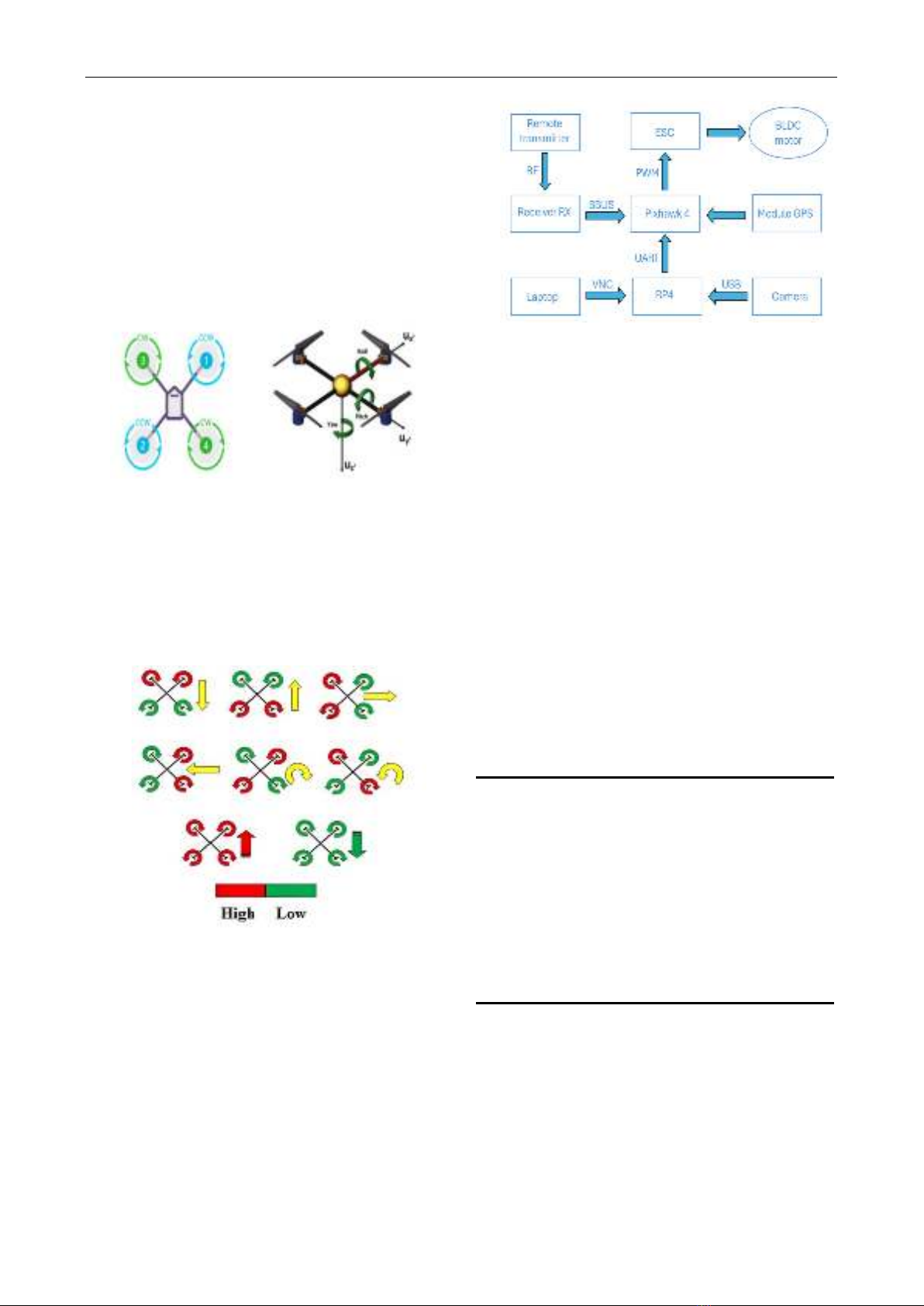
A. Principles of Quadcopter Flight
A quadcopter [4] is a type of unmanned aerial vehicle
(UAV) designed to be capable of flight based on the
principle of four motors. The quadcopter consists of four
motors connected to a frame at equal distances (typically in
an X-shaped configuration). Two motors rotate clockwise,
while the remaining 2 motors rotate counterclockwise. This
distribution helps create a balanced system and control
motion in the air to generate a specific thrust force to lift
the quadcopter into the air [9], as illustrated in Figure 1.
Figure 1. Propeller orientation, motion direction of the
Quadcopter
The direction of the aircraft during movement is
controlled by two motors, depending on the direction of
movement, these motors adjust their speed to create an
angle relative to the balance axis. The direction of
movement of the aircraft is indicated by the change in speed
of the motors.
Figure 2. Quadcopter flight principle
To make the aircraft move forward, motors 1 and 2 will
maintain or decrease speed while motors 3 and 4 will spin
faster. The same applies to other directions. The process of
controlling the direction of movement of the aircraft is
usually done through an autopilot system or through pilot
intervention. This system needs to be constantly considered
and adjusted to maintain stability and safety during flight.
B. Quadcopter structure
In this paper, the structure of the unmanned aerial
vehicle Quadcopter is displayed in Figure 3.
Figure 3. Block diagram of the Quadcopter model
The structure includes: Pixhawk 4 flight controller,
Raspberry Pi 4 embedded computer, camera, Electronic
Speed Controller (ESC), Signal receiver RX, (Brushless
DC Motors (BLDC), transmitter remote, Quad frame,
…The combination of Raspberry Pi 4 (RPI4) and Pixhawk
4 in the Quadcopter model is a unique integration that
provides high efficiency in the drone field [5]. Raspberry
Pi 4, a compact and powerful embedded computer, can run
image processing algorithms and collect environmental
data. Pixhawk 4, an autopilot flight controller, provides
precise and stable control for the drone. Pixhawk 4
integrates sensors and decoders to ensure high accuracy in
maintaining stability and navigation. This combination
creates a perfect system, where RPI4 handles complex
tasks such as image processing, data communication, while
Pixhawk 4 is responsible for flight control and data
collection from sensors.
Table 1 below presents the devices integrated into the
prototype design of the study, along with the corresponding
mass specifications of each device.
Table I. Weight of devices in Quadcopter
Device
Weight (gam)
Raspberry Pi4
63
Pixhawk 4
33
ESC 30A x4
168
Signal Receiver RX
18
GPS Module
33
Swivel base + Camera
45
Motor X2216 KV950 x4
280
Quadcopter Frame
480
Pine Lipo 3S 2300 mAh
180
Wire + other devices
60
Total weight
1360 gam
With the actual weight of the Quadcopter being 1360
grams, corresponding to a weight of 13.34 N (with the
gravitational acceleration g being 9.81m/s2), various flight
modes such as ascent (altitude changes), hovering and
acceleration will require a greater lift force. The
Quadcopter's four propellers are responsible for generating
both lift and thrust, so the lift force needs to be doubled to
ensure the performance of these tasks, totaling 26.68N
(also the value required to maintain stability when losing
control of flight). Based on the technical specifications and
the provided propeller data, the thrust generated by the four
(b) Motion direction
(a) Propeller orientation
SOÁ 01 (CS.01) 2024
TAÏP CHÍ KHOA HOÏC COÂNG NGHEÄ THOÂNG TIN VAØ TRUYEÀN THOÂNG 99
Thanh Han Trong, Nghia Cao Xuan, Hung Dinh Tan
propellers is 764 * 4 = 3056gf ≈ 29.98N, which is greater
than 26.68N. Therefore, it can be concluded that the
Quadcopter exceeds the required lift threshold to take off
into the air. With the given weight, the Quadcopter is fully
capable of withstanding wind, consuming less energy
compared to larger UAVs, thereby maintaining tracking
time and stability in rapidly changing environmental
conditions.
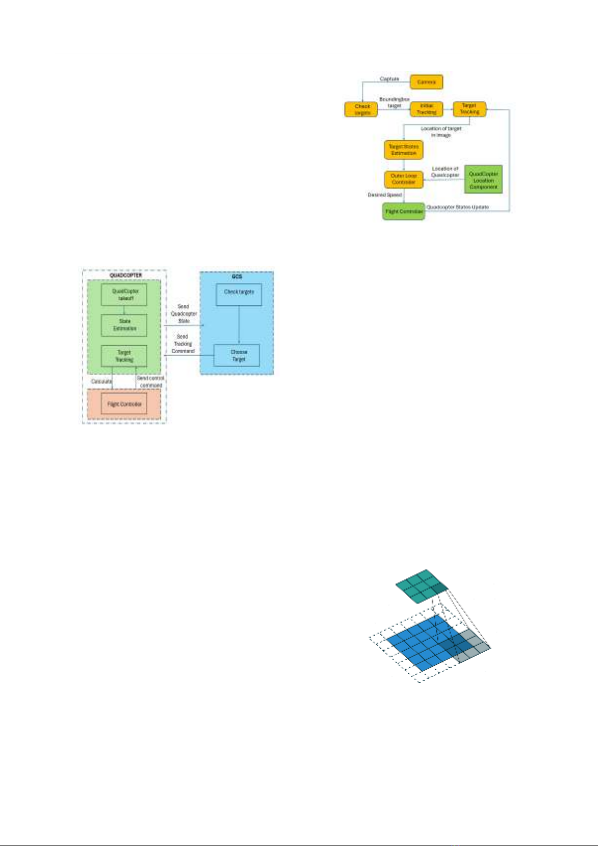
C. Overview of target tracking system
The target tracking system based on Computer Vision
comprises the UAV platform, the ground station platform,
tracking algorithms, target state estimation algorithms and
the UAV flight controller running on the Quadcopter
platform in real-time. The ground station platform serves
as the interface for monitoring the system's status and
sending instructions to the Quadcopter.
Figure 4. Operation diagram of target tracking function
After completing all pre-flight checks, the Quadcopter
will take off and send the current status to the ground
station. The ground station then enters target inspection
mode and can select targets for tracking. Once the target is
selected, the ground station sends a Track command to the
Quadcopter. At this time, the position and velocity of the
target are calculated by the flight controller to send control
commands to the Quadcopter to track the target.
D. Algorithm used in the article
1) Tracking algorithm
Tracking is the process of estimating the motion of an
object across successive frames, with the prerequisite that
the object's position is known from previous frames. In this
paper, the target is chosen based on user preference. After
the user selects the target to track, the Tracking algorithm
determines the position of the target in the frame (in pixel
coordinates). Next, the state estimation algorithm is used
to evaluate the local position and velocity of the target.
Additionally, the flight controller is designed to control the
speed and orientation of the Quadcopter accordingly based
on the obtained information. This system enables effective
target tracking and control of the Quadcopter's
performance as illustrated in Figure 5.
Figure 5. System operating process
Some lightweight tracking algorithms that can be used
on RPI4 to track targets include KCF [7], CSRT [8],
MOSSE [9]... However, in practical scenarios, objects
may be occluded or their colors may change rapidly due to
fast motion, causing the recognition algorithms to fail to
detect them. Therefore, in this paper, we propose a new
model combining the AKAZE [12] algorithm and Kalman
filter [13] to enhance the KCF algorithm [14]. The
AKAZE algorithm extracts feature points and the Kalman
filter predicts the next position of the object.
a) AKAZE Algorithm
AKAZE [12] (Accelerated-KAZE) is an algorithm
designed for rapid and efficient operation, particularly in
scenarios involving intricate and noisy images. It is an
accelerated version of the KAZE (KAZE Features)
algorithm, designed to provide high accuracy and scale
and position invariance features. With changes in scale and
position of the object, the features can still be recognized.
The operating principle of the AKAZE algorithm
involves constructing the Hessian matrix [16] and finding
the extreme points of the Hessian determinant to identify
the feature points in the image. By sliding successive
windows and comparing them with the current scale
window to find the pixels in each window and all its
neighboring pixels, the maximum value is the extreme
point. Once the position of the feature point (extreme point)
is found, accurate pixel localization will be performed.
Figure 6. Sliding window process to find the extreme point
In this paper, Haar wavelet functions [17] are used
based on the Wavelet transform, which helps analyze and
represent image information at different detail levels from
high-frequency details to low-frequency features, thereby
reducing noise and increasing computational efficiency.
SOÁ 01 (CS.01) 2024
TAÏP CHÍ KHOA HOÏC COÂNG NGHEÄ THOÂNG TIN VAØ TRUYEÀN THOÂNG 100
AUTONOMOUS TARGET TRACKING CONTROL METHOD FOR QUADROTORS USING ARTIFICIAL INTELLIGENCE
The Haar wavelet functions are defined by the following
functions.
𝜙(𝑥)= {1, 𝑥 ∈ [0,1)
0, 𝑒𝑙𝑠𝑒
(1)
𝜓(𝑥) = {1, 𝑥 ∈ [0, 1
2 )
−1, 𝑥 ∈ [1
2, 1 )
0 ,𝑒𝑙𝑠𝑒
(2)
In which the function 𝜙(x) is called the scaling function
and the function 𝜓(x) is called the mother Wavelet function
of the Haar wavelet functions. The family of basis functions
is defined by:
𝜓𝑘𝑗(𝑥)=
{
1, 𝑥 ∈ [ 𝑘
2𝑗 ,𝑘+0,5
2𝑗 ]
−1, 𝑥 ∈ [ 𝑘+0.5
2𝑗 ,𝑘+1
2𝑗 ]
0, 𝑒𝑙𝑠𝑒
(3)
With j being referred to as the dilation parameter and k
being referred to as the translation parameter.
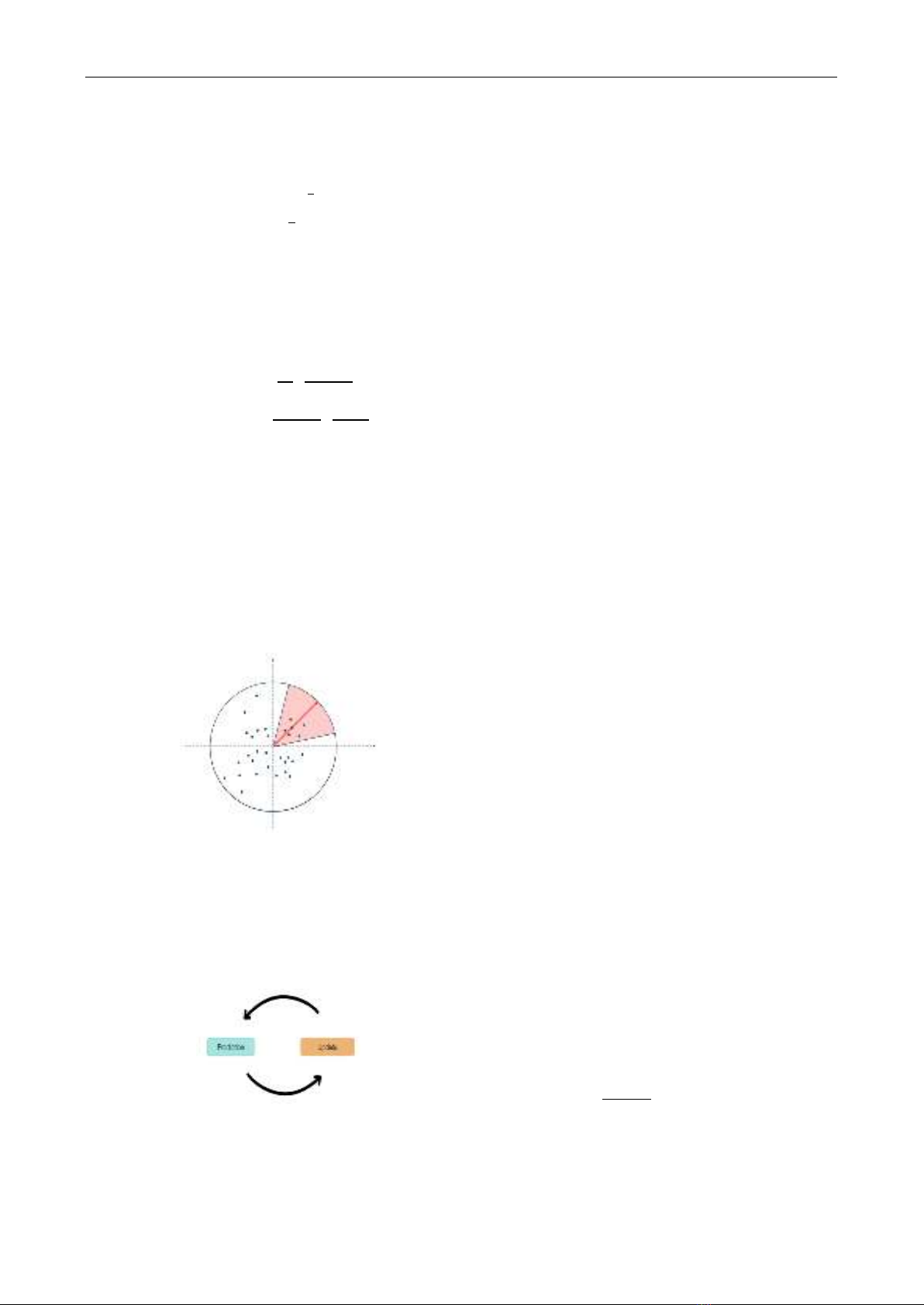
Assuming the scale parameter of the feature point is σ,
the search radius is set to 6σ. Create a circular region with
a radius of 6σ and then divide it into sections with 60° each,
forming a fan-shaped area. Next, rotate the fan-shaped area
and calculate the sum of the Haar wavelet features. The
direction with the largest sum of wavelet features will be
determined as the main direction ation parameter.
Figure 7. The sector scanning process to find the cardinal
direction
b) Kalman Filter
Using the Kalman filter [13], we can predict the future
state of the object by leveraging the iteration of two
prediction and update states.
Figure 8. Loop between prediction and update state
• Prediction State:
𝜙𝑥𝑘|𝑘−1= 𝐹𝑘.𝑥𝑘−1|𝑘−1
(4)
𝑃𝑘|𝑘−1= 𝐹𝑘𝑃𝑘−1|𝑘−1𝐹𝑘𝑇+ 𝑄𝑘
(5)
With 𝑥𝑘|𝑘−1,𝑥𝑘−1|𝑘−1 are the estimate of the system
state at time k before receiving measurement data and time
k-1 based on all previous measurement data, respectively.
𝐹𝑘 is the motion matrix, representing the transition of the
state from time k-1 to k. 𝑃𝑘|𝑘−1,,𝑃𝑘−1|𝑘−1 are the
covariance at time k and k-1, respectively. Qk is the noise
matrix.
• Update State:
In this step, the predicted state is corrected based on the
difference between the actual measurement results 𝑧𝑘 and
expected measurement results 𝑧𝑘 from the measurement
matrix H. Equation (6) represents the mathematical
expression of the measurement model.
𝑧𝑘=𝐻.𝑥𝑘
(6)
After obtaining the actual measurement results, the
difference 𝑦𝑘 between real measurement and model
measurement is calculated according to equation (7). The
complete calculation of this correction step is expressed
from equations (8), (9).
𝑦𝑘=𝑧𝑘− 𝑧𝑘
(7)
𝑥𝑘|𝑘= 𝑥𝑘|𝑘−1 + 𝐾𝑘𝑦𝑘
(8)
𝑃𝑘|𝑘=(𝐼− 𝐾𝑘𝐻𝑘)𝑃𝑘|𝑘−1
(9)
With 𝑥𝑘|𝑘 is an estimate of the system state at time k
after receiving the measurement data, 𝐾𝑘 is the Kalman
weight, 𝑃𝑘|𝑘covariance after receiving measurement data at
time. 𝐼,𝐻𝑘 are the unit matrix and measurement matrix,
respectively.
c) KCF tracker algorithm
KCF [14] (Kernelized Correlation Filter) tracker is a
popular method in object tracking in video, based on
kernelized correlation filters to predict the position of the
object in the next frames of the video . In correlation filter,
the correlation between two samples is taken and when
these samples match then the correlation value is highest.
In KCF, the algorithm operates in the frequency domain
using training samples captured by cyclic displacement of
image patches. These samples are used to train a classifier
in the frequency domain. The classifier's goal is to find the
optimal function that minimizes the squared error between
the samples and their regression targets. This function is
represented as f(z) = ωTz, where ω is the optimal coefficient
vector. min
𝜔∑(𝑓(𝑥𝑖)− 𝑦𝑖)2
𝑖+ 𝜆‖𝜔‖2 (10)
To solve for the classification coefficients α, the
problem is transformed using the Fourier transform and the
convolution theorem [18]. The coefficient α is obtained by
solving the equation:
𝐹(𝛼)= 𝐹(𝑦)
𝐹(𝑘𝑥)+ 𝜆 (11)
where F represents the Fourier transform [19], y is the
set of regression targets, and kx is the kernel distance
calculated using a Gaussian kernel K in the Fourier domain.
SOÁ 01 (CS.01) 2024
TAÏP CHÍ KHOA HOÏC COÂNG NGHEÄ THOÂNG TIN VAØ TRUYEÀN THOÂNG 101
Thanh Han Trong, Nghia Cao Xuan, Hung Dinh Tan
For an image patch z of size W × H in a new frame t +
1, where z is cropped in the search window around the
object location, the confidence response is calculated as
follows: 𝑦(𝑧)= 𝐹−1(𝐹(𝑘𝑧)⊙𝐹(𝛼)) (12)
Where ⊙ is the element product, kz =K(z, 𝑥𝑖) is the
kernel distance between the regression sample z and the
learned object shape 𝑥𝑖. The final target position is
determined by the location where the maximum response
R occurs, and the response R is calculated by R = max ŷ(z).
In this paper, AKAZE is used to extract features. The
feature matching process is carried out to find the similarity
between features from images based on their
characteristics. Once suitable matching features are found
with the previous features, the next step is to determine the
corresponding feature pairs between two images. Then, the
position of the moving object in the current frame is
determined, and the bounding box around the object is
computed. For cases where the number of matched points
is smaller than the threshold, the Kalman filter is used to
estimate the position and size of the object's bounding box.
Finally, the bounding box coordinates are used to update
the KCF tracker.
2) Flight attitude estimation algorithm
As previously described, the Tracking algorithm
provides the coordinates of the object's centroid to estimate
its state. These coordinates are represented as pixel
coordinates. The Quadcopter will adjust its flight state so
that these coordinates are shifted from the target
coordinates to the coordinates of the center of the camera
frame mounted on the Quadcopter.
Figure 9. Quadcopter moves according to object
coordinates
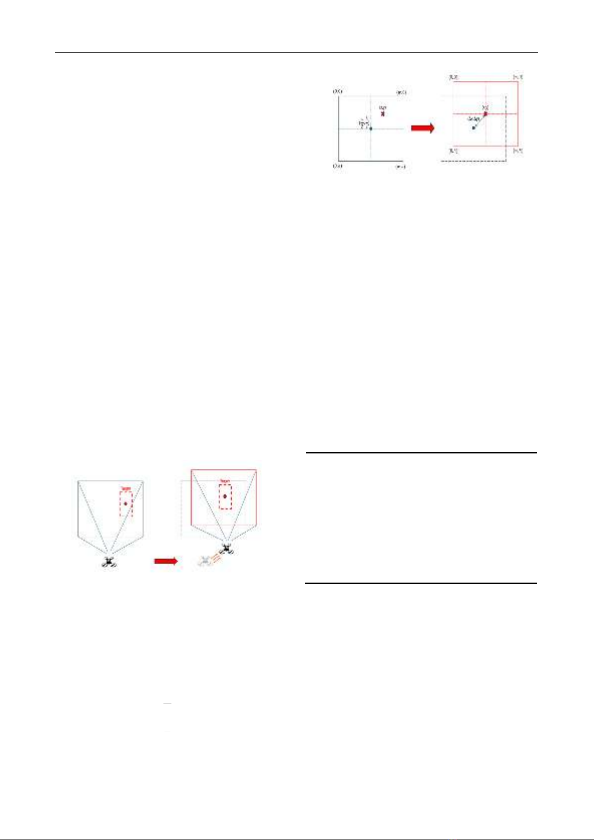
Assuming the target coordinates in pixels are (x, y) and
the coordinates of the center of the frame are (w/2, h/2)
where (w, h) is the resolution of the camera. Equations (13)
and (14) respectively represent the pixel deviation between
the target coordinates and the coordinates of the center of
the frame along the x-axis and the y-axis.
𝛥𝑥=𝑥− 𝑤
2
(13)
∆𝑦=𝑦− ℎ
2
(14)
Figure 10. Converting object coordinates to the center of
the frame
Once the change in coordinates (in pixel units) is
known, we can describe the relationship between the
change in target coordinates (pixels) and the change in
Quadcopter coordinates (in meters) using the following
expressions (15) and (16).
∆𝑥𝑞𝑢𝑎𝑑=𝑘.∆𝑥 (15)
∆𝑦𝑞𝑢𝑎𝑑 =𝑘.∆𝑦 (16)
With k representing the scale factor that reflects the
relationship between the measurement units on the image
and the real-world units in physical space.
By initializing a safe distance d (from d1 to d2 meter)
and a safe zone [x1:x2,y1:y2] (pixel), there will be shown
in Table 12. Table 2 describes the conditions set as shown
in the diagram above and the QuadCopter's movement
under those conditions.
Table II. Movement conditions for Quadcoper
No
Condition
Control
1
d > d2
Fly forward
2
d < d1
Fly backward
3
d1 < d < d2
Keep state
4
x > x2
Move right
5
x < x1
Move left
6
x1 < x < x2
Keep state
7
y > y2
Fly down
8
y > y1
Fly up
9
y1 < y < y2
Keep state
III. EXPERIMENT
A. Tracking Algorithm
The paper compares the performance of the Tracking
algorithm using AKAZE and Kalman to improve the KCF
algorithm with lightweight tracking algorithms that do not
require high hardware and are popular today such as KCF,
MOSSE, and CSRT. We use two evaluation parameters to
compare: FPS (Frame Per Second) and IoU (Intersection
over Union). FPS is measured by dividing one second by
the average processing time of one frame and IoU is
evaluated by calculating the agreement between the
bounding box predicted by the algorithm and the labeled
ground truth bounding box with an agreement ratio in the
range of 0.5 – 0.95. Table 3 presents the results of the
SOÁ 01 (CS.01) 2024
TAÏP CHÍ KHOA HOÏC COÂNG NGHEÄ THOÂNG TIN VAØ TRUYEÀN THOÂNG 102