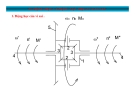
Ồ Ồ Ụ Ụ Ỉ Ỉ CÂN CH NH Đ NG TR C CÂN CH NH Đ NG TR C
Rotational center
Ồ Ồ Ụ Ụ Ỉ Ỉ CÂN CH NH Đ NG TR C CÂN CH NH Đ NG TR C
Colinearity
Ồ Ồ Ụ Ụ Ỉ Ỉ CÂN CH NH Đ NG TR C CÂN CH NH Đ NG TR C
Misalignment
Ồ Ồ Ụ Ụ Ỉ Ỉ CÂN CH NH Đ NG TR C CÂN CH NH Đ NG TR C
Stationary and movable machine
Ồ Ồ Ụ Ụ Ỉ Ỉ CÂN CH NH Đ NG TR C CÂN CH NH Đ NG TR C
Horizontal Misalignment Horizontal Misalignment
Ồ Ồ Ụ Ụ Ỉ Ỉ CÂN CH NH Đ NG TR C CÂN CH NH Đ NG TR C
Vertical Misalignment Vertical Misalignment
Ồ Ồ Ụ Ụ Ỉ Ỉ CÂN CH NH Đ NG TR C CÂN CH NH Đ NG TR C
Types of misalignment Types of misalignment
Ồ Ồ Ụ Ụ Ỉ Ỉ CÂN CH NH Đ NG TR C CÂN CH NH Đ NG TR C
Offset misalignment
Ồ Ồ Ụ Ụ Ỉ Ỉ CÂN CH NH Đ NG TR C CÂN CH NH Đ NG TR C
Types of misalignment Types of misalignment
Angular misalignment
Alignment methods Alignment methods
Alignment methods. Alignment methods.
Ồ Ồ Ụ Ụ Ỉ Ỉ CÂN CH NH Đ NG TR C CÂN CH NH Đ NG TR C
Alignment methods.
Straight edges , Rim and face , Reversed dial , Laser
Rimface method Rimface method
Ồ Ồ Ụ Ụ Ỉ Ỉ CÂN CH NH Đ NG TR C CÂN CH NH Đ NG TR C
Ồ Ồ Ụ Ụ Ỉ Ỉ CÂN CH NH Đ NG TR C CÂN CH NH Đ NG TR C
Why is shaft alignment so important?
Misalignment creates forces in the coupling
Ồ Ồ Ụ Ụ Ỉ Ỉ CÂN CH NH Đ NG TR C CÂN CH NH Đ NG TR C
Why is shaft alignment so important?
Vibrations Vibrations
Ồ Ồ Ụ Ụ Ỉ Ỉ CÂN CH NH Đ NG TR C CÂN CH NH Đ NG TR C
Bearing wear.
Ồ Ồ Ụ Ụ Ỉ Ỉ CÂN CH NH Đ NG TR C CÂN CH NH Đ NG TR C
Bearing life equation.
Ồ Ồ Ụ Ụ Ỉ Ỉ CÂN CH NH Đ NG TR C CÂN CH NH Đ NG TR C
Misaligned seals causes leakage.
Ồ Ồ Ụ Ụ Ỉ Ỉ CÂN CH NH Đ NG TR C CÂN CH NH Đ NG TR C
The dial indicator.
Ồ Ồ Ụ Ụ Ỉ Ỉ CÂN CH NH Đ NG TR C CÂN CH NH Đ NG TR C
RimFace Alignment Method RimFace Alignment Method
Ồ Ồ Ụ Ụ Ỉ Ỉ CÂN CH NH Đ NG TR C CÂN CH NH Đ NG TR C
Uncoupled shafts.
RimFace Dimensions RimFace Dimensions
Ồ Ồ Ụ Ụ Ỉ Ỉ CÂN CH NH Đ NG TR C CÂN CH NH Đ NG TR C
Ồ Ồ Ụ Ụ Ỉ Ỉ CÂN CH NH Đ NG TR C CÂN CH NH Đ NG TR C
I. Measuring Vertical Misalignment I. Measuring Vertical Misalignment
1. Rotate the dial indicators to 6:00.
2. Set the rim dial indicator to the sag value. 3. Setting the sag value NOTE: For example, if the amount of sag for the rim dial fixture is determined to be 9 mils, the dial would be set to read 9 at the 6:00 position.
Ồ Ồ Ụ Ụ Ỉ Ỉ CÂN CH NH Đ NG TR C CÂN CH NH Đ NG TR C
4. Rotate both shafts (if possible) to 12:00. 4. Rotate both shafts (if possible) to 12:00.
5. Record the DIR and DIF dial indicator TIR values.
(TIR Total indicator readings)
Interpreting Vertical Misalignment Data Interpreting Vertical Misalignment Data To determine offset and angularity from the 12:00 TIR’s, use To determine offset and angularity from the 12:00 TIR’s, use the following rules: the following rules: Coupling Offset =
Shaft Angularity =
Rim Dial (DIR) TIR Coupling Offset = Rim Dial (DIR) TIR 2 2 Face Dial (DIF) TIR Shaft Angularity = Face Dial (DIF) TIR A dimension A dimension
Consider the following RimFace 12:00 total indicator Consider the following RimFace 12:00 total indicator readings (TIR’s). readings (TIR’s).
Ồ Ồ Ụ Ụ Ỉ Ỉ CÂN CH NH Đ NG TR C CÂN CH NH Đ NG TR C
1. The Rim Dial TIR is 34 mils (0.864 mm). The coupling offset is
17 mils (0.432 mm), or 17 mils low.
2. The Face Dial TIR is +24 mils (+0.610 mm). Given an A dimension of 4 inches (101.6 mm), the vertical angularity would be +24 mils/4” (0.006 mm/mm) = 6.0 mils per inch (0.6 mm / 100 mm).
Ồ Ồ Ụ Ụ Ỉ Ỉ CÂN CH NH Đ NG TR C CÂN CH NH Đ NG TR C
Ồ Ồ Ụ Ụ Ỉ Ỉ CÂN CH NH Đ NG TR C CÂN CH NH Đ NG TR C
II. Measuring Horizontal Misalignment II. Measuring Horizontal Misalignment
1. To measure horizontal misalignment, perform the following steps: 1. To measure horizontal misalignment, perform the following steps: 2. Rotate the dial indicators to 9:00. 2. Rotate the dial indicators to 9:00.
Measuring horizontal misalignment, 9 o’clock Measuring horizontal misalignment, 9 o’clock
3. Set both dial indicators to zero. 3. Set both dial indicators to zero. 4. Rotate both shafts to 3:00. 4. Rotate both shafts to 3:00.
Ồ Ồ Ụ Ụ Ỉ Ỉ CÂN CH NH Đ NG TR C CÂN CH NH Đ NG TR C
Ồ Ồ Ụ Ụ Ỉ Ỉ CÂN CH NH Đ NG TR C CÂN CH NH Đ NG TR C
Horizontal misalignment, 3 o’clock.
5. Record the DIF and DIR dial indicator TIR values.
Interpreting Horizontal Misalignment Data Interpreting Horizontal Misalignment Data
To determine offset and angularity from the 3:00 TIR’s, use the following To determine offset and angularity from the 3:00 TIR’s, use the following rules: rules: Coupling Offset =
Shaft Angularity =
Coupling Offset = Rim Dial (DIR) TIR Rim Dial (DIR) TIR 2 2 Shaft Angularity = Face Dial (DIF) TIR x 100 = mm / 100 mm Face Dial (DIF) TIR x 100 = mm / 100 mm A dimension A dimension
Consider the following RimFace 3:00 total indicator readings (TIR’s). Consider the following RimFace 3:00 total indicator readings (TIR’s).
Ồ Ồ Ụ Ụ Ỉ Ỉ CÂN CH NH Đ NG TR C CÂN CH NH Đ NG TR C
Example, horizontal TIR readings.
1. The Rim Dial TIR is +16 mils (+0.406 mm). The coupling offset is +8 mils
(+0.203 mm), or 8 mils to the right.
2. The Face Dial TIR is 16 mils (0.406 mm). Given an A dimension of 4
inches (101.6 mm), the horizontal angularity would be 16 mils/4” (0.004 mm/mm) = 4.0 mils per inch (0.4 mm/ 100mm).
Ồ Ồ Ụ Ụ Ỉ Ỉ CÂN CH NH Đ NG TR C CÂN CH NH Đ NG TR C
Ồ Ồ Ụ Ụ Ỉ Ỉ CÂN CH NH Đ NG TR C CÂN CH NH Đ NG TR C
Ồ Ồ Ụ Ụ Ỉ Ỉ CÂN CH NH Đ NG TR C CÂN CH NH Đ NG TR C
Ồ Ồ Ụ Ụ Ỉ Ỉ CÂN CH NH Đ NG TR C CÂN CH NH Đ NG TR C
Ồ Ồ Ụ Ụ Ỉ Ỉ CÂN CH NH Đ NG TR C CÂN CH NH Đ NG TR C
Ồ Ồ Ụ Ụ Ỉ Ỉ CÂN CH NH Đ NG TR C CÂN CH NH Đ NG TR C
Ồ Ồ Ụ Ụ Ỉ Ỉ CÂN CH NH Đ NG TR C CÂN CH NH Đ NG TR C
Ồ Ồ Ụ Ụ Ỉ Ỉ CÂN CH NH Đ NG TR C CÂN CH NH Đ NG TR C
Ồ Ồ Ụ Ụ Ỉ Ỉ CÂN CH NH Đ NG TR C CÂN CH NH Đ NG TR C


![Chương trình Test Aero-Acoustic: Tổng hợp [Mới nhất]](https://cdn.tailieu.vn/images/document/thumbnail/2012/20120202/luly_meo1/135x160/aero_acoustic_test_programs_split_6_4917.jpg)


![Cẩm nang Gia công kim loại Việt Nam [mới nhất]](https://cdn.tailieu.vn/images/document/thumbnail/2026/20260513/baobinh_011/135x160/7971778670576.jpg)


![Giáo trình Hàn ống nâng cao (Nghề Hàn - CĐ) Trường Cao đẳng nghề Hải Dương [Mới nhất]](https://cdn.tailieu.vn/images/document/thumbnail/2025/20251212/laphong0906/135x160/47521779076565.jpg)


%20--%3e%3cdefs%3e%3cstyle%3e%20.st0%20{%20fill:%20%23fff;%20}%20.st1%20{%20fill:%20%237800fa;%20}%20%3c/style%3e%3c/defs%3e%3cpath%20class='st1'%20d='M117.78,12.18H43.11c2.9,3.47,4.65,7.94,4.65,12.82,0,5.6-2.3,10.66-6.01,14.29h76.02l7.22-13.56-7.22-13.56Z'/%3e%3cg%3e%3cpath%20class='st0'%20d='M53.58,26.17h-.59v-1.46h.59v-4.96h2.83c1.78,0,2.67.94,2.67,2.82v5.76c0,1.87-.89,2.81-2.67,2.81h-2.83v-4.96ZM55.36,21.37v3.34h1.1v1.46h-1.1v3.34h1.01c.61,0,.91-.37.91-1.1v-5.93c0-.74-.3-1.1-.91-1.1h-1.01Z'/%3e%3cpath%20class='st0'%20d='M65.99,31.14h-1.8l-.31-2.07h-2.19l-.31,2.07h-1.64l1.82-11.39h2.62l1.82,11.39ZM65.28,18.04c-.25.46-.51.77-.75.94-.21.15-.47.22-.79.22-.26,0-.57-.07-.92-.22l-.38-.15c-.14-.05-.26-.07-.37-.07-.3,0-.53.18-.71.54l-.91-.68c.25-.46.51-.77.75-.94.21-.14.48-.21.79-.21.26,0,.57.07.92.21l.38.15c.14.05.26.07.37.07.3,0,.53-.18.71-.54l.91.68ZM61.91,27.52h1.73l-.87-5.76-.87,5.76Z'/%3e%3cpath%20class='st0'%20d='M74.53,26.89v1.52c0,1.91-.89,2.86-2.67,2.86s-2.67-.95-2.67-2.86v-5.93c0-1.91.89-2.86,2.67-2.86s2.67.95,2.67,2.86v1.11h-1.69v-1.22c0-.75-.31-1.12-.93-1.12s-.93.37-.93,1.12v6.15c0,.74.31,1.11.93,1.11s.93-.37.93-1.11v-1.63h1.69Z'/%3e%3cpath%20class='st0'%20d='M81.4,31.14h-1.8l-.31-2.07h-2.19l-.31,2.07h-1.64l1.82-11.39h2.62l1.82,11.39ZM75.9,19.2l1.52-1.91h1.71l1.51,1.91h-1.61l-.76-.95-.75.95h-1.61ZM77.32,27.52h1.73l-.87-5.76-.87,5.76ZM83.1,15.99l-1.76,1.91h-1.26l1.17-1.91h1.86Z'/%3e%3cpath%20class='st0'%20d='M84.86,19.75c1.78,0,2.67.94,2.67,2.82v1.48c0,1.87-.89,2.81-2.67,2.81h-.85v4.28h-1.79v-11.39h2.64ZM84.01,21.37v3.86h.85c.58,0,.87-.36.87-1.08v-1.71c0-.71-.29-1.07-.87-1.07h-.85Z'/%3e%3cpath%20class='st0'%20d='M93.51,19.75c1.78,0,2.67.94,2.67,2.82v1.48c0,1.87-.89,2.81-2.67,2.81h-.85v4.28h-1.79v-11.39h2.64ZM92.66,21.37v3.86h.85c.58,0,.87-.36.87-1.08v-1.71c0-.71-.29-1.07-.87-1.07h-.85Z'/%3e%3cpath%20class='st0'%20d='M98.8,31.14h-1.79v-11.39h1.79v4.88h2.03v-4.88h1.83v11.39h-1.83v-4.88h-2.03v4.88Z'/%3e%3cpath%20class='st0'%20d='M105.36,24.55h2.46v1.62h-2.46v3.34h3.09v1.63h-4.88v-11.39h4.88v1.63h-3.09v3.18ZM108.17,17.29l-1.76,1.91h-1.26l1.17-1.91h1.86Z'/%3e%3cpath%20class='st0'%20d='M112.2,19.75c1.78,0,2.67.94,2.67,2.82v1.48c0,1.87-.89,2.81-2.67,2.81h-.85v4.28h-1.79v-11.39h2.64ZM111.35,21.37v3.86h.85c.58,0,.87-.36.87-1.08v-1.71c0-.71-.29-1.07-.87-1.07h-.85Z'/%3e%3c/g%3e%3ccircle%20class='st1'%20cx='25'%20cy='25'%20r='20'/%3e%3cpath%20class='st0'%20d='M32.78,19.27c2.92,0,4.43,2.55,5.28,5.33l.71,2.17c.14.38-.33.75-.71.75h-5.61c.19-.33.24-.71.09-1.08l-.75-2.45c-.43-1.32-.99-2.64-1.79-3.77.75-.57,1.65-.94,2.78-.94h0ZM25,18.38c3.25,0,4.9,2.78,5.89,5.89l.76,2.45c.14.42-.33.8-.8.8h-11.69c-.42,0-.94-.38-.8-.8l.75-2.45c.99-3.11,2.64-5.89,5.89-5.89h0ZM25,11.35c1.74,0,3.11,1.37,3.11,3.11s-1.37,3.11-3.11,3.11-3.11-1.41-3.11-3.11,1.41-3.11,3.11-3.11h0ZM17.27,19.27c1.08,0,1.98.38,2.73.94-.8,1.13-1.37,2.45-1.74,3.77l-.8,2.45c-.14.38-.05.75.09,1.08h-5.56c-.42,0-.9-.38-.75-.75l.71-2.17c.9-2.78,2.41-5.33,5.33-5.33h0ZM17.27,12.91c1.51,0,2.78,1.27,2.78,2.83s-1.27,2.83-2.78,2.83-2.83-1.27-2.83-2.83,1.27-2.83,2.83-2.83h0ZM32.78,12.91c1.56,0,2.78,1.27,2.78,2.83s-1.23,2.83-2.78,2.83-2.83-1.27-2.83-2.83,1.27-2.83,2.83-2.83h0ZM27.07,28.56v.09c0,.57-.24,1.08-.61,1.46h0v.05c-.38.33-.9.57-1.46.57s-1.08-.24-1.46-.61h0c-.38-.38-.61-.9-.61-1.46v-.09h1.41v.09c0,.19.05.38.19.47v.05c.09.09.28.19.47.19s.38-.09.47-.19v-.05c.14-.09.24-.28.24-.47t-.05-.09h1.41ZM30.99,28.56v.09c0,1.65-.66,3.16-1.74,4.24-1.08,1.08-2.59,1.79-4.24,1.79s-3.16-.71-4.24-1.79l-.05-.05c-1.04-1.08-1.7-2.55-1.7-4.2v-.09h1.41v.09c0,1.27.47,2.4,1.27,3.25h.05c.85.85,1.98,1.37,3.25,1.37s2.4-.52,3.25-1.37c.85-.8,1.37-1.98,1.37-3.25v-.09h1.37ZM34.99,28.56v.09c0,2.78-1.13,5.28-2.92,7.07-1.79,1.79-4.29,2.92-7.07,2.92s-5.23-1.13-7.07-2.92c-1.79-1.79-2.92-4.29-2.92-7.07v-.09h1.41v.09c0,2.4.94,4.53,2.5,6.08,1.56,1.56,3.72,2.5,6.08,2.5s4.52-.94,6.08-2.5c1.56-1.56,2.5-3.68,2.5-6.08v-.09h1.41Z'/%3e%3c/svg%3e)