Hindawi Publishing Corporation
EURASIP Journal on Advances in Signal Processing
Volume 2007, Article ID 48406, 12 pages
doi:10.1155/2007/48406
Research Article
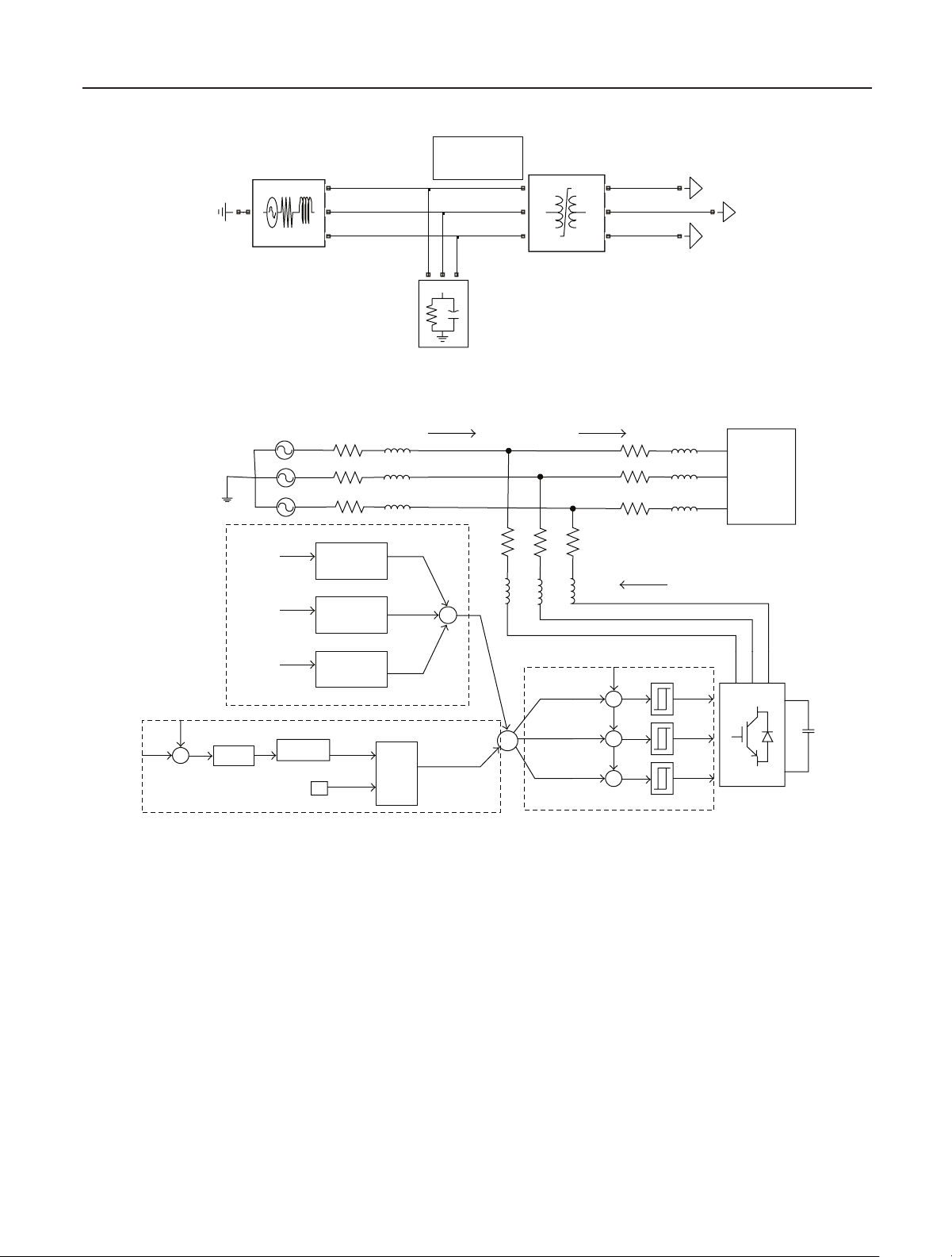
Prony Analysis for Power System Transient Harmonics
Li Qi, Lewei Qian, Stephen Woodruff, and David Cartes
The Center for Advanced Power Systems, Florida State University, Tallahassee, FL 32310, USA
Received 9 August 2006; Revised 15 December 2006; Accepted 18 December 2006
Recommended by Irene Y. H. Gu
Proliferation of nonlinear loads in power systems has increased harmonic pollution and deteriorated power quality. Not required
to have prior knowledge of existing harmonics, Prony analysis detects frequencies, magnitudes, phases, and especially damping
factors of exponential decaying or growing transient harmonics. In this paper, Prony analysis is implemented to supervise power
system transient harmonics, or time-varying harmonics. Further, to improve power quality when transient harmonics appear,
the dominant harmonics identified from Prony analysis are used as the harmonic reference for harmonic selective active filters.
Simulation results of two test systems during transformer energizing and induction motor starting confirm the eectiveness of the
Prony analysis in supervising and canceling power system transient harmonics.
Copyright © 2007 Li Qi et al. This is an open access article distributed under the Creative Commons Attribution License, which
permits unrestricted use, distribution, and reproduction in any medium, provided the original work is properly cited.
1. INTRODUCTION
In today’s power systems, the proliferation of nonlinear loads
has increased harmonic pollution. Harmonics cause many
problems in connected power systems, such as reactive power
burden and low system eciency. Harmonic supervision is
highly valuable in relieving these problems in power trans-
mission systems. Further, shunt active filters can be con-
nected in power distribution systems to improve power qual-
ity. With the compensating currents injected by the active
filters, the currents are cleaner and less harmonic pollution
induced by the nonlinear load aects the operation of the
connected power grid.
Normally, Fourier transform-based approaches are used
for supervising power system harmonics. In order to main-
tain the computational accuracy of Fourier transform, the
stationary and periodic characteristics of signals are gener-
ally required. However, power system loads, especially indus-
trial loads, are often dynamic in nature, and produce time
varying currents. In this paper, harmonics with time vary-
ing magnitudes in power systems are called power system
transient harmonics. The accuracy of Fourier transform is
aected when these transient or time varying harmonics ex-
ist. To achieve controllable harmonic cancellation for power
quality improvement, low filter ratings, and bandwidth re-
quirement reductions, harmonic selective active filters are
used in power distribution systems. Accurate harmonic ref-
erence generation of the harmonics is the key to these har-
monic selective active filters. Some of the harmonic refer-
ence generation methods require PLL (phase locked loops)
or frequency estimators for identifying the specific harmonic
frequency before the corresponding reference is generated
[14].
In this paper, Prony analysis is applied as an analysis
method for harmonic supervisors and as a harmonic ref-
erence generation method for harmonic selective active fil-
ters. Prony analysis, as an autoregressive spectrum analy-
sis method, has some valuable features. Prony analysis does
not require frequency information prior to filtering. Addi-
tional PLL or frequency estimators described earlier in ex-
isting active filters are no longer necessary. Prony-analysis-
based harmonic supervisors and active filters are thus ap-
plicable in situations where there is no prior knowledge of
the frequencies. Due to the ability to identify the damping
factors of transients, Prony analysis can accurately identify
growing or decaying components of signals. Transient har-
monics thus can be correctly identified from Prony analysis
for the Prony-based harmonic supervision and the harmonic
reference generation.
Some results in Prony analysis for supervising and can-
celing power system transient harmonics are presented in
this paper. Two important operations in power transmission
and distribution systems, energizing a transformer and start-
ing of an induction motor, induce transient harmonics and
have adverse eects on power system quality [57]. With an
appropriate Prony algorithm selected, nonstationary or time
2 EURASIP Journal on Advances in Signal Processing
varying transient harmonics during transformer energizing
and motor starting are identified. The harmonic results from
Prony analysis and Fourier transform are compared. The ef-
fectiveness of the Prony-based harmonic selective active fil-
ter is verified by simulation results. The advantages and dis-
advantages of the application of Prony analysis in harmonic
supervisors and active filters are also discussed.
In Section 2 of this paper, Prony analysis, including the-
ory basis, selection of Prony algorithm, tuning Prony param-
eters, and comparison of Prony analysis and Fourier Trans-
form, is described. In Section 3, two test systems, which re-
spectively represent a part of a transmission system and a dis-
tribution system, to study power system transient harmonics
are described. In Section 4, case studies using Prony-based
harmonic supervisors and harmonic selective active filters
are presented. In Section 5, some conclusions are drawn.
2. PRONY ANALYSIS
Since Prony analysis was first introduced into power system
applications in 1990, it has been widely used for power sys-
tem transient studies [8,9], but rarely used for power quality
studies. In this section, the basis for Prony analysis is pre-
sented. Then, the selection of an appropriate Prony algo-
rithm from three existing algorithms is discussed. A general
guidance of tuning Prony analysis parameters is given. At last,
Prony and Fourier analyses are compared.
2.1. Basis of Prony analysis
Prony analysis is a method of fitting a linear combination of
exponential terms to a signal as shown in (1)[10]. Each term
in (1) has four elements: the magnitude An, the damping fac-
tor σn, the frequency fn, and the phase angle θn.Eachexpo-
nential component with a dierent frequency is viewed as a
unique mode of the original signal y(t). The four elements
of each mode can be identified from the state space represen-
tation of an equally sampled data record. The time interval
between each sample is T:
y(t)=
N
n=1
Aneσntcos 2πf
nt+θn,n=1, 2, 3, ...,N. (1)
Using Euler’s theorem and letting t=MT, the samples of
y(t) are rewritten as (2)
yM=
N
n=1
BnλM
n,(2)
Bn=An
2en,(3)
λn=e(σn+j2πf
n)T.(4)
Prony analysis consists of three steps. In the first step, the
coecients of a linear predication model are calculated. The
linear predication model (LPM) of order N, shown in (5), is
built to fit the equally sampled data record y(t)withlength
M. Normally, the length Mshould be at least three times
larger than the order N:
yM=a1yM1+a2yM2+···+aNyMN.(5)
Estimation of the LPM coecients anis crucial for the
derivation of the frequency, damping, magnitude, and phase
angle of a signal. To estimate these coecients accurately,
many algorithms can be used. A matrix representation of the
signal at various sample times can be formed by sequentially
writing the linear prediction of yMrepetitively. By inverting
the matrix representation, the linear coecients ancan be
derived from (6). An algorithm, which uses singular value
decomposition for the matrix inversion to derive the LPM
coecients, is called SVD algorithm,
yN
yN+1
.
.
.
yM1
=
yN1yN2··· y0
yNyN1··· y1
.
.
..
.
..
.
..
.
.
yM2yM3··· yMN1
a1
a2
.
.
.
aN
.(6)
In the second step, the roots λnof the characteristic poly-
nomial shown as (7) associated with the LPM from the first
step are derived. The damping factor σnand frequency fnare
calculated from the root λnaccording to (4):
λNa1λN1··· aN1λaN
=λλ1λλ2···λλn···λλN.(7)
In the last step, the magnitudes and the phase angles of
the signal are solved in the least square sense. According to
(2), (8) is built using the solved roots λn:
Y=φB,(8)
Y=y0y1··· yM1T,(9)
φ=
11··· 1
λ1λ2··· λN
.
.
..
.
..
.
..
.
.
λM1
1λM1
2··· λM1
N
, (10)
B=B1B2··· BNT.(11)
The magnitude Anand phase angle θnare thus calculated
from the variables Bnaccording to (3).
The greatest advantage of Prony analysis is its ability to
identify the damping factor of each mode in the signal. Due
to this advantage, transient harmonics can be identified ac-
curately.
2.2. Selection of Prony analysis algorithm
Three normally used algorithms to derive the LPM coe-
cients, the Burg algorithm, the Marple algorithm, and the
SVD (singular value decomposition) algorithm [1113], are
compared for implementing Prony analysis in transient har-
monic studies. Basically, the three algorithms use dier-
ent objective functions to estimate LPM coecients. In our
Li Qi et al. 3
Table 1: Estimated dominant harmonics (EDH) on a nonstationary
signal.
EDH Ideal Burg Marple SVD
Frequencies (Hz)
#1 60 60.1690 59.9986 59.9987
#2 300 298.2309 279.3917 299.9951
#3 420 419.3031 420.0081 420.0138
#4 660 657.8118 659.9380 659.9578
#5 780 779.1504 779.9914 780.0137
Damping factors (s1)
#1 0 0.0037 0.0027 0.0012
#2 61.3173 0.2127 6.0403
#3 40.0940 0.1245 4.0638
#4 0 0.5625 0.1881 0.1097
#5 0 3.4003 0.6494 0.1752
Magnitudes (A)
#1 1 1.0001 0.9997 1.0002
#2 0.2 0.1478 0.1441 0.2002
#3 0.1 0.0819 0.0809 0.1003
#4 0.02 0.0184 0.0203 0.0204
#5 0.01 0.0104 0.0107 0.0103
Phase angles (degree)
#1 0 3.1693 0.0320 3.1693
#2 45 79.0299 44.9906 45.0567
#3 30 41.4376 30.2150 29.9158
#4 0 36.8397 0.8574 0.7913
#5 0 12.7567 0.1850 0.3631
study, the recursive Burg and Marple algorithms were pro-
grammed in Matlab according to the description by Kay and
Marple [13], while the nonrecursive SVD algorithm utilized
the Matlab pseudoinverse function pinv. This pinv function
uses LAPACK routines to compute the singular value decom-
position for the matrix inversion [14].
To choose the appropriate algorithm, the three algo-
rithms are applied on the same signals with the same Prony
analysis parameters. The signals are synthesized in the form
of (1) plus a noise to approximate real transient signals. The
synthesized signal includes time varying harmonics. No sud-
den change occurs in the signal. The eventual variation of
these harmonics with time can be described or modeled with
exponential functions. The noise level is much smaller com-
pared to the least harmonic component in the synthesized
signal, which can be achieved by appropriately preprocess-
ing technique. The sampling frequency is selected equal to
four times of the highest harmonic and the length of data
is six times of one cycle of the lowest harmonic [15]. The
algorithm with the best overall performance on identifying
frequency, damping factor, magnitude, and phase angle is se-
lected as the appropriate algorithm.
Table 1 lists the estimation results from the three algo-
rithms on one transient signal. More estimation results on
synthesized power system signals were derived by the au-
thors for dierent studies [16]. The dominant harmonics, in-
cluding the fundamental (60 Hz), the fifth, seventh, eleventh,
and thirteenth harmonics, are identified. From the table, the
damping factors from the SVD algorithm are much closer to
the ideal damping factors than those from the Marple and
the Burg algorithms. Additionally, the frequency, magnitude,
and phase angles from the SVD algorithm are more precise.
From comparison on the estimation results of various signals
to approximate power system transient harmonics, the SVD
algorithm has the best overall performance on all estimation
results and thus is selected as the appropriate algorithm for
our study.
2.3. Tuning of Prony analysis parameters
Since the estimation of data is an ill-conditioned problem
[12,13], one algorithm could perform completely dierently
on dierent signals. Therefore, Prony analysis parameters
should be adjusted by trial and error to achieve most accu-
rate results at dierent situations. Although the parameter
tuning is a trial and error process, there are still some rules to
follow. A general guidance on parameter adjustment is given
in the rest of this section.
A technique of shifting time windows by Hauer et al. [8]
is adopted for continuously detecting dominant harmonics
in a Prony-analysis-based harmonic supervisor. The shifting
time window for Prony analysis has to be filled with sampled
data before correct estimation results are derived. The selec-
tion of the equal sampling intervals between samples and the
data length in an analysis window depends on the simula-
tion time step and the estimated frequency range. The equal
sampling frequency follows Nyquist sampling theorem and
should be at least two times of the highest frequency in a sig-
nal. Since the Prony analysis results are not accurate for too
high sampling frequency [15], two or three times of the high-
est frequency is considered to produce accurate Prony analy-
sis results and was used in our study. Similarly, the length of
Prony analysis window should not be too long or too short
[15]. The length of the Prony analysis window should be at
least one and half times of one cycle of the lowest frequency
of a signal.
Besides the sampling frequency and the length of Prony
analysis window, the LPM order is another important Prony
analysis parameter. A common principle is that the LPM or-
der should be no more than one thirds of the data length
[8,15]. The data length and LPM order could be increased
together in order to accommodate more modes in simulated
signals. It is quite dicult to make the first selection of the
LPM order since the exact number of modes of a real system
is hard to determine. In our study, a guess of 14 is a good
start. If the order is found not high enough, the data length
of the Prony analysis window should be increased in order to
increase the LPM order.
The general guidance for tuning Prony analysis parame-
ters is applicable to other applications of Prony analysis. Not
requiring specific frequency of a signal for Prony analysis, the
tuning method is not sensitive to fine details of the signal and
thus extensive retuning for dierent types of transients in the
same system is unlikely to be necessary for Prony analysis.
2.4. Prony analysis and Fourier transform
As described earlier, Prony analysis can accurately analyze ex-
ponential signals. In power systems, the Fourier transform is
4 EURASIP Journal on Advances in Signal Processing
widely used for spectrum analysis. However, signals must be
stationary and periodic for the finite Fourier transform to be
valid.
The following analysis explains why results from the
Fourier transform are inaccurate for exponential signals. The
general form of a nonstationary signal can be found in (1). If
the phase angle of the signal is equal to zero, and the magni-
tude is equal to unity, then the general form can be simplified
into the signal shown in (12). The initial time of the Fourier
analysis is taken to be t0and the duration of the Fourier anal-
ysis window is T, which is equal to the period of the analysis
signal for accurate spectrum analysis:
x(t)=eσt cos(2πft).(12)
The Fourier transform during t0to t0+Tis calculated as
(13). The first term on the right-hand side of (13)isequal
to zero according to (14). Therefore, the magnitude of the
signal in terms of the Fourier transform is given in (15). The
ratio kbetween the magnitude of the Fourier transform in
(15) and the actual magnitude eδt0is shown as (16), which
indicates the average eect of the Fourier analysis window:
an=2A
Tt0+T
t0
eδt cos(2πft)cos(2πft)dt
=A
Tt0+T
t0
eδtcos(4πft)+1
dt
=A
Tt0+T
t0
eδt cos(4πft)dt +A
Tt0+T
t0
eδtdt,
(13)
1
Tt0+T
t0
eδt cos(4πft)dt
=1
T
eδt
δ2+(4π/T)2δcos(4πft)
+4πf sin(4πft)
t0+T
t0
=0,
(14)
an=1
Tt0+T
t0
eδtdt =1
δT eδt
t0+T
t0
=1
δT eδ(t0+T)eδ(t0)=eδt0eδT 1
δT ,
(15)
k=eδT 1
δT .(16)
Let us consider a fast damping signal and a slow damp-
ing signal with damping factors δequal to 100 and 0.01,
respectively. If the frequency fis equal to 60 Hz, then the
duration Tis equal to 0.0167 seconds. According to (16), the
ratio kbetween the Fourier magnitude and the real magni-
tude is derived as 0.4861 and 0.9999. If the damping factor is
equal to zero or the signal is nonexponential, the ration kbe-
comes one and the Fourier magnitude exactly reflects the real
signal magnitude. Therefore, with rapid decaying factors, the
magnitude derived from Fourier transform is not even close
to its actual magnitude. If the analysis window is longer, the
signal magnitude from Fourier is even less accurate. For ex-
ample, if the time duration Tof the analysis window is two
cycles long and the damping ratio is 100, then the ratio be-
tween the Fourier magnitude and the actual magnitude de-
creases to 0.2888. Therefore, with rapidly decaying signals,
Fourier analysis results depend greatly on the length of the
analysis window. Prior knowledge of the specific frequency
involved is quite important for selecting the proper length of
the Fourier analysis window and getting accurate results.
A conflict exists in selecting the length of the Fourier
analysis window. In order to reduce the error due to the av-
erage eect of the analysis window, the length of the Fourier
analysis window should decrease. However, the fewer periods
there are in the record, the less random noise gets averaged
out and the less accurate the result will be. Some compromise
must be made between reducing noise eects and increasing
Fourier analysis accuracy. The length of the Prony analysis
window is not as sensitive as the Fourier analysis window. If
the frequency of an analyzed signal is within a certain range,
it is not necessary to change the length of the analysis win-
dow.Alongwindowcanbeusedtodealwithnoiseandstill
detect decaying modes accurately.
3. TEST SYSTEMS
Two test systems are used to verify the eectiveness of Prony
analysis on transient harmonic supervision and harmonic
cancellation. The parameters of the test systems can be found
in Tables A.1A.10 in the appendix.
Test system 1 models a part of a transmission system at
the voltage level of 500 kV and is used to simulate trans-
former energization. Test system 2 models a part of a dis-
tribution system at the voltage level of 480 V and is used to
simulate motor starting. The test systems are realized in the
simulation environment of PSIM and Matlab.
3.1. Test system 1
Figure 1 shows the configuration of test system 1, which in-
cludes a voltage source, a local LC load bank, three-phase
transformer, and a harmonic supervisor. The system is de-
signed to be resonant at forth harmonic [17].
In order to simulate inrush currents during transformer
energization, the transformer has a saturable magnetizing
branch, whose saturation characteristic is described in the
appendix. Since large transformers in transmission systems
are normally energized before connected to any load, the sec-
ondary side of the simulated transformer is at no load con-
dition. The voltages and currents at the transformer primary
side are inputs of the harmonic supervisor; while the outputs
are the harmonic description of the voltages and currents.
According to the harmonic analysis method, the description
can be harmonic magnitudes and phase angles from Fourier
analysis or harmonic waveforms from Prony analysis.
In our study, the Fourier transform analysis utilizes the
function FFT provided in the SimPowerSystems Toolbox in
Matlab. This FFT function adopts a fast Fourier transform
algorithm usually used in power systems. One cycle of simu-
lation has to be completed before the outputs give the cor-
rect magnitude and angle since the FFT function uses a
running average window [17]. As described earlier, shifting
time windows is used in Prony analysis for continuously de-
tecting dominant harmonics. In this Prony-based harmonic
Li Qi et al. 5
N
A
B
C
3000 MVA 500 kV
source
Harmonic
supervisor
Load
50 mW
188 Mvar
A
B
C
A
B
CYg
450 MVA
500-230 kV
three-phase
transformer
a
b
c
Yg
Node
Node
Node
Figure 1: Configuration of test system 1.
Vs
RsLs
isiLD RLD LLD
Nonlinear
load
iLA Prony for
phase A
+
iLB Prony for
phase B +
iLC Prony for
phase C
+
Harmonic detection
RAF
LAF
iAF
+
V
dc
+
Vdc
PI Limiter
0
2φ-3φ
trans.
in syn.
frame
DC voltage regulator
i
dc
DC linkage
current
reference
i
AFa
+
iAFa
i
AFb
+
iAFb
i
AFc
+
iAFc
Hysteresis current
controller
Gate
signal 1
Gate
signal 2
Gate
signal 3
Cdc
Figure 2: Configuration of test system 2.
supervisor for transformer energizing, since the fundamen-
tal frequency is considered as the lowest frequency, the time
duration of Prony analysis window is 0.036 second, which
is longer than two cycles of the fundamental frequency. The
time interval between any two windows is 0.6 millisecond.
The sampling frequency is 833 Hz, which is sucient enough
for identifying up to 13th harmonic in the system. The data
length within a time window is 60. The order of linear pre-
diction model is 20, which is equal to one third of the data
length. If the length of the analysis window is shorter than
two cycles of the analyzed frequency, the Prony analysis re-
sults would be inaccurate. On the other hand, if the analysis
window is longer, the accuracy of the analysis results would
not change, but unnecessary burden is added on the compu-
tation of Prony analysis.
3.2. Test system 2
Figure 2 shows the configuration of test system 2, which in-
cludes a voltage source, a nonlinear load including an induc-
tion motor and a diode rectifier load, a harmonic selective
active filter using a three-phase active voltage source IGBT
(insulated gate bipolar transistor) converter, and controller
systems associated with the active filter. The nonlinear load
represents a type of load combination, induction motors plus
power electronic loads, in power distribution systems.
The induction motor is modeled by a set of nonlinear
equations [18], which are dierent from the commonly used
linear equivalent circuit to model induction motors in power
quality studies [5]. The two modeling methods are equally ef-
ficient for detecting steady state harmonics. The nonlinearity