http://www.iaeme.com/IJMET/index.asp 1384 editor@iaeme.com
International Journal of Mechanical Engineering and Technology (IJMET)
Volume 10, Issue 03, March 2019, pp. 1384–1391, Article ID: IJMET_10_03_139
Available online at http://www.iaeme.com/ijmet/issues.asp?JType=IJMET&VType=10&IType=3
ISSN Print: 0976-6340 and ISSN Online: 0976-6359
© IAEME Publication Scopus Indexed
FINITE ELEMENT ANALYSIS OF POWER
TRANSFORMER
Dr. N. Vasantha Gowri and Zainab Akthar
Chaitanya Bharathi Institute of Technology, Hyderabad, India
ABSTRACT
Failure in power transformer can be catastrophic to electric systems, since
transformers play a vital role in the power sector. Metallic particles in transformer oil
lead to Partial discharge which can result in serious conditions. The existence of
conducting particle in the winding of a transformer accumulates electrical stress.
Simulations are carried out for the electrical analysis of power transformer. The impact
of this electrical stress on particle at different position has been analyzed in this paper.
Key words: Partial Discharge, Power Transformer, finite element method.
Cite this Article: Dr. N. Vasantha Gowri and Zainab Akthar, Finite Element Analysis
of Power Transformer, International Journal of Mechanical Engineering and
Technology 10(3), 2019, pp. 1384–1391.
http://www.iaeme.com/IJMET/issues.asp?JType=IJMET&VType=10&IType=3
1. INTRODUCTION
Power Transformer being a vital element in the electrical network, is anatomized such as to
protect it from any catastrophic failure. The transformer collapse can be perilous. To avoid
transformer from being damaged, its testing and analysis is necessity. Studies divulge that over
85% of failure in HV equipment is due to Partial Discharge (PD).The integrity of insulation HV
equipment is needed to be confirmed with PD analysis in each stage of manufacturing,
commissioning for the reliability of HV winding of transformer. Analysis of PD is performed
for quality assessment of the insulation. The PD analysis detects the incapacitated points in the
insulation. As a part of investigation on PD, analysis of PD due to particle movement is
transformer is studied using CFD [1]. Fluid flow was carried out to find the setting point of
different particles. Mar Lar Myint [2] analyses the transformer through FEA for determining
the electric stress. The current density for low and high voltage winding is chosen and verified
through finite element indicating low voltage winding has higher current density than high
voltage winding. DU Zhi-ye [3] presents the method of calculating parameter required for
propagation characteristic of PD pulses in electric equipment. 2D FEM model is structured
using ANSYS considering winding and transformer core made of iron. The simulation shows
that maximum voltage winding decreases along the winding. Carlos M. FONTE [4] uses CFD
analysis to analyse the flow distribution and heat removal in the core of a power transformer.
Monte-Carlo simulation [5] is used for determining the random movement of metallic particle
in HV transformer. Here, strike of particle is observed conveying that in forced oil cooled
transformer indicating whether particle is touching winding which is determined by velocity of
Dr. N. Vasantha Gowri and Zainab Akthar
http://www.iaeme.com/IJMET/index.asp 1385 editor@iaeme.com
oil and random solid angle at any instant of time. Linsou Zeng [6] analyses the maximum
electric field intensity and distribution of electric field at HV lead of SFP-400000/500
transformer. The result obtained from it is a reference value to insulation design of ultrahigh
power transformer.
This paper represents a conceptual modelling of conducting metallic copper particle of
different size and position present on the HV winding in power transformer is implemented
through Electric module in ANSYS.
2. SIMULATION
The Power Transformer considered for analysis is 100MVA, 220KV with interleaved disc
winding. The turns in a disc winding are wounded radially outward with winding moving from
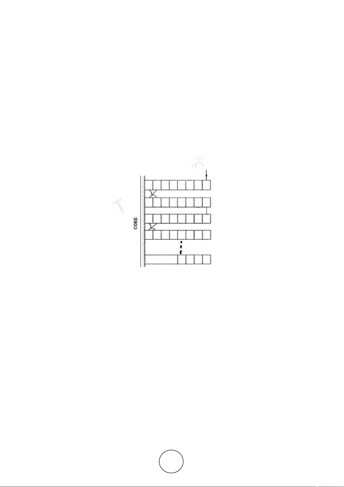
one disc to another, connecting at their ends to form a complete winding. Figure 1 shows the
configuration of interleaved configuration of transformer, which is used in transformer for
ensure the robust construction and greater mechanical strength. Discs are distanced from one
another with vertical strips attached with the pressboard.
Figure 1. Interleaved disc winding of transformer
IEC 60270 defines Partial Discharge as localized dielectric discharges in a partial area of a
solid or liquid electrical dielectric insulation system under high-voltage stress. PD activity is
influenced by the availability of conducting particle in transformer. This paper deals with
electrical analysis of transformer winding with the availability of particle at low, medium and
highest voltage disc. Electrical stress on the particle is measured by using finite element method
(FEM) and presented in this paper.
HV winding of this transformer comprises of two parts with one part containing 58 discs
which is identical with the other. As only high voltage side of the transformer is prone to PD,
analysis is done for the HV side only. The height of 58 discs is 975.3mm. The gap between
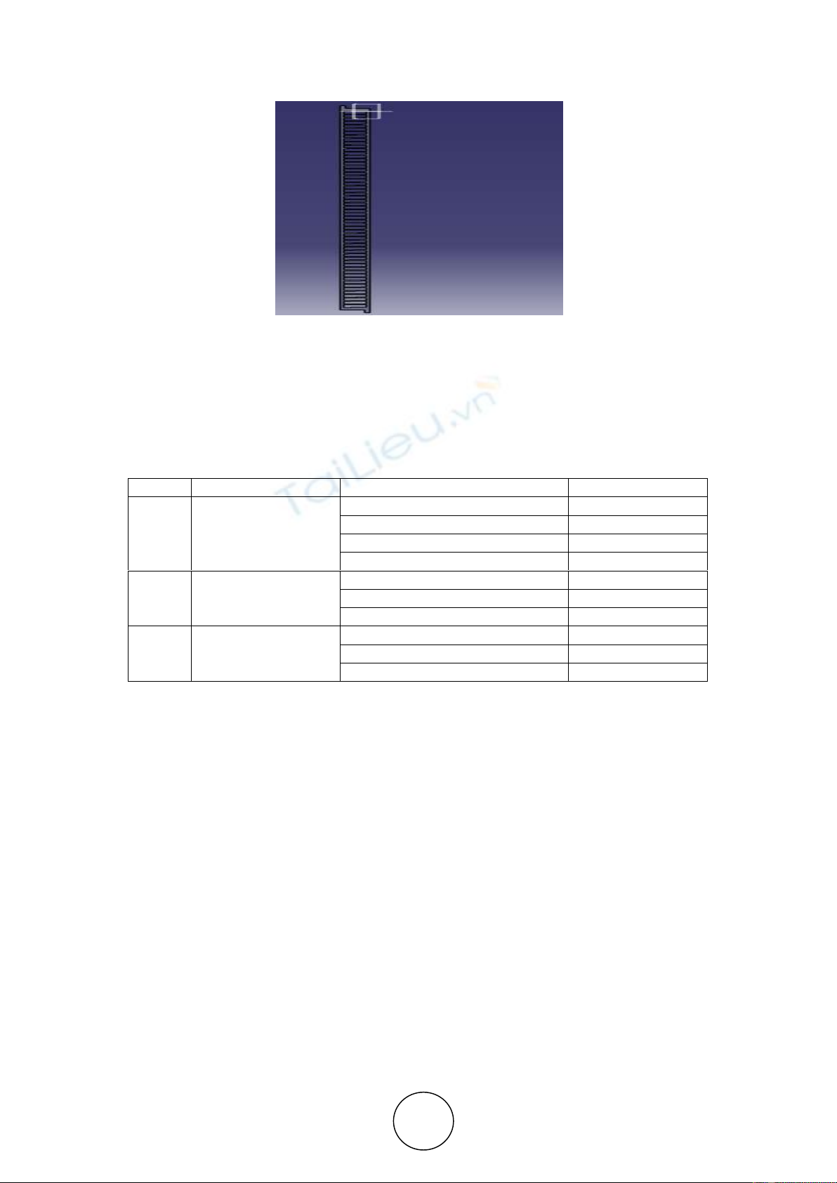
cylinder and disc is 8mm. The width of a given transformer is 61mm and height of each disc is
12.85 mm respectively. The outer and inner diameter of coil is 1408mm and 1286mm
respectively. The spacing between discs is 4mm.The geometrical designing is done in
Computer Aided Three-dimensional Interactive Application (Catia V5 R20). Figure 2 illustrates
the cross-section of HV winding of a power transformer.
Finite Element Analysis of Power Transformer
http://www.iaeme.com/IJMET/index.asp 1386 editor@iaeme.com
Figure 2. HV winding of a transformer
Each disc of HV winding is energized with voltages. Highest voltage in this transformer is
127.12KV and the disc with least voltage is 77.09KV. Discs are numbered from top to
bottom.The physical properties of solid and liquid insulation transformer material are taken into
consideration for simulation. The typical values are shown in Table 1.
Table 1 Material Properties
S.No.
Material
Properties
Values
1.
Oil
Density (Kg/m3)
890
Specific heat (J/kg-k)
2000
Thermal Conductivity (W/m-k)
0.109
Viscosity (kg/m-s)
0.02403
2.
Paper
Density
900
Specific heat
1500
Thermal Conductivity
0.5
3.
Pressboard
Density
1066
Specific heat
1260
Thermal Conductivity
0.151
A spherical particle of copper material is made available near the highest, low and medium
voltage disc. For the simulation, following discs with voltages are considered for the electrical
impact.
High voltage at Disc 1: 127.12 KV
Medium voltage at Disc 52: 82.34 KV
Low voltage at Disc 58: 77.09 KV
3. RESULT
Electrical analysis helps in peruse about electrical voltage, current, electrical field intensity and
current density of a model.The particle is made available at the places as discussed above. It
also includes analysis by altering the size of metallic particle by changing the diameter. Three
points of impacts are considered in this investigation at one of the higher, medium and lower
voltage discs. Points of impacts are derived from REF [1].
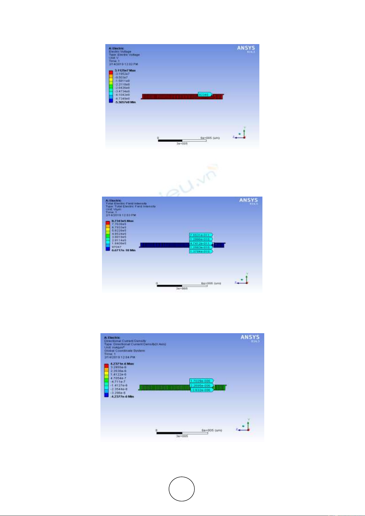
3.1. Electrical analysis of at disc no. 52
The copper spherical particle of diameter 1mm is considered to be present on the disc 52 with
medium voltage of 82.34 kV. Cross-section of energized HV winding is shown in figure 3.
Dr. N. Vasantha Gowri and Zainab Akthar
http://www.iaeme.com/IJMET/index.asp 1387 editor@iaeme.com
Figure 3 Cross section of energized HV winding
Electric field intensity on the particle when particle strikes on disc 52 is given in Figure 4.
The Electric field intensity elucidates the strength of electric field at a point, due to the presence
of electric voltage. On particle, it is 1.2986e-9 KV/cm.
Figure 4. Electric Field Intensity on the particle
Figure 5 represents Directional current density which allows viewing individual vector
component as contours. Its value is 2.2695e-006 mA/µm2 in x-direction.
Figure 5 Directional Current Density
Finite Element Analysis of Power Transformer
http://www.iaeme.com/IJMET/index.asp 1388 editor@iaeme.com
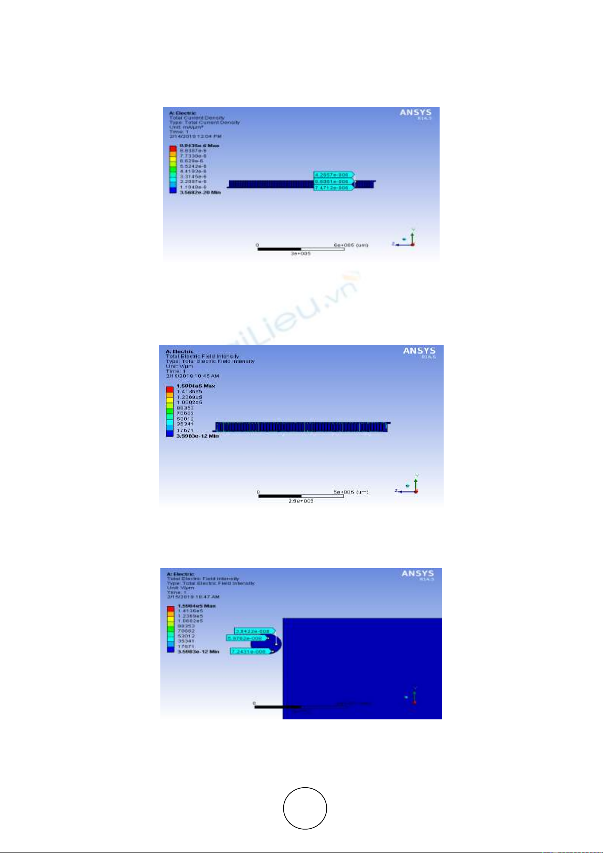
Figure 6 shows the simulation result for total current density due to the presence of electric
voltage, the amount of current flowing through per unit area which is 8.6061 mA/µm2.
Figure 6. Total Current Density
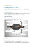
3.2. Electric analysis of dia. 2mm on disc 52
Here, analysis result is observed with increased diameter. Figure 7 shows the conducting
particle of diameter 2mm is present on disc no. 52.The electric field intensity is analysed.
Figure 7 Electric Field Intensity
Figure 8 shows the EFI due to the presence of electric voltage with increased diameter of
size 2mm is 5.9762e-7KV/cm on the particle.
Figure 8 Electric Field Intensity on conducting particle
Figure 9 shows the directional field at the palce of particle and measured as 3.5999e-003 mA/
µm2. It gives electric field intensity on the particle in x-direction.


![Sổ giáo án thực hành Máy DVD Trần Duy Khánh [chuẩn nhất]](https://cdn.tailieu.vn/images/document/thumbnail/2017/20170313/kakavt20/135x160/8341489413963.jpg)