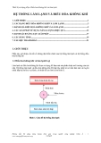
GLOBAL CHILLER
30GX 082-358
30HXC 080-375
Screw Compressor Water-
Cooled Liquid Chillers and
Air-Cooled Liquid Chillers
Nominal cooling capacity 30HXC 291-1308 kW
Nominal cooling capacity 30GX 284-1214 kW
50 Hz
Installation, operation and maintenance instructions

2
The cover photograph is for illustrative purposes only and is not part of any offer for sale or contract.
LIST OF CONTENTS
1 - INTRODUCTION ....................................................................................................................................................................... 4
1.1 - Installation safety considerations .............................................................................................................................................. 4
1.2 - Equipment and components under pressure .............................................................................................................................. 4
1.3 - Maintenance safety considerations ............................................................................................................................................4
1.4 - Repair safety considerations ...................................................................................................................................................... 5
2 - PRELIMINARY CHECKS ........................................................................................................................................................ 6
2.1 - Check equipment received ......................................................................................................................................................... 6
2.2 - Moving and siting the unit ......................................................................................................................................................... 6
3 - DIMENSIONS, CLEARANCES, WEIGHT DISTRIBUTION .............................................................................................. 7
3.1 - 30HXC 080-190 ......................................................................................................................................................................... 7
3.2 - 30HXC 200-375 ......................................................................................................................................................................... 8
3.3 - 30GX 082-182 ............................................................................................................................................................................ 9
3.4 - 30GX 207-358 .......................................................................................................................................................................... 10
3.5 - Multiple chiller installation .....................................................................................................................................................11
4 - LIFTING INSTRUCTIONS .....................................................................................................................................................12
4.1 - 30HXC 080-190 .......................................................................................................................................................................12
4.2 - 30HXC 200-285 .......................................................................................................................................................................12
4.3 - 30HXC 310-375 .......................................................................................................................................................................12
4.4 - 30GX 082-162 .......................................................................................................................................................................... 13
4.5 - 30GX 182 ................................................................................................................................................................................. 13
4.6 - 30GX 207-267 .......................................................................................................................................................................... 14
4.7 - 30GX 298-358 .......................................................................................................................................................................... 14
5 - PHYSICAL AND ELECTRICAL DATA FOR 30HXC UNITS ...........................................................................................15
5.1 - Physical data 30HXC ...............................................................................................................................................................15
5.2 - Electrical data 30HXC ............................................................................................................................................................. 15
5.3 - Electrical data, 30HXC compressors ....................................................................................................................................... 16
5.4 - Electrical data for 30HXC units with high condensing temperatures (option 150/150A) ...................................................... 16
6 - PHYSICAL AND ELECTRICAL DATA FOR UNITS 30GX.............................................................................................. 18
6.1 - Physical data 30GX..................................................................................................................................................................18
6.2 - Electrical data 30GX ................................................................................................................................................................ 18
6.3 - Electrical data, 30GX and 30HXC compressors, option 150 + 150A .....................................................................................19
7 - APPLICATION DATA .............................................................................................................................................................20
7.1 - Unit operating range ................................................................................................................................................................ 20
7.2 - Minimum chilled water flow ................................................................................................................................................... 20
7.3 - Maximum chilled water flow ................................................................................................................................................... 21
7.4 - Variable flow evaporator ......................................................................................................................................................... 21
7.5 - System minimum water volume .............................................................................................................................................. 21
7.6 - Cooler flow rate (l/s) ................................................................................................................................................................ 21
7.7 - Condenser flow rate (l/s) .......................................................................................................................................................... 21
7.8 - Evaporator pressure drop curve ...............................................................................................................................................22
7.9 - Condenser pressure drop curve ................................................................................................................................................22
8 - ELECTRICAL CONNECTION .............................................................................................................................................. 23
8.1 - Electrical connections 30HXC units ....................................................................................................................................... 23
8.1 - Electrical connections 30HXC units (cont’d) .........................................................................................................................24
8.2 - Electrical connections 30GX units ..........................................................................................................................................25
8.3 - Power supply ............................................................................................................................................................................ 27
8.4 - Voltage phase imbalance (%) ..................................................................................................................................................27
8.5 - Recommended wire sections ................................................................................................................................................... 29

3
9 - WATER CONNECTIONS ....................................................................................................................................................... 31
9.1 - Operating precautions ..............................................................................................................................................................31
9.2 - Water connections .................................................................................................................................................................... 31
9.3 - Flow control ............................................................................................................................................................................. 31
9.4 - Evaporator (and condenser for the 30HXC) water box bolt tightening .................................................................................. 32
9.5 - Frost protection ........................................................................................................................................................................ 32
9.6 - Operation of two units in master/slave mode .......................................................................................................................... 33
10 - MAJOR SYSTEM COMPONENTS AND OPERATION DATA ...................................................................................... 34
10.1 - Geared twin screw compressor .............................................................................................................................................. 34
10.2 - Evaporator ..............................................................................................................................................................................34
10.3 - Condenser and oil separator (30HXC) .................................................................................................................................. 34
10.4 - Oil separator (30GX) ............................................................................................................................................................. 34
10.5 - Electronic expansion device (EXD) ......................................................................................................................................34
10.6 - Economizer ............................................................................................................................................................................ 34
10.7 - Oil pumps ............................................................................................................................................................................... 35
10.8 - Motor cooling valves ............................................................................................................................................................. 35
10.9 - Sensors ................................................................................................................................................................................... 35
10.10 - 30GX fan arrangement ......................................................................................................................................................... 35
11 - MAIN OPTIONS AND ACCESSORIES .............................................................................................................................. 36
11.1 - Compressor suction valves (option 92) ................................................................................................................................. 36
11.2 - Compressor and evaporator noise insulation (30GX - option 14A) ......................................................................................36
11.3 - Low-noise 30GX units equipped with acoustic panels (option 15) ......................................................................................36
11.4 - Evaporator frost protection (30GX - option 41A) ................................................................................................................. 36
11.5 - Year-round operation of 30GX units (option 28) .................................................................................................................. 36
11.6 - Soft Start for 3- and 4-compressor 30HXC and 30GX units (option 25) .............................................................................. 36
11.7 - Electric protection level of the 30HXC control boxes to IP44C (option 20) ....................................................................... 37
11.8 - Tropicalised control box for 30HXC and 30GX units (option 22) ....................................................................................... 37
11.9 - Brine units for low-temperature evaporator leaving applications (option 5) ....................................................................... 37
11.10 - Disassembled 30HXC units (option 52) .............................................................................................................................. 37
11.11 - Available fan pressure of 150 Pa for 30GX units (option 12) ............................................................................................. 37
12 - MAINTENANCE ....................................................................................................................................................................38
12.1 - Refrigerant charging - adding charge .................................................................................................................................... 38
12.2 - Indication of low charge on a 30HXC system ....................................................................................................................... 38
12.3 - Pressure transducers ............................................................................................................................................................... 39
12.4 - Oil charging - low oil recharging .......................................................................................................................................... 39
12.5 - Integral oil filter change ........................................................................................................................................................39
12.6 - Filter change-out schedule ..................................................................................................................................................... 39
12.7 - Filter change-out procedure ................................................................................................................................................... 39
12.8 - Compressor replacement ........................................................................................................................................................ 40
13 - START-UP CKECKLIST FOR 30HXC/GX LIQUID CHILLERS (USE FOR JOB FILE) ........................................... 41

4
1 - INTRODUCTION
Prior to the initial start-up of the 30HXC/GX units, the people
involved in the on-site installation, start-up, operation, and
maintenance of this unit should be thoroughly familiar with these
instructions and the specific project data for the installation site.
The 30HXC/GX liquid chillers are designed to provide a very
high level of safety during installation, start-up, operation and
maintenance. They will provide safe and reliable service when
operated within their application range.
This manual provides the necessary information to familiarize
yourself with the control system before performing start-up
procedures. The procedures in this manual are arranged in the
sequence required for machine installation, start-up, operation
and maintenance.
Be sure you understand and follow the procedures and safety
precautions contained in the instructions supplied with the
machine, as well as those listed in this guide.
1.1 - Installation safety considerations
After the unit has been received, when it is ready to be installed
or reinstalled, and before it is started up, it must be inspected
for damage. Check that the refrigerant circuit(s) is (are) intact,
especially that no components or pipes have shifted (e.g. follow-
ing a shock). If in doubt, carry out a leak tightness check and
verify with the manufacturer that the circuit integrity has not
been impaired. If damage is detected upon receipt, immediately
file a claim with the shipping company.
Do not remove the skid or the packaging until the unit is in its
final position. These units can be moved with a fork lift truck,
as long as the forks are positioned in the right place and
direction on the unit.
The units can also be lifted with slings, using only the desig-
nated lifting points marked on the unit.
These units are not designed to be lifted from above. Use
slings with the correct capacity, and always follow the lifting
instructions on the certified drawings supplied with the unit.
Safety is only guaranteed, if these instructions are carefully
followed. If this is not the case, there is a risk of material
deterioration and injuries to personnel.
Never cover any safety devices.
This applies to the valve in the hydronic circuit and the valve(s)
in the refrigerant circuit(s) .
Ensure that the valves are correctly installed, before opera-
ting the unit.
Provide a drain in the discharge circuit, close to each valve,
to avoid an accumulation of condensate or rain water.
Ensure that no refrigerant can escape at the safety valves into
the building interior. The outlet from relief valves must be
vented outdoors. Ensure good ventilation, as accumulation of
refrigerant in an enclosed space can displace oxygen and
cause asphyxiation or explosions.
Inhalation of high concentrations of vapour is harmful and
may cause heart irregularities, unconsciousness, or death.
Vapour is heavier than air and reduces the amount of oxygen
available for breathing. These products cause eye and skin
irritation. Decomposition products are hazardous.
1.2 - Equipment and components under pressure
These products incorporate equipment or components under
pressure, manufactured by Carrier or other manufacturers. We
recommend that you consult your appropriate national trade
association or the owner of the equipment or components under
pressure (declaration, re-qualification, retesting, etc.). The
characteristics of this equipment/these components are given
on the nameplate or in the required documentation, supplied
with the products.
1.3 - Maintenance safety considerations
Engineers working on the electric or refrigeration components
must be authorized and fully qualified to do so (electricians
trained and qualified in accordance with IEC 60364 Classifica-
tion BA4).
All refrigerant circuit repairs must be carried out by a trained
person, fully qualified to work on these units. He must have
been trained and be familiar with the equipment and the
installation. All welding operations must be carried out by
qualified specialists.
Never work on a unit that is still energized.
Never work on any of the electrical components, until the
general power supply to the unit has been cut using the
disconnect switch(es) in the control box(es).
If any maintenance operations are carried out on the unit,
lock the power supply circuit in the open position ahead of
the machine.
If the work is interrupted, always ensure that all circuits are
still deenergized before resuming the work.
ATTENTION: Even if the compressor motors have been
switched off, the power circuit remains energized, unless the
unit or circuit disconnect switch is open. Refer to the wiring
diagram for further details. Attach appropriate safety labels.
Once a year check that the high-pressure safety switch is
correctly connected and that it cuts out at the correct value.
At least once a year thoroughly inspect the protection devices
(valves). If the machine operates in a corrosive environment,
inspect the protection devices more frequently.
Regularly carry out leak tests and immediately repair any leaks.

5
Do not re-use disposable (non-returnable) cylinders or attempt
to refill them. It is dangerous and illegal. When cylinders are
empty, evacuate the remaining gas pressure, and move the
cylinders to a place designated for their recovery. Do not
incinerate.
Do not attempt to remove refrigerant circuit components or
fittings, while the machine is under pressure or while it is
running. Be sure pressure is at 0 kPa before removing
components or opening a circuit.
Do not attempt to repair or recondition any safety devices
when corrosion or build-up of foreign material (rust, dirt,
scale, etc.) is found within the valve body or mechanism. If
necessary, replace the device. Do not install safety valves in
series or backwards.
CAUTION:
Do not step on refrigerant lines. The lines can break under
the weight and release refrigerant, causing personal injury.
Do not climb on a machine. Use a platform, or staging to
work at higher levels.
Use mechanical lifting equipment (crane, hoist, winch, etc.)
to lift or move heavy components. For lighter components,
use lifting equipment when there is a risk of slipping or losing
your balance.
Use only original replacement parts for any repair or compo-
nent replacement. Consult the list of replacement parts that
corresponds to the specification of the original equipment.
Do not drain water circuits containing industrial brines,
without informing the technical service department at the
installation site or a competent body first.
Close the entering and leaving water shutoff valves and
purge the unit hydronic circuit, before working on the
components installed on the circuit (screen filter, pump, water
flow switch, etc.).
Do not loosen the water box bolts until the water boxes have
been completely drained.
Periodically inspect all valves, fittings and pipes of the
refrigerant and hydronic circuits to ensure that they do not
show any corrosion or any signs of leaks.
1.4 - Repair safety considerations
All installation parts must be maintained by the personnel in
charge, in order to avoid material deterioration and injuries to
people. Faults and leaks must be repaired immediately. The
authorized technician must have the responsibility to repair the
fault immediately. Each time repairs have been carried out to
the unit, the operation of the safety devices must be re-checked.
If a leak occurs, evacuate all refrigerant, repair the leak
detected and recharge the circuit with the total R134a charge,
as indicated on the unit name plate. Certain parts of the circuit
can be isolated. If leaks occur in these sections it is possible to
top up the refrigerant charge. Refer to chapter 12.1 ‘Refrigerant
charging - adding charge’. Only charge liquid refrigerant
R134a at the liquid line.
Ensure that you are using the correct refrigerant type before
recharging the unit.
Charging any refrigerant other than the original charge type
(R134a) will impair machine operation and can even lead to
a destruction of the compressors. The compressors operating
with this refrigerant type are lubricated with a synthetic polyol-
ester oil.
Do not use oxygen to purge lines or to pressurize a machine
for any purpose. Oxygen gas reacts violently with oil, grease,
and other common substances.
Never exceed the specified maximum operating pressures.
Verify the allowable maximum high- and low-side test
pressures by checking the instructions in this manual and the
pressures given on the unit name plate.
Do not use air for leak testing. Use only refrigerant or dry
nitrogen.
Do not unweld or flamecut the refrigerant lines or any refri-
gerant circuit component until all refrigerant (liquid and
vapour) has been removed from chiller. Traces of vapour
should be displaced with dry air nitrogen. Refrigerant in
contact with an open flame produces toxic gases.
The necessary protection equipment must be available, and
appropriate fire extinguishers for the system and the refrigerant
type used must be within easy reach.
Do not siphon refrigerant.
Avoid spilling liquid refrigerant on skin or splashing it into
the eyes. Use safety goggles. Wash any spills from the skin
with soap and water. If liquid refrigerant enters the eyes,
immediately and abundantly flush the eyes with water and
consult a doctor.
Never apply an open flame or live steam to a refrigerant
container. Dangerous overpressure can result. If it is
necessary to heat refrigerant, use only warm water.
![Nội dung môn học Turbine - Nhà máy Nhiệt điện [Chuẩn SEO]](https://cdn.tailieu.vn/images/document/thumbnail/2025/20250922/thieuquan520@gmail.com/135x160/16251758512302.jpg)
![Tiêu chuẩn kỹ năng nghề vận hành, sửa chữa thiết bị lạnh: [Chuẩn nhất/Mới nhất]](https://cdn.tailieu.vn/images/document/thumbnail/2016/20160611/tangtuy15/135x160/5891465607868.jpg)


![Hệ thống làm lạnh (phần 2): [Hướng dẫn/Tìm hiểu/Kinh nghiệm]](https://cdn.tailieu.vn/images/document/thumbnail/2011/20111124/gauhaman123/135x160/he_thong_lah_11__0808.jpg)
![Giải pháp chống nóng [Năm]: Tư vấn, Kinh nghiệm, Cách thực hiện](https://cdn.tailieu.vn/images/document/thumbnail/2011/20110804/nha_xinh/135x160/noi_that_3_62__2191.jpg)


![Giáo trình Tính toán thiết kế hệ thống máy lạnh và điều hoà không khí (CĐ) - Trường Cao đẳng Công nghiệp Thanh Hóa [Mới nhất]](https://cdn.tailieu.vn/images/document/thumbnail/2026/20260511/hoabattu2026/135x160/70831778842526.jpg)


%20--%3e%3cdefs%3e%3cstyle%3e%20.st0%20{%20fill:%20%23fff;%20}%20.st1%20{%20fill:%20%237800fa;%20}%20%3c/style%3e%3c/defs%3e%3cpath%20class='st1'%20d='M117.78,12.18H43.11c2.9,3.47,4.65,7.94,4.65,12.82,0,5.6-2.3,10.66-6.01,14.29h76.02l7.22-13.56-7.22-13.56Z'/%3e%3cg%3e%3cpath%20class='st0'%20d='M53.58,26.17h-.59v-1.46h.59v-4.96h2.83c1.78,0,2.67.94,2.67,2.82v5.76c0,1.87-.89,2.81-2.67,2.81h-2.83v-4.96ZM55.36,21.37v3.34h1.1v1.46h-1.1v3.34h1.01c.61,0,.91-.37.91-1.1v-5.93c0-.74-.3-1.1-.91-1.1h-1.01Z'/%3e%3cpath%20class='st0'%20d='M65.99,31.14h-1.8l-.31-2.07h-2.19l-.31,2.07h-1.64l1.82-11.39h2.62l1.82,11.39ZM65.28,18.04c-.25.46-.51.77-.75.94-.21.15-.47.22-.79.22-.26,0-.57-.07-.92-.22l-.38-.15c-.14-.05-.26-.07-.37-.07-.3,0-.53.18-.71.54l-.91-.68c.25-.46.51-.77.75-.94.21-.14.48-.21.79-.21.26,0,.57.07.92.21l.38.15c.14.05.26.07.37.07.3,0,.53-.18.71-.54l.91.68ZM61.91,27.52h1.73l-.87-5.76-.87,5.76Z'/%3e%3cpath%20class='st0'%20d='M74.53,26.89v1.52c0,1.91-.89,2.86-2.67,2.86s-2.67-.95-2.67-2.86v-5.93c0-1.91.89-2.86,2.67-2.86s2.67.95,2.67,2.86v1.11h-1.69v-1.22c0-.75-.31-1.12-.93-1.12s-.93.37-.93,1.12v6.15c0,.74.31,1.11.93,1.11s.93-.37.93-1.11v-1.63h1.69Z'/%3e%3cpath%20class='st0'%20d='M81.4,31.14h-1.8l-.31-2.07h-2.19l-.31,2.07h-1.64l1.82-11.39h2.62l1.82,11.39ZM75.9,19.2l1.52-1.91h1.71l1.51,1.91h-1.61l-.76-.95-.75.95h-1.61ZM77.32,27.52h1.73l-.87-5.76-.87,5.76ZM83.1,15.99l-1.76,1.91h-1.26l1.17-1.91h1.86Z'/%3e%3cpath%20class='st0'%20d='M84.86,19.75c1.78,0,2.67.94,2.67,2.82v1.48c0,1.87-.89,2.81-2.67,2.81h-.85v4.28h-1.79v-11.39h2.64ZM84.01,21.37v3.86h.85c.58,0,.87-.36.87-1.08v-1.71c0-.71-.29-1.07-.87-1.07h-.85Z'/%3e%3cpath%20class='st0'%20d='M93.51,19.75c1.78,0,2.67.94,2.67,2.82v1.48c0,1.87-.89,2.81-2.67,2.81h-.85v4.28h-1.79v-11.39h2.64ZM92.66,21.37v3.86h.85c.58,0,.87-.36.87-1.08v-1.71c0-.71-.29-1.07-.87-1.07h-.85Z'/%3e%3cpath%20class='st0'%20d='M98.8,31.14h-1.79v-11.39h1.79v4.88h2.03v-4.88h1.83v11.39h-1.83v-4.88h-2.03v4.88Z'/%3e%3cpath%20class='st0'%20d='M105.36,24.55h2.46v1.62h-2.46v3.34h3.09v1.63h-4.88v-11.39h4.88v1.63h-3.09v3.18ZM108.17,17.29l-1.76,1.91h-1.26l1.17-1.91h1.86Z'/%3e%3cpath%20class='st0'%20d='M112.2,19.75c1.78,0,2.67.94,2.67,2.82v1.48c0,1.87-.89,2.81-2.67,2.81h-.85v4.28h-1.79v-11.39h2.64ZM111.35,21.37v3.86h.85c.58,0,.87-.36.87-1.08v-1.71c0-.71-.29-1.07-.87-1.07h-.85Z'/%3e%3c/g%3e%3ccircle%20class='st1'%20cx='25'%20cy='25'%20r='20'/%3e%3cpath%20class='st0'%20d='M32.78,19.27c2.92,0,4.43,2.55,5.28,5.33l.71,2.17c.14.38-.33.75-.71.75h-5.61c.19-.33.24-.71.09-1.08l-.75-2.45c-.43-1.32-.99-2.64-1.79-3.77.75-.57,1.65-.94,2.78-.94h0ZM25,18.38c3.25,0,4.9,2.78,5.89,5.89l.76,2.45c.14.42-.33.8-.8.8h-11.69c-.42,0-.94-.38-.8-.8l.75-2.45c.99-3.11,2.64-5.89,5.89-5.89h0ZM25,11.35c1.74,0,3.11,1.37,3.11,3.11s-1.37,3.11-3.11,3.11-3.11-1.41-3.11-3.11,1.41-3.11,3.11-3.11h0ZM17.27,19.27c1.08,0,1.98.38,2.73.94-.8,1.13-1.37,2.45-1.74,3.77l-.8,2.45c-.14.38-.05.75.09,1.08h-5.56c-.42,0-.9-.38-.75-.75l.71-2.17c.9-2.78,2.41-5.33,5.33-5.33h0ZM17.27,12.91c1.51,0,2.78,1.27,2.78,2.83s-1.27,2.83-2.78,2.83-2.83-1.27-2.83-2.83,1.27-2.83,2.83-2.83h0ZM32.78,12.91c1.56,0,2.78,1.27,2.78,2.83s-1.23,2.83-2.78,2.83-2.83-1.27-2.83-2.83,1.27-2.83,2.83-2.83h0ZM27.07,28.56v.09c0,.57-.24,1.08-.61,1.46h0v.05c-.38.33-.9.57-1.46.57s-1.08-.24-1.46-.61h0c-.38-.38-.61-.9-.61-1.46v-.09h1.41v.09c0,.19.05.38.19.47v.05c.09.09.28.19.47.19s.38-.09.47-.19v-.05c.14-.09.24-.28.24-.47t-.05-.09h1.41ZM30.99,28.56v.09c0,1.65-.66,3.16-1.74,4.24-1.08,1.08-2.59,1.79-4.24,1.79s-3.16-.71-4.24-1.79l-.05-.05c-1.04-1.08-1.7-2.55-1.7-4.2v-.09h1.41v.09c0,1.27.47,2.4,1.27,3.25h.05c.85.85,1.98,1.37,3.25,1.37s2.4-.52,3.25-1.37c.85-.8,1.37-1.98,1.37-3.25v-.09h1.37ZM34.99,28.56v.09c0,2.78-1.13,5.28-2.92,7.07-1.79,1.79-4.29,2.92-7.07,2.92s-5.23-1.13-7.07-2.92c-1.79-1.79-2.92-4.29-2.92-7.07v-.09h1.41v.09c0,2.4.94,4.53,2.5,6.08,1.56,1.56,3.72,2.5,6.08,2.5s4.52-.94,6.08-2.5c1.56-1.56,2.5-3.68,2.5-6.08v-.09h1.41Z'/%3e%3c/svg%3e)