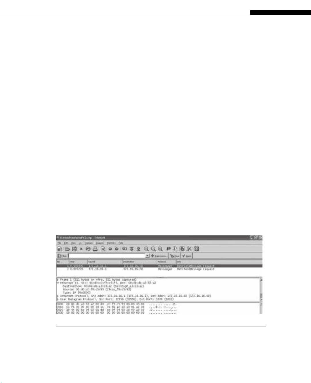
FIGURE 3.3
Ethernet frames on a wired LAN at the end of a DSL link. Capturing raw DSL frame “on the wire”
is not frequently done, and is diffi cult without very expensive and specialized equipment.
On the network end of the DSL link, the link terminates at a DSL access multiplexer
(DSLAM), typically using IP or ATM technology.
At the user end of the DSL link on the Illustrated Network, the offi ce in the home
uses both a wired and a wireless network. This is a common arrangement today: Peo-
ple with laptops can wander, but desktop PCs usually stay put. The wireless network
encapsulates packets and sends them to a special device in the home (a wireless access
point, often built into a DSL router).
What kind of frames does the DSL link use? That’s hard to determine, because the
DSL modem is upstream of the DSL router in most cases (sometimes on the side of the
house, sometimes closer to the service provider). The wired LAN between DSL router
and computer uses the same type of Ethernet frames we saw on LAN1 and LAN2. On a
wired LAN, Ethereal will always capture Ethernet II frames, as shown in Figure 3.3.
What can we learn about DSL itself? Well, we can access the DSL router using a Web
browser and see what kinds of information are available. Figure 3.4 shows the basic
setup screen of the Linksys DSL router (although it’s really not doing any real routing,
just functioning as a simple gateway between ISP and home LAN).
Because this is a working LAN, I’ve restored the default names and addresses for
this example. The router itself is WRT54G (a product designation), and the ISP does not
expect only one host to use the DSL link, so no host or domain name is required. We’ll
talk about the maximum transmission unit (MTU) size later in this chapter. This is set
automatically on the link.
The DSL router itself uses IPv4 address 192.168.1.1. We’ll talk about what the sub-
net mask does in Chapter 4. The router hands out IP addresses as needed to devices on
the home network, starting with 192.168.1.100, and it uses the Dynamic Host Confi gu-
ration Protocol (DHCP) to do this. We’ll talk about DHCP in Chapter 18.
CHAPTER 3 Network Link Technologies 79
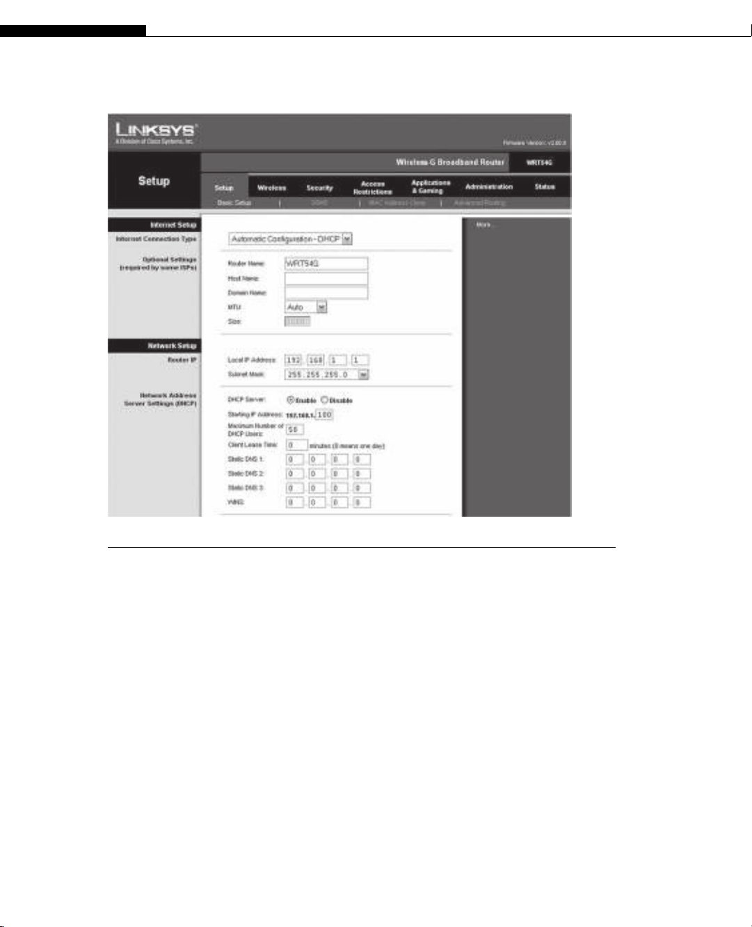
FIGURE 3.4
Basic setup screen for a DSL link. We’ll talk about all of these confi guration parameters and
protocols, such as subnet masks and DHCP, in later chapters.
What kinds of statistics are available on the DSL router? Not much on this model.
There are simple incoming and outgoing logs, but these capture only the most basic
information about addresses and ports. A small section of the outgoing log is shown in
Table 3.1.
These are all Web browser entries that were run with names, not IP addresses (Yahoo
is one of them). The table lists the addresses because the residential gateway does not
bother to look the names up. However, instead of presenting the port numbers, the log
interprets them as a service name (www is port 80 on most servers).
We’ll take a more detailed look at DSL later in this chapter. Now, let’s take a look at
the fourth and last link type used on the Illustrated Network: the four available wireless
links used to hook a laptop and printer up to the home offi ce DSL router.
The wireless implementation is a fairly straightforward bridging exercise. A single
wireless interface is bridged in software with the Ethernets in the box. The wireless
network is a single broadcast/collision domain.
80 PART I Networking Basics
Displaying Wireless Links
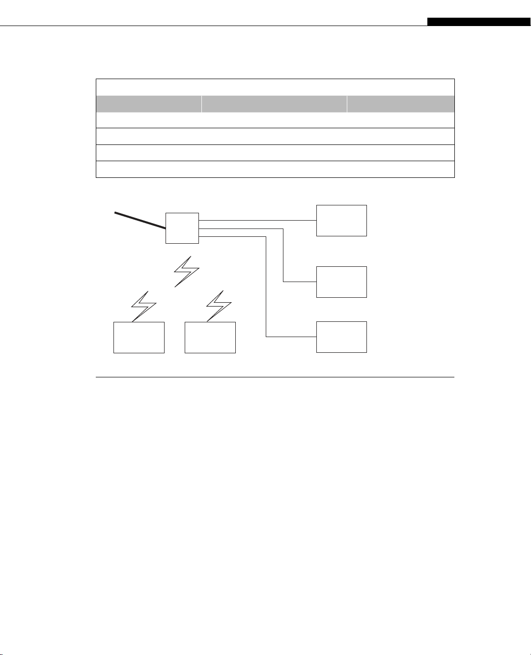
The physical arrangement of the home offi ce equipment used on the Illustrated Net-
work is shown in Figure 3.5. In addition to the three wired PCs (used for various
equipment confi gurations), there are two wireless links. One is used by the laptop for
mobility, and the other is used to share a color laser printer. The DSL router does not
have “ports” in the same sense as wired network devices, but it only supports up to four
wireless devices.
The wireless link from the laptop to the DSL router, which uses something called
IEEE 802.11g (sometimes called Wireless-G), is a distinct Layer 2 network technology
and should not use Ethernet II frames. Let’s make sure.
Capturing traffi c at the wireless frame level requires special software and special
drivers for the wireless network adapter card. The examples in this chapter use infor-
mation from a wireless packet sniffer called Airopeek NX from Wildpackets.
Table 3.1 Outgoing Log Table from DSL Router
LAN IP Destination URL/IP Service/Port Number
192.168.1.101 202.43.195.13 www
192.168.1.101 64.86.142.99 www
192.168.1.101 202.43.195.52 www
192.168.1.101 64.86.142.120 www
DSL Link to ISP
(4 Ethernet ports)
PC 1
PC 2
PC 3
DSL
Router
(4 wireless ports)
Laptop Color Laser
Printer
FIGURE 3.5
The home offi ce network for the Illustrated Network. Devices must have either Ethernet ports or
wireless interfaces (some have both). Not all printers are network-capable or wireless.
CHAPTER 3 Network Link Technologies 81
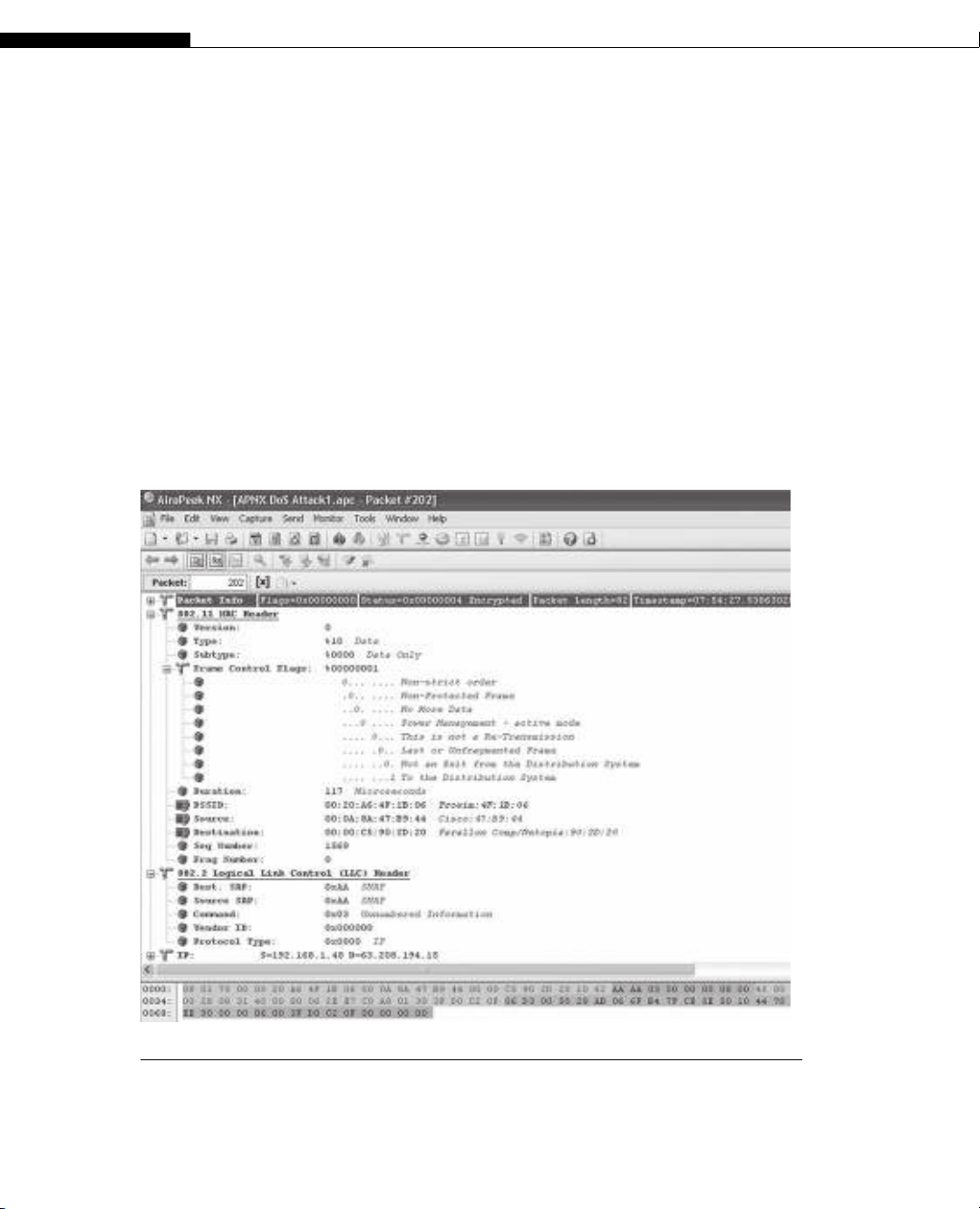
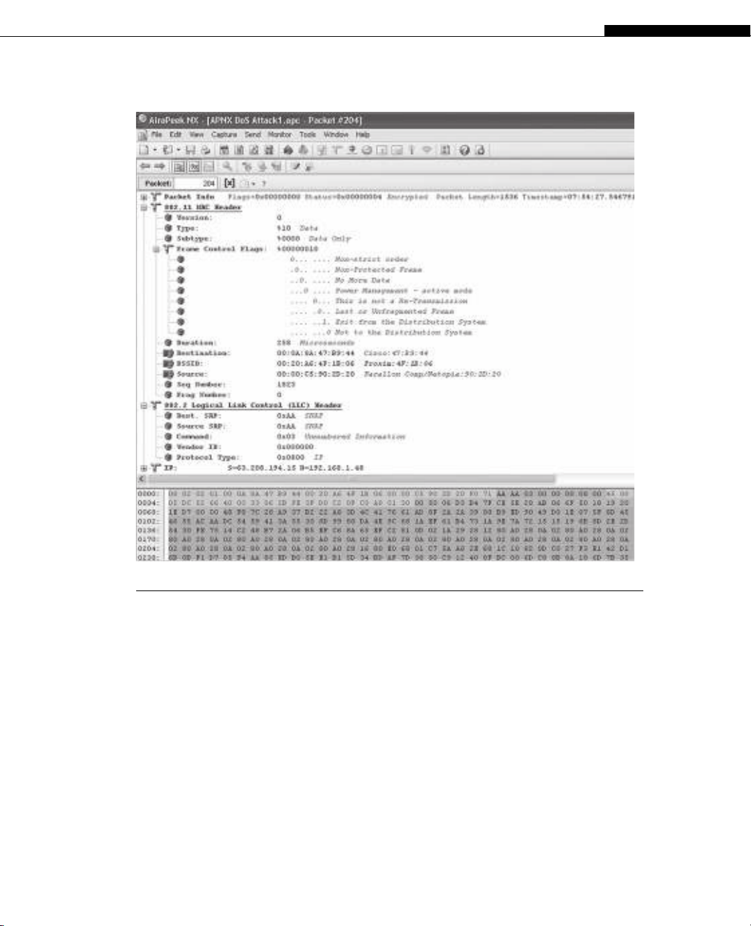
A sample capture of a data packet and frame from a wireless link is shown in
Figure 3.6.
Wireless LANs based on IEEE 802.11 use a distinct frame structure and a complex
data link layer protocol. We’ll talk about 802.11 shortly, but for now we should just note
that the Illustrated Network uses USB-attached wireless NICs, and few wireless sniffers
support these types of adapters.
The frame addressing and encapsulation on wireless LANs is much more compli-
cated than Ethernet. Note that the 802.11 MAC frame has three distinct MAC addresses,
labeled Destination, BSSID, and Source. The wireless LAN has to keep track of source,
destination, and wireless access point (Base Station System ID, or BSSID) addresses. Also
note that these are not really Ethernet II frames. The frames on the wireless link are
structured according to the IEEE 802.2 LLC header. These have “SNAP SAP, ” indicated
by 0xAA, in the frame, in contrast to Ethernet II frames, which are indicated by 0x01.
FIGURE 3.6
Data frame and packet on a wireless link. Note that the IEEE 802.11 MAC header is different
from the Ethernet in many ways and uses the IEEE 802.2 LLC inside.
82 PART I Networking Basics
The address fi elds in 802.11 also “shift” their meaning, as shown in Figure 3.7. The
fi elds are now BSSID, Source, and Destination. This is another capture from Airopeek
NX, showing the next data frame sent in the captured exchange. The address fi elds
have different meanings based on whether they are sent to the wireless router or are
received from the wireless router.
Frames and the Link Layer
In summary, we have seen that the connections on the Illustrated Network consist of
several types of links. There are wired Ethernet LANs and Gigabit Ethernet links, SONET
links and DSL links, and even a wired LAN in the home network. We’ve looked at some
of the frame types that carry information back and forth on the network connections.
FIGURE 3.7
The next data frame in the sequence, showing how the contents of the address fi elds shift based
on direction and type of wireless frame.
CHAPTER 3 Network Link Technologies 83


![Đề thi học kì 2 môn Nhập môn Mạng máy tính [kèm đáp án]](https://cdn.tailieu.vn/images/document/thumbnail/2025/20251014/lakim0906/135x160/23811760416180.jpg)


![Câu hỏi trắc nghiệm Mạng máy tính: Tổng hợp [mới nhất]](https://cdn.tailieu.vn/images/document/thumbnail/2025/20251001/kimphuong1001/135x160/15231759305303.jpg)
![Câu hỏi ôn tập An toàn mạng môn học: Tổng hợp [mới nhất]](https://cdn.tailieu.vn/images/document/thumbnail/2025/20250919/kimphuong1001/135x160/30511758269273.jpg)