REGULAR ARTICLE
Reector features and physics consideration issued from the Jules
Horowitz Reactor design analyses
Edwin Privas
*
and Laurent Chabert
Safety and Power Plant Process, Neutronic Shielding Criticality Department, TechnicAtome, Aix-en-Provence, France
Received: 16 June 2017 / Received in nal form: 28 November 2017 / Accepted: 31 May 2018
Abstract. Mechanic solicitations induced by neutron and photon interactions have to be featured for
components lifespan determination. TechnicAtome is in charge of both the design and building on behalf of CEA
of the 100 MW Jules Horowitz Reactor (JHR). This modular Material Testing Reactor is under construction in
southern France, with radioisotope production and material testing capabilities. Inner core components have
been designed based on mechanical and thermohydraulic considerations. Both studies require neutronic physical
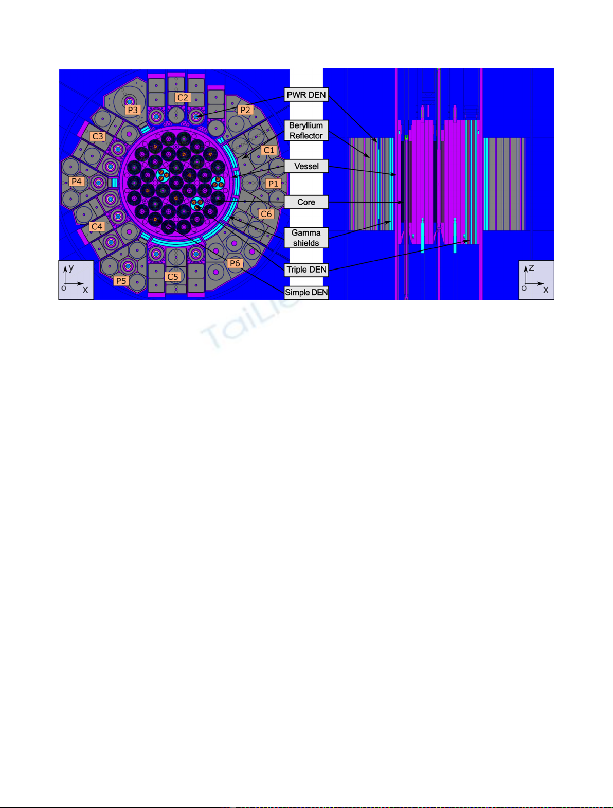
quantities like the neutron ux and deposited energies. The JHR reector is outside the primary loop and is
composed of beryllium. Gamma shields are partially positioned between the reector and the core to reduce
photon heating on aluminum structures. The design is completed and this paper deals with the neutronic and
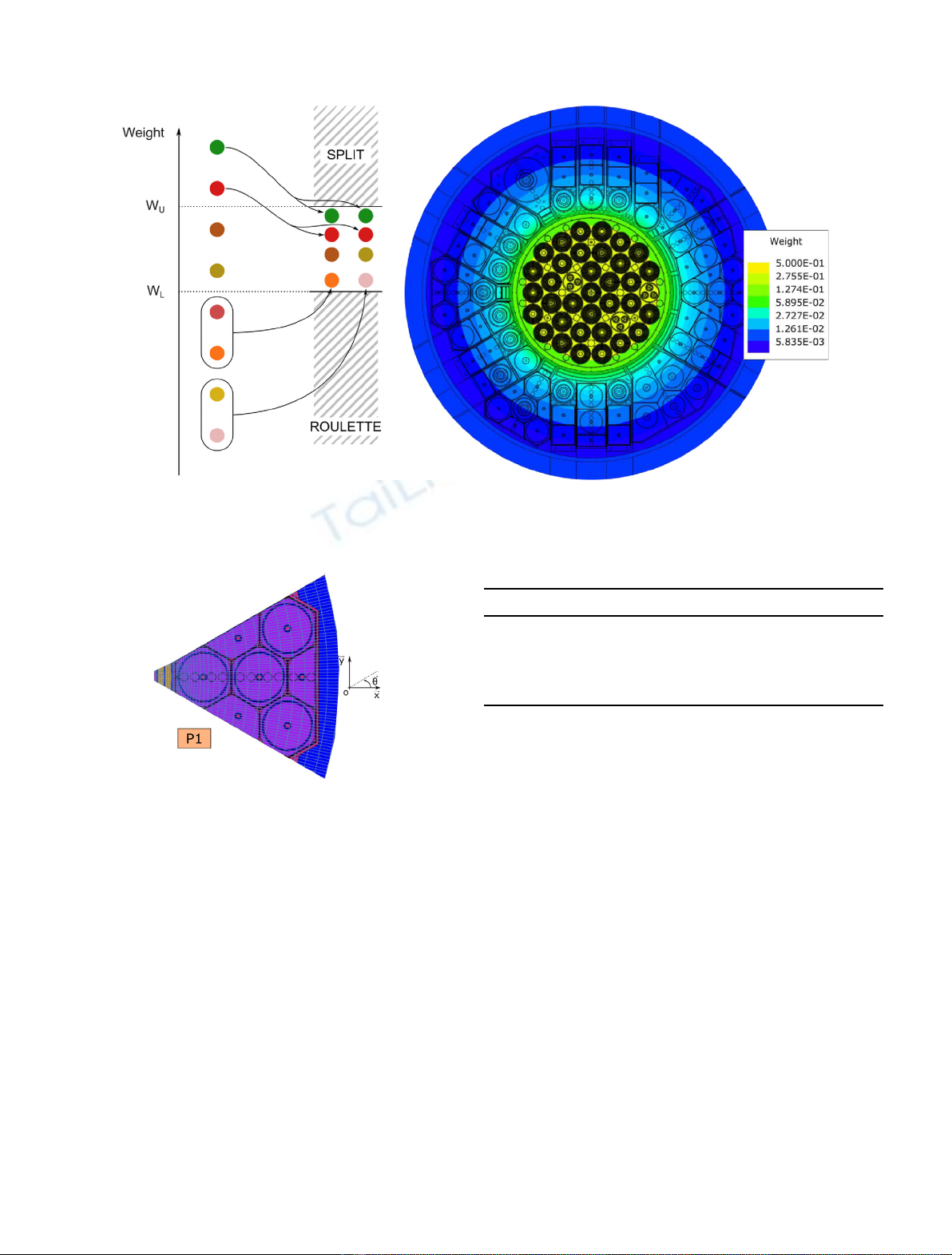
photonic impacts on the reector. A Monte Carlo methodology based on the MCNP code was developed to model
the reactor and enhance uxes and energy deposited maps. MCNPs mesh options are used over the detailed
geometry model. The convolution with mechanical meshes enables to determine neutronic parameters on local
structures, material by material. Time required for such modeling is very long if one requires results on every
mesh with a maximum uncertainty of 2% (1s). To reduce time calculation by a factor 3.5 on rened meshes,
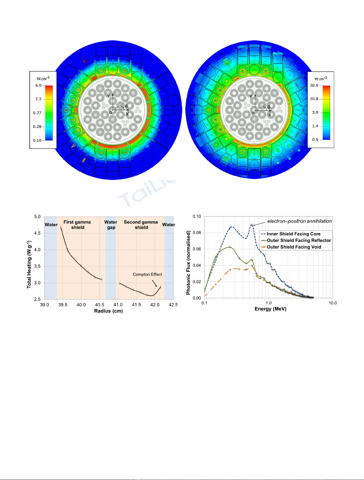
MCNP biasing methods have been used. Spatial distribution of the gamma heating shows the importance of the
interface with the surrounding area. For example, photon and neutron interactions close to the gamma shield
create numerous photons with lower energy adding heating at the shield interfaces. In order to keep high ux in
the experimental part of the reector, gamma shields are not continuously set around the reactor vessel.
Consequently, some photon leakage arises in the reector area, with limited impact on aluminum structures. The
overall thermal ux map shows local effects and gradients that have to be taken into account by the physics
studies. Material swellings are deduced from the uxes on all reector structures.
1 Introduction
Design and development of new research reactor like
Material Testing Reactors is mainly driven by the
materials qualication, the fuel behavior characterization
during nominal conditions or accident scenarios and the
radioisotope production. In this scope, the Jules Horowitz
Reactor (JHR) is intended to be a multipurpose research
reactor with the largest experimental capacity in Europe
[1]. One application will be to validate components both for
the current nuclear reactors of second and third gener-
ations and for the next generation, thanks to high neutron
ux (both in thermal and fast range and each around
510
14
n·cm
2
·s
1
). Experimental devices like ADELINE,
MADISON or MOLFY for
99
Mo production are designed
by CEA [2] and can be placed in serval part of the reactor.
JHR is designed by TechnicAtome to fulll the ux and
maximum heating requirement of such experimental
devices. HORUS V2.1 [3] chained with MCNP [4] are
used to compute neutronic physical quantities for thermo-
hydraulic and mechanical analysis [5].
This paper focuses on the main reector features and
neutronic methodology. Fine ux and heating distribution
over the reector will be discussed, leading to key design
parameters. A special care will be given to the gamma
shield and physics happening around. Finally, a mechani-
cal application using heating and ux will be presented,
showing the swelling of a sector.
2 Jules Horowitz Reactor
JHR is a 100 MW pool-type Material Testing Reactor
cooled by light water. The core rack is a 60 cm height
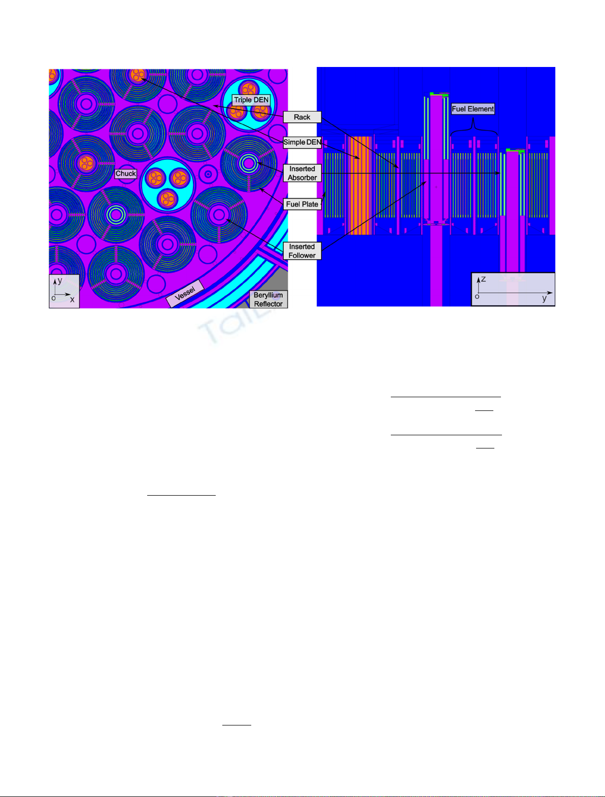
cylinder made of aluminum in which 37 drilled holes can
host 34 fuel elements and three large devices. Every fuel
assembly is composed of 8 cylindrical and concentric plates
hold together with three stiffeners. A U
3
-Si
2
metallic fuel is
*e-mail: edwin.privas@technicatome.com
EPJ Nuclear Sci. Technol. 4, 18 (2018)
©E. Privas and L. Chabert, published by EDP Sciences, 2018
https://doi.org/10.1051/epjn/2018040
Nuclear
Sciences
& Technologies
Available online at:
https://www.epj-n.org
This is an Open Access article distributed under the terms of the Creative Commons Attribution License (http://creativecommons.org/licenses/by/4.0),
which permits unrestricted use, distribution, and reproduction in any medium, provided the original work is properly cited.
considered for this study. A 3 cm height Al-B poisoned
insert positioned 1 cm above the top of each plate aims at
limiting the ux upwelling and heat deposition above the
ssile zone. This is mandatory because the water is warmer
and less pressurized in this zone inducing lower vaporiza-
tion margin.
Seven small test locations, called simple DEN, are
placed in the center of the cylindrical fuel plates in order to
have high fast ux. The other fuel elements are lled with
hafnium rods to handle reactor reactivity both to provide
depletion compensation and to ensure safety shutdowns.
They are geometrically composed of two concentric
hafnium tubes and an aluminum follower.
The core is surrounded with an aluminum vessel
(containing the primary circuit) and then a reector. The
latter is mainly composed of beryllium elements, allowing a
suitable thermal neutron ux for several material tests and
99
Mo production. Neutrons coming from the inner core
undergo more collisions in beryllium than water, with less
absorption and a lower energy decrease by collision. It gives
JHR higher experimental exibility. In this paper, the
experimental conguration considers 12 ADELINE devices
type (called PWR DEN), consisting of UO
2
1%
235
U
enriched fuel pin.
A zircaloy shield between core and reector is set partially
around the core to reduce gamma heating in some area.
The JHR neutronic model is described in Figures 1 and
2. Each reector area is dened by a sector number and
constitutes a mechanical entity. Only C1P1C6 are linked
together.
3 Neutronic computational model and
methodology
Different neutronic calculation codes are available at
TechnicAtome to design the JHR: the determinist tools
HORUS [3], the Monte Carlo transport code MCNP-6.1 [4],
TRIPOLI-4
®
[6], Serpent-2 [7] and Geant4 [8]. The
reector design, because of its complex geometry, is
performed using stochastic codes.
Moreover, MCNP is chosen because of a need to use
specic options like biasing technics coupling with sur-
imposed mesh. The nuclear data used in this paper is
ENDF-VI.8 [9] with the photonic library coming from
Lawrence Livermore Nuclear Laboratory (EPDL-92) [10].
The core and fuel burnup taken into account for this
study correspond to a Beginning Of Cycle (BOC) at
equilibrium sate. The material balance comes from
HORUS-V2.1 by simulating a build up from the rst cycle
to the equilibrium state, following a specic fuel reshufing
strategy.
3.1 MCNP
Monte Carlo computer code, like MCNP, is a very
powerful and versatile tool for particle transport calcu-
lations.Itcanbeusedforneutronandphotontransport
which is interesting for a reactor physicist who designs
and optimizes a reactor. This code is used for calculations
of multiplication factor, reaction rates, neutron uxes,
power peaking factors, neutronic and gamma heating.
MCNP also provides multiple standard results types
called tallies. Every output is normalized to one ssion
neutron in a critical calculation (using KCODE). In order
to normalize the result by the thermal power of a system,
scaling factors should be used (methodology is described
in Sect. 3.2).
The FMESHconvenient option of MCNP is used in
this paper. It enables to quickly mesh an entire shape,
allowing the user to describe a mesh independent of the
modelled geometry. The FMESHcard is associated to a
FMcard to transform the ux into heat deposition.
Fig. 1. JHR general description. Sectors name is given within orange boxes. Grey is for beryllium, blue for water, purple for aluminum,
turquoise blue for zircaloy and orange for NaK.
2 E. Privas and L. Chabert: EPJ Nuclear Sci. Technol. 4, 18 (2018)
3.2 Results normalization
In MCNP, the easiest way to calculate the multiplication
factor and physical quantities is through KCODE card
(critical calculation). Since MCNP results are normalized
to one neutron ssion source, they have to be properly
scaled in order to get absolute values. The scaling factor is
calculated for a given power level. The normalized factor is
calculated by using directly the loss to ssionresults given
in the MCNP output and the total heating in the vessel:
fn¼PCore
CWfiss tf
with Wfiss ¼En
fiss þEg
fiss þEb
fiss þEg
FP
with f
n
,ux normalisation factor; P
Core
,corepower;C,
eV-J conversion factor; W
ss
, energy produced per
ssion; t
f
,ssion rate; En
fiss, neutron heating deposited within
the vessel; Eg
fiss, prompt gamma heating deposited within
the vessel; Eb
fiss, prompt beta heating deposited; Eg
FP, delayed
gamma heating deposited within the vessel coming from
ssion product.
En
fiss,Eg
fiss and t
f
are calculated using two FMESH
containing the primary circuit. The option FM 1041
for gamma heating and FM 1056for neutron
heating enables to get the induce energy deposition in all
materials within the mesh. MCNP chosen model does not
calculate directly the delayed gamma heating deposited
within the vessel ðEg
FPÞ. It is evaluated proportionally
(b
dg
= 36%) to the prompt gamma heating ðEg
fissÞas:
Eg
FP ¼bdgEg
tot ¼bdg Eg
FP þEg
fiss

¼bdg
1bdg
Eg
fiss:
Finally, the ux renormalisation is given by:
fn¼PCore
CtfEn
fiss þEb
fiss
þEg
fiss
1bdg

¼PCore
CQ
n
fiss þtfEb
fiss
þQg
fiss
1bdg

with Qn
fiss, mean neutronic heating deposited inside the
vessel calculated by MCNP; Qg
fiss, mean gamma prompt
heating deposited inside the vessel calculated by MCNP.
For neutron heating, the normalization factor becomes
Cf
n
.
For gamma heating, the normalization factor becomes
Cf
n
(1 + b
dg
). No nuclear data biases are considered in
this paper but are taken into account for design studies.
3.3 Weighing method
With the objective to obtain nest values in the reector
area, the weight window generator capability of MCNP is
chosen. The option is mandatory to converge below an
uncertainty of 5% at 2son a ne cylindrical mesh, as
describe in Section 4.1.
The mesh-based weight window method is used to both
increase sampling in important regions of interest and to
control particle weights. Upper and lower weight bounds
are assigned to each region of phase space. Particles with
weights above the bounds are split in two particles with a
weight divided by a factor two. Particles with weights
below the bounds are rouletted so that those that survive
Fig. 2. Core components description view. Grey is for beryllium, blue for water, purple for aluminum, turquoise blue for zircaloy and
orange for NaK.
E. Privas and L. Chabert: EPJ Nuclear Sci. Technol. 4, 18 (2018) 3
have weights increased. The weight decreases in the
direction of importance and increases away from important
regions. As a result, many lower weight particles reach the
regions of importance.
Figure 3 explains the weight window principle and
shows a neutron ux weight map created by the MCNP
generator.
In the JHR reector case, the declared region of
importance is located in an outside rim, in order to attract
particles from the inner core. More precisely, two weight
maps are generated: one for fast neutron ux (>0.1 MeV)
and another one for gamma heating. For instance, to
produce the neutron weighting map, the following energy
grid is taken: 0.625E-6 0.1 5 20. Those parameters were
selected to:
split very fast neutron from the core because they will
contribute directly to the area of interest;
split and deal with neutron slowdown in the reector, for
neutron between 0.1 MeV to 5 MeV;
kill with a Russian roulette thermal neutron coming from
the core under 0.1 MeV;
optimize the map to converge either on thermal ux and
fast ux for different materials.
The time gained on a calculation is estimated at about
3.5. The weighting maps are used at different burnup steps.
It is justied because the same geometry is taken into
account (only control rods are withdrawn) and only one
mesh is used in the core to avoid an incoherent biasing.
4 Discuss on neutronic results
4.1 Total heating distribution
FMESH options in MCNP are used to get neutronic and
gamma heating distribution in the reector. The ne mesh
is given in Figure 4. Details are given in Table 1.
FMESH is a tally ux based. It is possible to use a FM
card, as described in Section 3.2, to obtain neutron and
photon energy deposition. Two options are commonly
used: either a virtual material for all the map, usefull for
mechanical application because it is possible to interpolate
correctly the physical quantities, or the FM
0
option
considering effective materials. The latter option gives a
Fig. 3. Weight ponderation scheme on the left and neutron ux weight map obtained with the MCNP generator on the right, for
neutron energy from 5 MeV to 20 MeV.
Fig. 4. Fine mesh used for distribution map.
Table 1. Mesh options.
Coordinate discretization Number of mesh
r36
u720
z10
Total 259 200
4 E. Privas and L. Chabert: EPJ Nuclear Sci. Technol. 4, 18 (2018)
good idea of the real distribution, as it can be seen in
Figure 5. The neutron energy deposition is azimutaly
uniform. Maximum deposition are closed to the pressure
vessel, especially in the gamma shield and in the fuel pins in
reector devices (12 red points), explained by the ssion
occurring caused by a high termal ux.
Nevertheless neutron heating in reector is, by a
factor 5, lower than gamma heating. The effect of
the gamma shield is clearly identied, with a fast
decrease. It is explained because zirconium has 40
electrons, much more than other materials around,
inducing much more interaction with photons. The mean
efciency of the gamma shield has been evaluated by
calculating the average ratio difference between energy
deposition before and after the gamma shield. This factor
is about 1.75.
4.2 Focus on the gamma shield in P1
A more detailed map has been produced for gamma
shield. For convenience, only the P1 is considered in
this section along the xaxis. Total heating (coming
mainly from gamma energy deposited in zirconium)
decreases radially in the shield. Meanwhile, the expo-
nential slope stops when reaching the interface with
the reector, as shown in Figure 6.Thischangeis
explained by gamma interactions in beryllium, where
Compton Effect is happening. Indeed, Figure 7 shows
Fig. 5. Neutron heating on the left and gamma heating on the right. The values are taken in the axial center of the core, integrated
axially over 5 cm. Neutron heating in reector is, by an average factor 5, lower than gamma heating (different color scale).
Fig. 6. Total heating in the gamma shield of P1 sector
(along abscise). An increase of the energy deposition is found
at the interface with the beryllium.
Fig. 7. Photonic spectrum taken at the internal and external
gamma shield interface.
E. Privas and L. Chabert: EPJ Nuclear Sci. Technol. 4, 18 (2018) 5