Heat Transfer HEAT GENERATION
However, the rate of increase will vary along with the linear heat flux of the channel. The power
density and linear heat rate will follow the neutron flux shape. However, the temperature
distributions are skewed by the changing capacity of the coolant to remove the heat energy.
Since the coolant increases in temperature as it flows up the channel, the fuel cladding and, thus,
the fuel temperatures are higher in the upper axial region of the core.
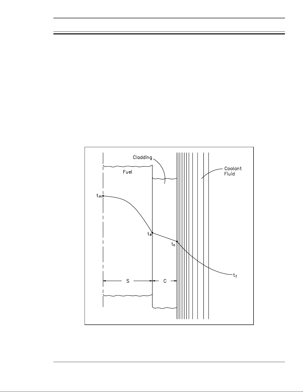
A radial temperature profile across a reactor core (assuming all channel coolant flows are equal)
will basically follow the radial power distribution. The areas with the highest heat generation
rate (power) will produce the most heat and have the highest temperatures. A radial temperature
profile for an individual fuel rod and coolant channel is shown in Figure 17. The basic shape
of the profile will be dependent upon the heat transfer coefficient of the various materials
involved. The temperature differential across each material will have to be sufficient to transfer
the heat produced. Therefore, if we know the heat transfer coefficient for each material and the
heat flux, we can calculate peak fuel temperatures for a given coolant temperature.
Figure 17 Radial Temperature Profile Across a
Fuel Rod and Coolant Channel
Rev. 0 Page 49 HT-02
Simpo PDF Merge and Split Unregistered Version - http://www.simpopdf.com

HEAT GENERATION Heat Transfer
Volumetric Thermal Source Strength
The total heat output of a reactor core is called the heat generation rate. The heat generation
rate divided by the volume of fuel will give the average volumetric thermal source strength. The
volumetric thermal source strength may be used to calculate the heat output of any section of fuel
rod, provided the volume of the section is known.
Volumetric Thermal Source Strength
˙
Qcore
Vfuel
Fuel Changes During Reactor Operation
During the operation of a nuclear reactor, physical changes occur to the fuel that affect its ability
to transfer heat to the coolant. The exact changes that occur are dependant on the type and form
of fuel. Some reactors use fuel assemblies that consist of zircalloy tubes containing cylindrical
ceramic pellets of uranium dioxide. During manufacture, a small space or gap is left between
the fuel pellets and the zircalloy tube (clad). This gap is filled with pressurized helium. As the
reactor is operated at power, several physical changes occur in the fuel that affect the gap
between the pellets and clad. One change occurs due to high pressure in the coolant outside the
clad and the relatively high temperature of the clad during reactor operation. The high
temperature and high pressure causes the clad to be pushed in on the pellets by a process referred
to as creep. Another physical change is caused by the fission process. Each fission event creates
two fission product atoms from a fuel atom. Even though each fission product atom is roughly
half the mass of the fuel atom, the fission products take up more volume than the original fuel
atom. Fission products that are gases can collect together and form small gas bubbles within the
fuel pellet. These factors cause the fuel pellets to swell, expanding them out against the clad.
So the two processes of pellet swell and clad creep both work to reduce the gap between the fuel
and clad.
This change in the gap between the pellet and clad has significant impact on heat transfer from
the fuel and operating fuel temperatures. Initially a significant temperature difference exists
across the gap to cause heat transfer to take place by convection through the helium gas. As the
size of the gap is reduced, a smaller temperature difference can maintain the same heat flux.
When the fuel pellets and clad come in contact, heat transfer by conduction replaces convection
and the temperature difference between the fuel surface and clad decreases even more. Due to
the processes of pellet swell and clad creep, the fuel temperatures of some reactors decrease
slightly over time while the heat flux from the fuel and therefore the power of the reactor remain
constant.
Not all changes that occur to the fuel during reactor operation work to enhance heat transfer.
If the chemistry of the coolant is not carefully controlled within appropriate limits, chemical
reactions can take place on the surface of the clad, resulting in the formation of a layer of
corrosion products or crud between the metal of the clad and the coolant. Typically, this layer
will have a lower thermal conductivity than that of the clad material, so it will act as an
insulating blanket, reducing heat transfer.
HT-02 Page 50 Rev. 0
Simpo PDF Merge and Split Unregistered Version - http://www.simpopdf.com

Heat Transfer HEAT GENERATION
If this corrosion layer is allowed to form, a larger temperature difference will be required
between the coolant and fuel to maintain the same heat flux. Therefore, operation at the same
power level will cause higher fuel temperatures after the buildup of corrosion products and crud.
Summary
The important information in this chapter is summarized below:
Heat Generation Summary
• The power generation process in a nuclear core is directly proportional to the
fission rate of the fuel and the thermal neutron flux present.
• The thermal power produced by a reactor is directly related to the mass flow rate
of the reactor coolant and the temperature difference across the core.
• The nuclear enthalpy rise hot channel factor is the ratio of the total kW heat
generation along a fuel rod with the highest total kW, to the total kW of the
average fuel rod.
• The average linear power density in the core is the total thermal power divided
by the active length of the fuel rods.
• The nuclear heat flux hot channel factor is the ratio of the maximum heat flux
expected at any area to the average heat flux for the core.
• The total heat output of a reactor core is called the heat generation rate.
• The heat generation rate divided by the volume of fuel will give the average
volumetric thermal source strength.
Rev. 0 Page 51 HT-02
Simpo PDF Merge and Split Unregistered Version - http://www.simpopdf.com

DECAY HEAT Heat Transfer
DECAY HEAT
Decay heat production is a particular problem associated with nuclear
reactors. Even though the reactor is shut down, heat is produced from
the decay of fission fragments. Limits for each particular reactor are
established to prevent damage to fuel assemblies due to decay heat.
EO 2.7 DEFINE the term decay heat.
EO 2.8 Given the operating conditions of a reactor core and the
necessary formulas, CALCULATE the core decay heat
generation.
EO 2.9 DESCRIBE two categories of methods for removing
decay heat from a reactor core.
Reactor Decay Heat Production
A problem peculiar to power generation by nuclear reactors is that of decay heat. In fossil fuel
facilities, once the combustion process is halted, there is no further heat generation, and only a
relatively small amount of thermal energy is stored in the high temperature of plant components.
In a nuclear facility, the fission of heavy atoms such as isotopes of uranium and plutonium results
in the formation of highly radioactive fission products. These fission products radioactively
decay at a rate determined by the amount and type of radioactive nuclides present. Some
radioactive atoms will decay while the reactor is operating and the energy released by their decay
will be removed from the core along with the heat produced by the fission process. All
radioactive materials that remain in the reactor at the time it is shut down and the fission process
halted will continue to decay and release energy. This release of energy by the decay of fission
products is called decay heat.
The amount of radioactive materials present in the reactor at the time of shutdown is dependent
on the power levels at which the reactor operated and the amount of time spent at those power
levels. The amount of decay heat is very significant. Typically, the amount of decay heat that
will be present in the reactor immediately following shutdown will be roughly 7% of the power
level that the reactor operated at prior to shutdown. A reactor operating at 1000 MW will
produce 70 MW of decay heat immediately after a shutdown. The amount of decay heat
produced in the reactor will decrease as more and more of the radioactive material decays to
some stable form. Decay heat may decrease to about 2% of the pre-shutdown power level within
the first hour after shutdown and to 1% within the first day. Decay heat will continue to
decrease after the first day, but it will decrease at a much slower rate. Decay heat will be
significant weeks and even months after the reactor is shutdown.
HT-02 Page 52 Rev. 0
Simpo PDF Merge and Split Unregistered Version - http://www.simpopdf.com

Heat Transfer DECAY HEAT
The design of the reactor must allow for the removal of this decay heat from the core by some
means. If adequate heat removal is not available, decay heat will increase the temperatures in
the core to the point that fuel melting and core damage will occur. Fuel that has been removed
from the reactor will also require some method of removing decay heat if the fuel has been
exposed to a significant neutron flux. Each reactor facility will have its own method of removing
decay heat from both the reactor core and also any irradiated fuel removed from the core.
Calculation of Decay Heat
The amount of decay heat being generated in a fuel assembly at any time after shutdown can be
calculated in two ways. The first way is to calculate the amount of fission products present at
the time of shutdown. This is a fairly detailed process and is dependent upon power history.
For a given type of fuel, the concentrations, decay energies, and half lives of fission products are
known. By starting from a known value, based on power history at shutdown, the decay heat
generation rate can be calculated for any time after shutdown.
An exact solution must take into account the fact that there are hundreds of different
radionuclides present in the core, each with its own concentration and decay half-life. It is
possible to make a rough approximation by using a single half-life that represents the overall
decay of the core over a certain period of time. An equation that uses this approximation is
Equation 2-16.
(2-16)
˙
Q˙
Qo
1
2
time
half life
where:
= decay heat generation rate at some time after shutdown
˙
Q
= initial decay heat immediately after shutdown
˙
Qo
time = amount of time since shutdown
half-life = overall decay half-life of the core
Rev. 0 Page 53 HT-02
Simpo PDF Merge and Split Unregistered Version - http://www.simpopdf.com
![Hệ Phun Nhiên Liệu: Chương 3 [Chi Tiết]](https://cdn.tailieu.vn/images/document/thumbnail/2015/20151217/dgvntg/135x160/1019353370.jpg)
![Nhiên liệu xăng: Chương 2 [Thông tin chi tiết]](https://cdn.tailieu.vn/images/document/thumbnail/2015/20151208/cong2000/135x160/2018436326.jpg)

![Mô đun Sản phẩm dầu mỏ (Phần 2): [Mô tả chi tiết hoặc Lợi ích cụ thể]](https://cdn.tailieu.vn/images/document/thumbnail/2015/20151013/uocvong06/135x160/2027873767.jpg)
![Nhiên liệu diesel sinh học Biodiesel: Chuyên đề [Mới nhất]](https://cdn.tailieu.vn/images/document/thumbnail/2013/20130619/beembank123/135x160/891371638131.jpg)


![Cẩm nang Gia công kim loại Việt Nam [mới nhất]](https://cdn.tailieu.vn/images/document/thumbnail/2026/20260513/baobinh_011/135x160/7971778670576.jpg)


![Giáo trình Hàn ống nâng cao (Nghề Hàn - CĐ) Trường Cao đẳng nghề Hải Dương [Mới nhất]](https://cdn.tailieu.vn/images/document/thumbnail/2025/20251212/laphong0906/135x160/47521779076565.jpg)


%20--%3e%3cdefs%3e%3cstyle%3e%20.st0%20{%20fill:%20%23fff;%20}%20.st1%20{%20fill:%20%237800fa;%20}%20%3c/style%3e%3c/defs%3e%3cpath%20class='st1'%20d='M117.78,12.18H43.11c2.9,3.47,4.65,7.94,4.65,12.82,0,5.6-2.3,10.66-6.01,14.29h76.02l7.22-13.56-7.22-13.56Z'/%3e%3cg%3e%3cpath%20class='st0'%20d='M53.58,26.17h-.59v-1.46h.59v-4.96h2.83c1.78,0,2.67.94,2.67,2.82v5.76c0,1.87-.89,2.81-2.67,2.81h-2.83v-4.96ZM55.36,21.37v3.34h1.1v1.46h-1.1v3.34h1.01c.61,0,.91-.37.91-1.1v-5.93c0-.74-.3-1.1-.91-1.1h-1.01Z'/%3e%3cpath%20class='st0'%20d='M65.99,31.14h-1.8l-.31-2.07h-2.19l-.31,2.07h-1.64l1.82-11.39h2.62l1.82,11.39ZM65.28,18.04c-.25.46-.51.77-.75.94-.21.15-.47.22-.79.22-.26,0-.57-.07-.92-.22l-.38-.15c-.14-.05-.26-.07-.37-.07-.3,0-.53.18-.71.54l-.91-.68c.25-.46.51-.77.75-.94.21-.14.48-.21.79-.21.26,0,.57.07.92.21l.38.15c.14.05.26.07.37.07.3,0,.53-.18.71-.54l.91.68ZM61.91,27.52h1.73l-.87-5.76-.87,5.76Z'/%3e%3cpath%20class='st0'%20d='M74.53,26.89v1.52c0,1.91-.89,2.86-2.67,2.86s-2.67-.95-2.67-2.86v-5.93c0-1.91.89-2.86,2.67-2.86s2.67.95,2.67,2.86v1.11h-1.69v-1.22c0-.75-.31-1.12-.93-1.12s-.93.37-.93,1.12v6.15c0,.74.31,1.11.93,1.11s.93-.37.93-1.11v-1.63h1.69Z'/%3e%3cpath%20class='st0'%20d='M81.4,31.14h-1.8l-.31-2.07h-2.19l-.31,2.07h-1.64l1.82-11.39h2.62l1.82,11.39ZM75.9,19.2l1.52-1.91h1.71l1.51,1.91h-1.61l-.76-.95-.75.95h-1.61ZM77.32,27.52h1.73l-.87-5.76-.87,5.76ZM83.1,15.99l-1.76,1.91h-1.26l1.17-1.91h1.86Z'/%3e%3cpath%20class='st0'%20d='M84.86,19.75c1.78,0,2.67.94,2.67,2.82v1.48c0,1.87-.89,2.81-2.67,2.81h-.85v4.28h-1.79v-11.39h2.64ZM84.01,21.37v3.86h.85c.58,0,.87-.36.87-1.08v-1.71c0-.71-.29-1.07-.87-1.07h-.85Z'/%3e%3cpath%20class='st0'%20d='M93.51,19.75c1.78,0,2.67.94,2.67,2.82v1.48c0,1.87-.89,2.81-2.67,2.81h-.85v4.28h-1.79v-11.39h2.64ZM92.66,21.37v3.86h.85c.58,0,.87-.36.87-1.08v-1.71c0-.71-.29-1.07-.87-1.07h-.85Z'/%3e%3cpath%20class='st0'%20d='M98.8,31.14h-1.79v-11.39h1.79v4.88h2.03v-4.88h1.83v11.39h-1.83v-4.88h-2.03v4.88Z'/%3e%3cpath%20class='st0'%20d='M105.36,24.55h2.46v1.62h-2.46v3.34h3.09v1.63h-4.88v-11.39h4.88v1.63h-3.09v3.18ZM108.17,17.29l-1.76,1.91h-1.26l1.17-1.91h1.86Z'/%3e%3cpath%20class='st0'%20d='M112.2,19.75c1.78,0,2.67.94,2.67,2.82v1.48c0,1.87-.89,2.81-2.67,2.81h-.85v4.28h-1.79v-11.39h2.64ZM111.35,21.37v3.86h.85c.58,0,.87-.36.87-1.08v-1.71c0-.71-.29-1.07-.87-1.07h-.85Z'/%3e%3c/g%3e%3ccircle%20class='st1'%20cx='25'%20cy='25'%20r='20'/%3e%3cpath%20class='st0'%20d='M32.78,19.27c2.92,0,4.43,2.55,5.28,5.33l.71,2.17c.14.38-.33.75-.71.75h-5.61c.19-.33.24-.71.09-1.08l-.75-2.45c-.43-1.32-.99-2.64-1.79-3.77.75-.57,1.65-.94,2.78-.94h0ZM25,18.38c3.25,0,4.9,2.78,5.89,5.89l.76,2.45c.14.42-.33.8-.8.8h-11.69c-.42,0-.94-.38-.8-.8l.75-2.45c.99-3.11,2.64-5.89,5.89-5.89h0ZM25,11.35c1.74,0,3.11,1.37,3.11,3.11s-1.37,3.11-3.11,3.11-3.11-1.41-3.11-3.11,1.41-3.11,3.11-3.11h0ZM17.27,19.27c1.08,0,1.98.38,2.73.94-.8,1.13-1.37,2.45-1.74,3.77l-.8,2.45c-.14.38-.05.75.09,1.08h-5.56c-.42,0-.9-.38-.75-.75l.71-2.17c.9-2.78,2.41-5.33,5.33-5.33h0ZM17.27,12.91c1.51,0,2.78,1.27,2.78,2.83s-1.27,2.83-2.78,2.83-2.83-1.27-2.83-2.83,1.27-2.83,2.83-2.83h0ZM32.78,12.91c1.56,0,2.78,1.27,2.78,2.83s-1.23,2.83-2.78,2.83-2.83-1.27-2.83-2.83,1.27-2.83,2.83-2.83h0ZM27.07,28.56v.09c0,.57-.24,1.08-.61,1.46h0v.05c-.38.33-.9.57-1.46.57s-1.08-.24-1.46-.61h0c-.38-.38-.61-.9-.61-1.46v-.09h1.41v.09c0,.19.05.38.19.47v.05c.09.09.28.19.47.19s.38-.09.47-.19v-.05c.14-.09.24-.28.24-.47t-.05-.09h1.41ZM30.99,28.56v.09c0,1.65-.66,3.16-1.74,4.24-1.08,1.08-2.59,1.79-4.24,1.79s-3.16-.71-4.24-1.79l-.05-.05c-1.04-1.08-1.7-2.55-1.7-4.2v-.09h1.41v.09c0,1.27.47,2.4,1.27,3.25h.05c.85.85,1.98,1.37,3.25,1.37s2.4-.52,3.25-1.37c.85-.8,1.37-1.98,1.37-3.25v-.09h1.37ZM34.99,28.56v.09c0,2.78-1.13,5.28-2.92,7.07-1.79,1.79-4.29,2.92-7.07,2.92s-5.23-1.13-7.07-2.92c-1.79-1.79-2.92-4.29-2.92-7.07v-.09h1.41v.09c0,2.4.94,4.53,2.5,6.08,1.56,1.56,3.72,2.5,6.08,2.5s4.52-.94,6.08-2.5c1.56-1.56,2.5-3.68,2.5-6.08v-.09h1.41Z'/%3e%3c/svg%3e)