
Chapter 20
476
Returning to Operation as a Peripheral
When finished communicating, the B-device returns to its role as a peripheral
using the following protocol:
1. The B-device stops all bus activity and may switch in its pull-up resistor.
2. The A-device detects a lack of activity for at least 3 ms and switches out its
pull-up resistor or removes VBUS to end the session.
3. If VBUS is present and the B-device didn’t switch in its pull-up in Step 1, the
B-device switches in its pull-up to connect as a peripheral. The bus is in the J
state.
4. If VBUS is present, the A-device resets the bus. The A-device can then enu-
merate and communicate with the B-device, suspend the bus, or end the session
by removing VBUS.
/#$-"%
If the A-device has turned off the VBUS voltage, a B-device can use the Session
Request Protocol (SRP) to request the host to restore VBUS and begin a new
session. The two SRP methods are data-line pulsing and VBUS pulsing. The
B-device must try data-line pulsing first, followed by VBUS pulsing. An
A-device that supports SRP must respond to one of the methods.
An A-device must respond to SRP if the device ever turns off VBUS while a
micro-A plug is inserted. A B-device must support initiating SRP if the device
wants to request communications with an OTG device when VBUS is off. A
B-device whose targeted peripheral list has no devices that support SRP will
have no need to initiate SRP.
In data-line pulsing, the device switches in its pull-up (on D+ or D-, depending
on device speed) for 5–10 ms. In VBUS pulsing, the device must drive the
VBUS line long enough for the host to detect the VBUS voltage but not long
enough to damage a non-OTG host that isn’t designed to withstand a voltage
applied to VBUS. Because VBUS capacitance is much higher on a non-OTG
host, the voltage rises more slowly. Within 5 seconds of detecting data-line
pulsing or VBUS pulsing, the A-device must turn on VBUS and reset the bus.
Standard hubs don’t recognize SRP signaling, so if there is a hub between the
B-device and the A-device, the B-device can’t use SRP. Non-OTG USB periph-
erals also have the option to support SRP.

Hosts for Embedded Systems
477
#"+$"
When VBUS is present and the bus is suspended, an OTG device can use
remote wakeup to request communications from an OTG device or other USB
host.
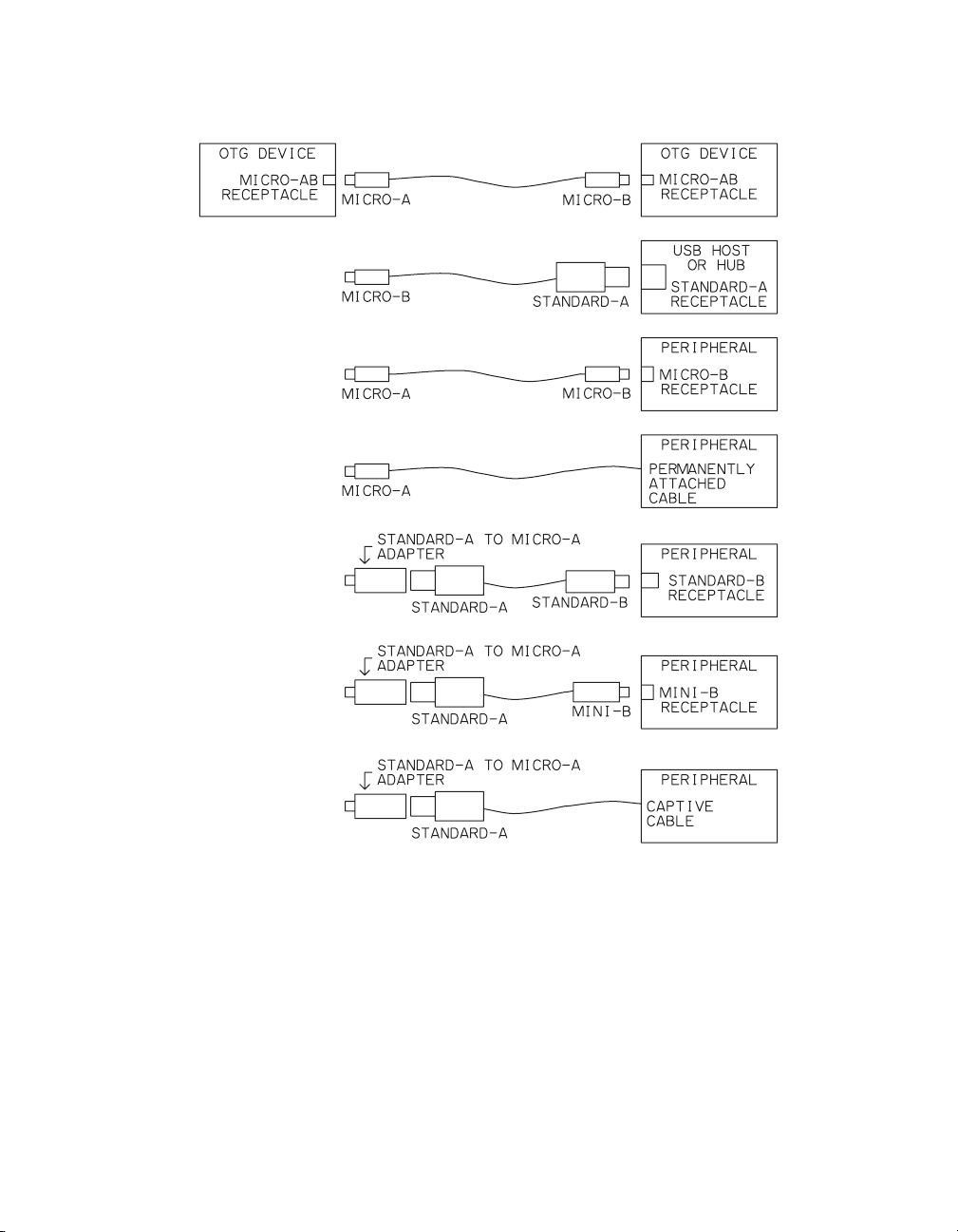
A device with a Micro-AB receptacle is an OTG device. Every OTG device
must have one and only one Micro-AB receptacle, and any device with a
Micro-AB connector must function as a OTG device. The Micro-AB receptacle
can accept either a Micro-A plug or a Micro-B plug.
Figure 20-1 shows the cabling options. Two OTG devices connect to each other
via a cable with a Micro-A plug on one end and a Micro-B plug on the other
end. It doesn’t matter which device has which plug.
A host or upstream hub connects to an OTG device via a Standard-A to
Micro-B cable. A peripheral with a Micro-B receptacle connects to an OTG
device with a Micro-A-to-Micro-B cable. A peripheral with a permanently
attached cable with a Micro-A plug attaches directly to the OTG device.
A peripheral with a Standard-B or Mini-B plug or a captive cable with a Stan-
dard-A plug must use an adapter to connect to an OTG device. The adapter has
a Micro-A plug and a Standard-A receptacle. The Micro-A plug attaches to the
OTG device. The Standard-A receptacle accepts a Standard-A plug from a cable
that attaches to the peripheral with a Standard-B or Mini-B plug or a captive
cable. This adapter is the only approved adapter for standard USB cables.
Micro-A, Micro-B, and Micro-AB connectors have an ID pin that enables an
OTG device to determine whether a Micro-A or Micro-B plug is attached. In a
Micro-A plug, the ID pin is grounded. In a Micro-B plug, the ID pin is open or
connected to ground via a resistance greater than 1MΩ.(The MicroUSB
Micro-B ID Pin Resistance ECN raised this value from its original 100kΩ.) An
OTG device typically has a pull-up resistor on the ID pin. If the pin is a logic
low, the attached plug is a Micro-A. If the pin is a logic high, the attached plug
is a Micro-B.
The USB 3.0 specification defines a USB 3.0 Micro-AB receptacle and USB
3.0 Micro-A plug that include contacts for SuperSpeed traffic.
Chapter 20
478
)""
The ability to draw up to 500 mA per port from the bus is a convenience for
users and a cost saver for device manufacturers. But providing this much cur-
rent, or even the 100 mA that USB 2.0 battery-powered hosts must provide,
can be a burden for some hosts. Some peripherals, including battery-powered
ones, may not need bus power at all.
Figure 20-1. An OTG device can communicate with a USB host or a device on
the OTG device’s target peripheral list.

Hosts for Embedded Systems
479
For these reasons, OTG devices have more flexible requirements for providing
bus current. A USB 2.0 OTG device must provide the greater of 8 mA of bus
current or the maximum amount the devices on the targeted peripheral list
require, up to 500 mA.
To conserve power, an A-device can leave VBUS unpowered until the device
detects SRP signaling or launches an application that uses USB. For faster
response when a device is attached, an A-device can have an option to power
the bus on detecting device attachment.
Every OTG device must have a display or another means to display error mes-
sages to users. To pass compliance tests, an OTG device should support these
messages:
Device not connected/responding. A device isn’t working as expected.
Attached device not supported. A device isn’t on the targeted peripheral list or a
B-device is drawing more current than the A-device supports.
Unsupported hub topology. The device doesn’t support hubs, the bus has more
hub tiers than the A-device supports, or the bus is using another unsupported
hub topology.
A very basic messaging system is a series of LEDs with each labeled with an
error message.
// %,
Every OTG device must have a targeted peripheral list that names the devices
the manufacturer has successfully tested with the OTG device. For each periph-
eral, the list should name the manufacturer and model number and describe the
device. The list should not claim to support an entire class or other devices sim-
ilar to those on the list. The OTG supplement doesn’t say where the list must
appear.
6G;6G
During enumeration, a device that supports HNP or SRP must include an
OTG descriptor (Table 20-2) in the descriptors returned in response to a Get
Descriptor request for the Configuration descriptor. The bmAttributes field
tells whether the device supports HNP and SRP. A device that supports HNP
must support SRP. The A-device doesn’t need to know in advance if a device
Chapter 20
480
supports SRP, but this information is included in the descriptor for use in com-
pliance testing.
G GG")A&
The OTG supplement defines three codes for use in Set Feature requests.
A code of b_hnp_enable (03h) informs the B-Device that it can use HNP. The
A-device sends this request if all of the following are true: the A-device supports
HNP, the A-device will respond to HNP when the bus is suspended, and the
B-device connects directly to the A-device with no hubs in between.
A code of a_hnp_support (04h) informs the B-device that the A-device sup-
ports HNP and the B-device is directly connected (no hubs). The A-device can
send this request before configuring the B-device. The A-device can then enable
HNP at a later time when the A-device is finished using the bus.
A code of a_alt_hnp_support (05h) notifies the B-device that the currently con-
nected port does not support HNP, but that the A-device has an alternate port
that does support HNP.
G)
Some embedded hosts don’t need to function as a device at all, or they need to
support host and device functions at the same time. For these applications, the
USB-IF document Requirements and Recommendations for USB Products with
Embedded Hosts and/or Multiple Receptacles offers guidance.
The document specifies logo requirements and presents additional recommen-
dations for products that contain embedded host ports. Like OTG hosts, these
hosts have limited resources and generally don’t run general-purpose,
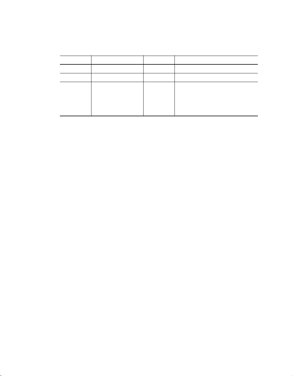
Table 20-2: The OTG Descriptor indicates whether a device supports
HNP and SRP.
4 3 *
0 bLength 1 Descriptor length (3)
1bDescriptorType1OTG (9)
2 bmAttributes 1 D2–D7: reserved,
D1: 1 = HNP supported,
0 = HNP not supported
D0: 1 = SNP supported,
0 = SNP not supported


![Ngân hàng đề thi trắc nghiệm Kiến trúc máy tính [mới nhất]](https://cdn.tailieu.vn/images/document/thumbnail/2026/20260514/hoahongxanh0906/135x160/49281779160279.jpg)


%20--%3e%3cdefs%3e%3cstyle%3e%20.st0%20{%20fill:%20%23fff;%20}%20.st1%20{%20fill:%20%237800fa;%20}%20%3c/style%3e%3c/defs%3e%3cpath%20class='st1'%20d='M117.78,12.18H43.11c2.9,3.47,4.65,7.94,4.65,12.82,0,5.6-2.3,10.66-6.01,14.29h76.02l7.22-13.56-7.22-13.56Z'/%3e%3cg%3e%3cpath%20class='st0'%20d='M53.58,26.17h-.59v-1.46h.59v-4.96h2.83c1.78,0,2.67.94,2.67,2.82v5.76c0,1.87-.89,2.81-2.67,2.81h-2.83v-4.96ZM55.36,21.37v3.34h1.1v1.46h-1.1v3.34h1.01c.61,0,.91-.37.91-1.1v-5.93c0-.74-.3-1.1-.91-1.1h-1.01Z'/%3e%3cpath%20class='st0'%20d='M65.99,31.14h-1.8l-.31-2.07h-2.19l-.31,2.07h-1.64l1.82-11.39h2.62l1.82,11.39ZM65.28,18.04c-.25.46-.51.77-.75.94-.21.15-.47.22-.79.22-.26,0-.57-.07-.92-.22l-.38-.15c-.14-.05-.26-.07-.37-.07-.3,0-.53.18-.71.54l-.91-.68c.25-.46.51-.77.75-.94.21-.14.48-.21.79-.21.26,0,.57.07.92.21l.38.15c.14.05.26.07.37.07.3,0,.53-.18.71-.54l.91.68ZM61.91,27.52h1.73l-.87-5.76-.87,5.76Z'/%3e%3cpath%20class='st0'%20d='M74.53,26.89v1.52c0,1.91-.89,2.86-2.67,2.86s-2.67-.95-2.67-2.86v-5.93c0-1.91.89-2.86,2.67-2.86s2.67.95,2.67,2.86v1.11h-1.69v-1.22c0-.75-.31-1.12-.93-1.12s-.93.37-.93,1.12v6.15c0,.74.31,1.11.93,1.11s.93-.37.93-1.11v-1.63h1.69Z'/%3e%3cpath%20class='st0'%20d='M81.4,31.14h-1.8l-.31-2.07h-2.19l-.31,2.07h-1.64l1.82-11.39h2.62l1.82,11.39ZM75.9,19.2l1.52-1.91h1.71l1.51,1.91h-1.61l-.76-.95-.75.95h-1.61ZM77.32,27.52h1.73l-.87-5.76-.87,5.76ZM83.1,15.99l-1.76,1.91h-1.26l1.17-1.91h1.86Z'/%3e%3cpath%20class='st0'%20d='M84.86,19.75c1.78,0,2.67.94,2.67,2.82v1.48c0,1.87-.89,2.81-2.67,2.81h-.85v4.28h-1.79v-11.39h2.64ZM84.01,21.37v3.86h.85c.58,0,.87-.36.87-1.08v-1.71c0-.71-.29-1.07-.87-1.07h-.85Z'/%3e%3cpath%20class='st0'%20d='M93.51,19.75c1.78,0,2.67.94,2.67,2.82v1.48c0,1.87-.89,2.81-2.67,2.81h-.85v4.28h-1.79v-11.39h2.64ZM92.66,21.37v3.86h.85c.58,0,.87-.36.87-1.08v-1.71c0-.71-.29-1.07-.87-1.07h-.85Z'/%3e%3cpath%20class='st0'%20d='M98.8,31.14h-1.79v-11.39h1.79v4.88h2.03v-4.88h1.83v11.39h-1.83v-4.88h-2.03v4.88Z'/%3e%3cpath%20class='st0'%20d='M105.36,24.55h2.46v1.62h-2.46v3.34h3.09v1.63h-4.88v-11.39h4.88v1.63h-3.09v3.18ZM108.17,17.29l-1.76,1.91h-1.26l1.17-1.91h1.86Z'/%3e%3cpath%20class='st0'%20d='M112.2,19.75c1.78,0,2.67.94,2.67,2.82v1.48c0,1.87-.89,2.81-2.67,2.81h-.85v4.28h-1.79v-11.39h2.64ZM111.35,21.37v3.86h.85c.58,0,.87-.36.87-1.08v-1.71c0-.71-.29-1.07-.87-1.07h-.85Z'/%3e%3c/g%3e%3ccircle%20class='st1'%20cx='25'%20cy='25'%20r='20'/%3e%3cpath%20class='st0'%20d='M32.78,19.27c2.92,0,4.43,2.55,5.28,5.33l.71,2.17c.14.38-.33.75-.71.75h-5.61c.19-.33.24-.71.09-1.08l-.75-2.45c-.43-1.32-.99-2.64-1.79-3.77.75-.57,1.65-.94,2.78-.94h0ZM25,18.38c3.25,0,4.9,2.78,5.89,5.89l.76,2.45c.14.42-.33.8-.8.8h-11.69c-.42,0-.94-.38-.8-.8l.75-2.45c.99-3.11,2.64-5.89,5.89-5.89h0ZM25,11.35c1.74,0,3.11,1.37,3.11,3.11s-1.37,3.11-3.11,3.11-3.11-1.41-3.11-3.11,1.41-3.11,3.11-3.11h0ZM17.27,19.27c1.08,0,1.98.38,2.73.94-.8,1.13-1.37,2.45-1.74,3.77l-.8,2.45c-.14.38-.05.75.09,1.08h-5.56c-.42,0-.9-.38-.75-.75l.71-2.17c.9-2.78,2.41-5.33,5.33-5.33h0ZM17.27,12.91c1.51,0,2.78,1.27,2.78,2.83s-1.27,2.83-2.78,2.83-2.83-1.27-2.83-2.83,1.27-2.83,2.83-2.83h0ZM32.78,12.91c1.56,0,2.78,1.27,2.78,2.83s-1.23,2.83-2.78,2.83-2.83-1.27-2.83-2.83,1.27-2.83,2.83-2.83h0ZM27.07,28.56v.09c0,.57-.24,1.08-.61,1.46h0v.05c-.38.33-.9.57-1.46.57s-1.08-.24-1.46-.61h0c-.38-.38-.61-.9-.61-1.46v-.09h1.41v.09c0,.19.05.38.19.47v.05c.09.09.28.19.47.19s.38-.09.47-.19v-.05c.14-.09.24-.28.24-.47t-.05-.09h1.41ZM30.99,28.56v.09c0,1.65-.66,3.16-1.74,4.24-1.08,1.08-2.59,1.79-4.24,1.79s-3.16-.71-4.24-1.79l-.05-.05c-1.04-1.08-1.7-2.55-1.7-4.2v-.09h1.41v.09c0,1.27.47,2.4,1.27,3.25h.05c.85.85,1.98,1.37,3.25,1.37s2.4-.52,3.25-1.37c.85-.8,1.37-1.98,1.37-3.25v-.09h1.37ZM34.99,28.56v.09c0,2.78-1.13,5.28-2.92,7.07-1.79,1.79-4.29,2.92-7.07,2.92s-5.23-1.13-7.07-2.92c-1.79-1.79-2.92-4.29-2.92-7.07v-.09h1.41v.09c0,2.4.94,4.53,2.5,6.08,1.56,1.56,3.72,2.5,6.08,2.5s4.52-.94,6.08-2.5c1.56-1.56,2.5-3.68,2.5-6.08v-.09h1.41Z'/%3e%3c/svg%3e)